A look at how digital techniques have changed and improved analog radios.
Design and construction of a basic analog radio has changed drastically over the years. Radio architecture has evolved from multi-tube designs, to transistors, to integrated circuits, and now, today, to a single chip.
While the rest of the electronics world has gone digital, broadcast radio is still mostly analog. AM, FM, and shortwave (SW) broadcasts are analog, and there are few amongst us that do not listen to one or more of them. That is why there are still hundreds of millions of analog radios still made each year for automobiles, bedside clock radios, portables, high-end stereo systems, and others.
With its enormous population, China is now the largest market for analog radios, but there are still millions sold here in the US.
Radio Basics
Any radio needs two main things: sensitivity and selectivity. Sensitivity means the radio’s ability to receive very small signals and extract the voice, music, or data. Receivers are sensitive because of the gain they provide. Usually, multiple amplifiers are used to allow microvolt level signals to produce full output. The signals are usually amplified before demodulation and after demodulation.
As for selectivity, a radio must be able to be tuned to the desired station, and it must be able to distinguish one signal from another. A radio’s tuner is just a variable filter that will let the desired signal through, and reject others nearby in frequency. In crowded urban areas with many stations, this is especially critical when most broadcast stations are running many kilowatts of power and can easily encroach on one another. Older inductor-capacitor (LC) filters did a fair job, but more recent crystal or ceramic resonator filters are superior. Today, modern digital signal processing (DSP) filters do an even better job.
Radio Circuits
Most radios evolved from a basic design referred to as a superheterodyne. This type of radio converts the incoming signal down in frequency, usually to a lower frequency called the intermediate frequency (or IF). This is done to simplify tuning and provide good fixed frequency selectivity; refer to Figure 1. The basic design includes an RF amplifier after the antenna to amplify the small signal received. Some cheap receivers omitted this stage. The signal then goes to the mixer stage that does the down conversion to IF. It does this by heterodyning the incoming signal with a higher frequency local oscillator (LO) signal.
Heterodyning
Heterodyning is a radio signal processing technique invented in 1901 by Canadian inventor-engineer Reginald Fessenden, in which new frequencies are created by combining or mixing two frequencies. Heterodyning is useful for frequency shifting signals into a new frequency range, and is also involved in the processes of modulation and demodulation. The two frequencies are combined in a nonlinear signal-processing device such as a vacuum tube, transistor, or diode, usually called a mixer. In the most common application, two signals at frequencies f1 and f2 are mixed, creating two new signals, one at the sum f1 + f2 of the two frequencies, and the other at the difference f1 − f2. These new frequencies are called heterodynes. Typically only one of the new frequencies is desired, and the other signal is filtered out of the output of the mixer. Heterodynes are closely related to the phenomenon of "beats" in music.
Courtesy Wikipedia
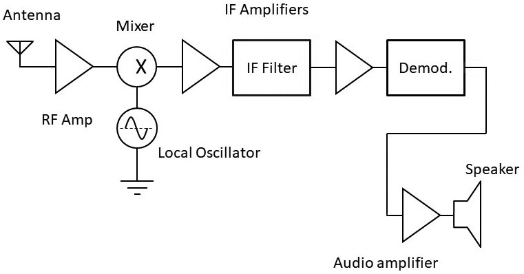
FIGURE 1. Block diagram of a basic superheterodyne radio showing the mixer that down-converts the signal to a low intermediate frequency before demodulation.
The mixer produces the sum and difference signals. The difference signal is usually selected as the IF.
For example, assume the signal is on 98.7 MHz. The mixer combines this with a 109.4 MHz LO signal to generate the sum of 208.1 MHz and the difference of 10.7 MHz. The sum signal is filtered out and the difference is the IF. The 10.7 MHz signal still has all the original modulation on it. That IF signal is then amplified, and selective filters make sure that signals outside the band are rejected.
After some IF amplification and filtering, the signal goes to a detector or demodulator where the modulation is removed. Therefore, the originally transmitted voice or music is recovered. It is then amplified in an audio amplifier and applied to a speaker or some headphones.
Superhet radios were typically built using five or six tubes or transistors plus loads of discrete resistors, capacitors, and diodes. Integrated circuits came along and reduced the component count somewhat to three or four ICs, but many discretes were still used. The large number of discrete components usually results from the complexity of implementing a multiband (AM/FM/SW) receiver that is also tunable over a wide frequency range. There was no way to simplify this beyond a certain point. The form of construction has kept even the basics of radios complex to manufacture.
The Digital Radio
Many units today are what we call software-defined radios (SDR). These radios use a mix of analog and digital techniques to allow almost full integration of most radio functions — including tuning — inside a few ICs. The SDR still uses an RF amplifier to boost the signal level and a mixer to down-convert the signal to a lower IF. Then, however, an analog-to-digital converter (ADC) digitizes the signal into binary words that are then sent to a block of digital signal processing (DSP) circuitry that performs the filtering for selectivity and the demodulation. The recovered signal in digital form is then sent to a digital-to-analog converter (DAC) where the original analog voice or music is recovered. The analog DAC output is then amplified as usual before going to the speaker.
As for tuning, this is usually accomplished with a frequency synthesizer. This is a mixed-signal (analog and digital) circuit called a phase-locked loop (PLL) that generates the LO signal for the mixers in frequency step increments, rather than a continuously variable frequency.
The SDR architecture greatly reduces the number of components needed to implement the radio. In addition, it also significantly improves the receiver selectivity over any analog design.
A Single Chip Radio
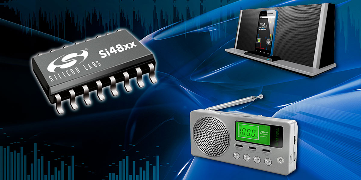
There are multiple vendors making what we call single chip radios. A good example are the radios from Silicon Laboratories. They have been making AM/FM and TV tuners using a mixed-signal approach for several years. One of the more recent is the Si48xx series that puts an entire AM/FM and SW radio in one chip; check out Figure 2. It is designed for making auto radios, tabletops, portables, and other form factors. It uses an SDR approach. There are three versions: Si4825/27/36; each has a slightly different tuning option. The Si4836 has stereo outputs while the other two are monaural output.
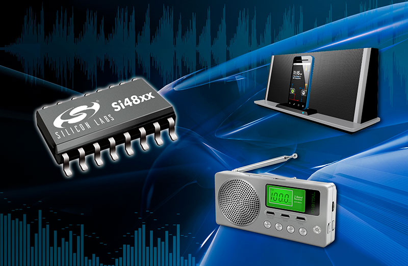
FIGURE 2. Silicon Labs Si48xx series single chip radios cover worldwide AM, FM, and shortwave bands to make any type of consumer radio product.
The block diagram of this single chip radio is shown in Figure 3.
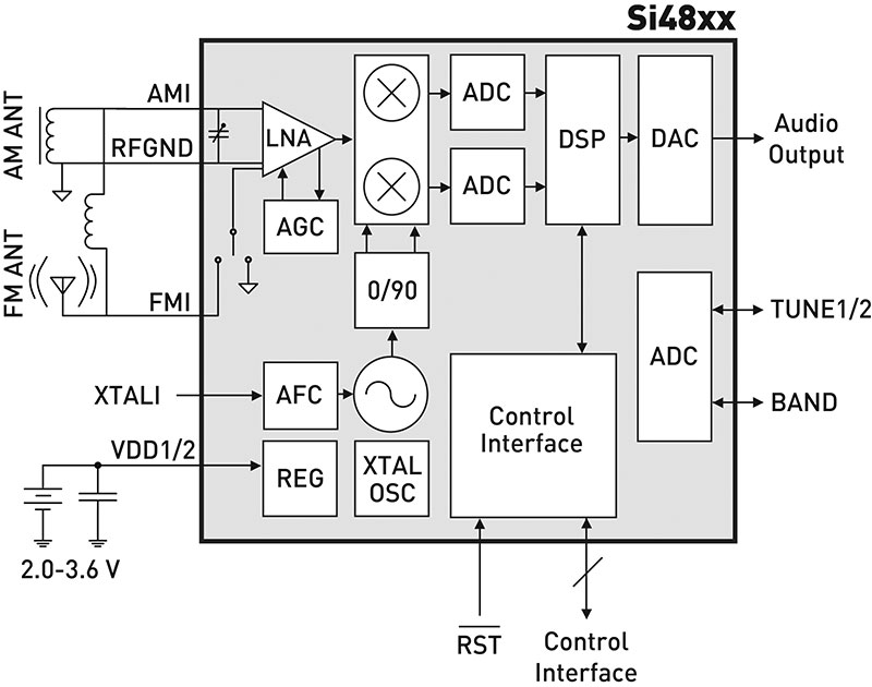
FIGURE 3. Block diagram of the Si4825 single chip radio.
The antenna connects to the input with some inductors for impedance matching to the input amplifier. The input RF amplifier is referred to as a low noise amplifier (LNA) because it amplifies without adding any significant amount of noise to the signal. The amplified signal is sent to two mixers. The local oscillator is a synthesizer that generates two LO sine waves; one shifted 90 degrees from the other. The mixers get the phase shifted signals at the same frequency and then produce two low frequency IF signals shifted 90 degrees from one another. These are called the I and Q signals, meaning in-phase and quadrature (90 degree) phase. The IF is low, in the 100 kHz range. The analog signals are then digitized by the ADCs producing two quadrature bit streams to the DSP. The DSP circuits implement mathematical algorithms to do the IF filtering and demodulation. The DSP output then is a digital form of the original analog modulation that is then sent to the DAC for conversion back to analog for amplification. Another IC power amplifier drives the speaker.
Some of the other circuits are an automatic gain control (AGC) that helps keep the signal level to the mixers as constant as possible, despite signal strength variations. There is also an automatic frequency control (AFC) circuit that keeps the local oscillator on frequency in spite of temperature or other undesired variations. An internal crystal oscillator is used as a reference for the frequency synthesized LO.
The block called control circuitry is used to implement the external frequency display and the tuning. The tuning is handled by an external potentiometer or step attenuator connected to a DC voltage. The varying DC voltage is applied to the TUNE1/2 pin, and converted into a digital number by the ADC and used to set the LO synthesizer on frequency. The whole chip is housed in a 16-pin small outline IC. Power comes from a DC source of 2.0 to 3.6 volts. This is regulated to a constant value by the on-chip regulator.
As for antennas, a standard ferrite core inductor is used for the AM antenna, and the FM antenna is a small collapsible whip. The SW section uses the FM antenna.
The chip radio tunes the full worldwide AM and FM bands. AM range is 504 to 1750 kHz; FM covers 64 to 109 MHz; and SW covers 2.3 to 28.5 MHz.
Tuning and Display Options
Modern radios come in three basic formats: analog-tuned, analog display (ATAD); analog-tuned, digital display (ATDD); and digital-tuned digital display (DTDD). The ATAD radios are the old familiar type using a knob or wheel for tuning, and a circular or linear dial to display the frequency. The ATDD mode uses a knob or wheel for tuning and a digital (LCD or LED) numerical frequency display.
The DTDD radios usually use pushbuttons for channel selection tuning and an LCD or LED display. Humans still seem to prefer a knob for tuning, so the wheel tuned ATDD form is still the most popular. Figure 4 shows an example of this form, although it does not use the Silicon Lab chips.
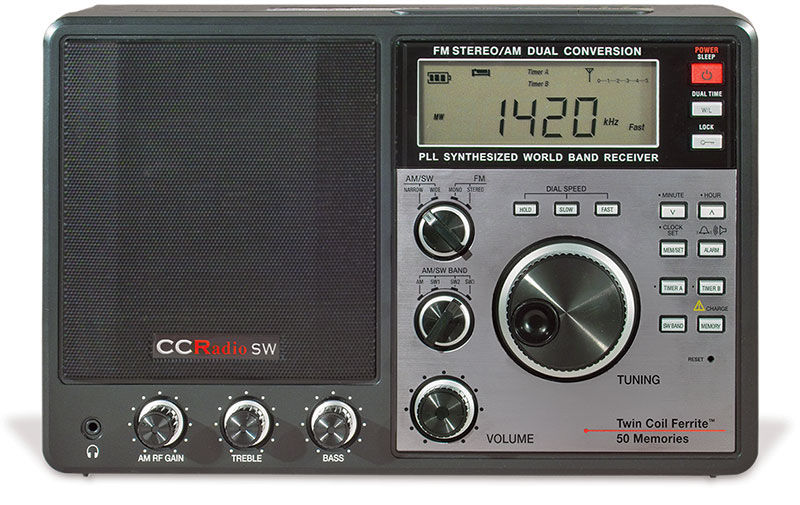
FIGURE 4. A popular analog-tuned, digital display (ATDD) portable AM/FM/SW radio from C Crane Company.
The tuning circuitry inside the Si48xx chips implement the ATDD mode. The radio works with an external embedded microcontroller for the display. An external pot with knob or a detent-type click wheel is used to set the frequency.
For more details on the Silicon Labs chips, see www.silabs.com. NV