Materials that can conduct current (silver, gold, aluminum, copper, etc.) contain large numbers of loosely held electrons. Their resistance to the flow of current is measured in just a few millionths of an ohm per centimeter. Insulators — such as glass, rubber, and plastic — have very few loosely held electrons and their resistance to the flow of current is measured in a few million ohms per centimeter.
Semiconductors
As the term implies, semiconductors are not as conductive as metal, nor are they as non-conductive as insulators. The most commonly used materials in semiconductors are germanium and silicon. Germanium, in its pure form, is rated at 60 ohms per centimeter, while silicon is rated at 60,000 ohms per centimeter.
What enables semiconductors to change their state of conductivity is the addition of controlled amounts of impurities. Arsenic and antimony added to the mix will produce what is known as an n-type material because of the negative charge from the excess of free electrons. A p-type junction can be produced with the careful addition of aluminum, gallium, or indium.
P-N Junction
When a P-type junction is made, the electrical equivalent of “holes” or an absence of electrons is set up. An N junction has an excess of electrons. Combining P and N materials and applying negative current results in a diffusing of electrons across the junction is known as diffusion current.
As you can see in Figure 1, a surplus of electrons from the N material penetrate the space-charge region, flow across the junction, and move through the holes to the positive lead.
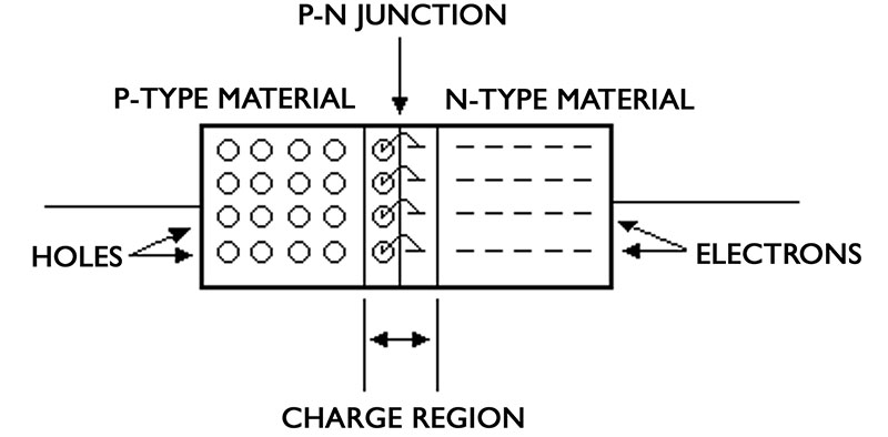
Figure 1. Combined P and N junctions
This is known as forward biasing and results in signal being transferred through the diode.
When the current is reversed, the free electrons are drawn to the positive terminal and the holes are attracted to the negative terminal. This is known as reverse biasing and results in no passage of current through the diode. The more reverse biasing is applied to it, the more resistance the diode presents.
Biasing
Like bipolar transistors, diodes do not respond to signals until a threshold voltage is achieved. The biasing level can vary from one diode to another, but most diodes will trigger at about 0.7 volts. Reverse biasing does not have a threshold and a diode starts responding at the first sign of a signal.
Since diodes are mostly given the duty of switching non-sinusoidal signals, biasing — for the most part — is not a factor.
Doping
Doping is the name given to the process of adding impurities that enable the diode to respond to current. Different doping procedures can produce different types of diodes.
For example, over-doping can produce something called a tunnel diode.
Tunnel Diodes
A tunnel diode has a high concentration of impurities in both the p and the n sections of the device. The space-charge region is so narrow in this diode that an electrical charge can pass through the device by tunneling, a quantum-mechanical action that produces a negative-resistance region that has the potential of achieving amplification.
In circuits where signal intensity is compromised for one reason or another, the tunnel diode can help achieve a critical threshold point. Oscillators, pulse generators, and rf energy generation are the areas where the tunnel diode is most applicable.
Zener Diode
Voltage regulation is an important function in modern electronics and the zener diode is designed to do just that. It achieves this in the reverse bias mode. You can see in the diagram (Figure 2) that the zener is wired across a power supply output with the anode lead connected to ground and the cathode lead connected to the supply output.
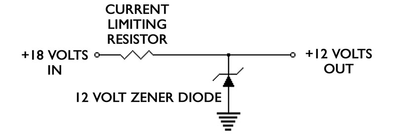
Figure 2. Zener diode operation
Like regular diodes, zener devices resist the flow of voltage when reverse biased. The zener, however, is designed to resist the flow of voltage only to a given breakdown point. Anything over the breakdown point will be passed to ground. Acting as a reference source, the zener diode is capable of providing very accurate, constant current loads.
Popular cutoff points are 5, 9, and 12 volts to accommodate most power supply requirements.
Varactor
One of the most unusual devices is the varactor or variable-reactance diode. The varactor acts as a voltage sensitive capacitor in series with a resistance. Its use is basically
confined to microwave equipment.
Diode Types
As you can see in the illustration, diodes come in a wide variety of shapes and sizes. The size of a diode will most likely relate to its power handling capacity. Leads are identified as anode and cathode and — on most diodes — polarity is identified by a line on the cathode side, as shown in the diode type illustration (Figure 3).
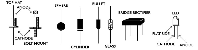
Figure 3. Diode types
Your local supplier should have most types in stock. Low level glass diodes, such as the 1N914, are inexpensive and widely available.
SCRs
An SCR (Silicone Controlled Rectifier) is like a diode with an extra lead. The device will not pass current until a pulse is applied to the third lead, which is called a gate. Many switching functions that were formerly controlled by heavy, slow, expensive mechanical relays can be executed by an SCR.
Loading problems are another disadvantage of relays that disqualifies them from low current circuits, especially since they need a constant DC input to stay on. Only a brief pulse is necessary to turn on an SCR — and it stays on.
There are two ways to turn it off. The first is by applying a negative pulse to the gate and the second is by disengaging the output load. This second method is popular as a reset in alarm circuits (see Figure 4).
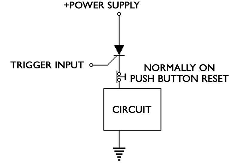
Figure 4. SCR operation
One thing that is necessary when working with SCRs is a constant output load. Most well designed circuits will provide a steady load to maintain the on condition of the SCR.
Experimentation will determine whether or not the circuit will sustain an on condition in an SCR controlled situation.
LEDs
Light Emitting Diodes (LEDs) have been around for quite a while now and almost all electronic devices have one or more. The LED is made by adding metals — such as aluminum, gallium, and indium — to arsenic antimony and phosphors. By changing the ratio of elements, it's possible to vary the color, the amount of infrared radiation, and the brightness greatly from one LED to another.
Wherever you need a visual indication of electrical activity, the LED is the answer. Seven-segment displays enable light emitting diodes to indicate letters and numbers and are used in clocks and calculators. Arrays — consisting of several LEDs in a single case — are used to indicate sound levels in recording devices.
New products are being developed all the time and amazing devices are finding their ways to the shelves of your suppliers.
Diodes as Isolators
No circuit demonstrates the ability of diodes to pass and isolate analog signals better than a sequencer. The sequencer in Figure 5 is a 4017 decade counter and it produces a high output (equal to the power supply) at only one of its 10 outputs.
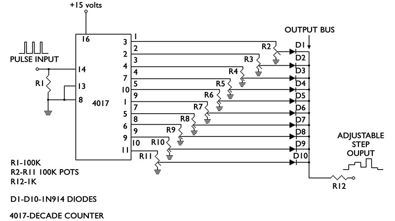
Figure 5. Diode isolated voltage sequencer
The other nine outputs are low and all of the outputs are connected to potentiometers.
When a pulse is fed to pin 14, the counter advances to the next stage. Since only one diode at a time is high, it passes whatever voltage is set by its potentiometer to the output bus. This voltage reverse biases all other diodes, so they become highly resistive and isolate the nine low state outputs.
No interaction between stages will occur because only the voltage at the active stage will be passed to the bus. The result is a manually adjustable staircase wave shape. This circuit is ideally suited to operate voltage controlled oscillators and other electronic music circuits.
Integrated Circuits
Diode elements are etched into ICs to direct signals, prevent false triggering, and stabilize — as well as protect — the circuit. Tunnel diode doping techniques are being researched to increase the efficiency of the new breed of integrated
circuits.
Bar Graph Sound Level Indicator
Figure 6 shows how to use diodes in series to set a “trip point.”
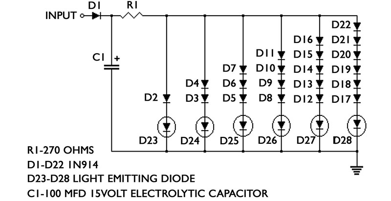
Figure 6. Bar graph sound level indicator
Twenty-two diodes and six LEDs — along with three resistors and a capacitor — comprise this simple sound level indicator. The input accepts a high level audio signal through D1. As a low level signal rises in amplitude, it meets the biasing threshold of diode D2 and LED D23 lights.
When the signal increases beyond the biasing requirement of D3 and D4, LED D24 will light. This process continues down the line to LED D28, as long as the signal level increases.
The new extra bright LEDs work best in this circuit, but, if they are too bright, increase the value of resistor R1.
Because audio levels from music can be transient, signals may occur too quickly to be observed.
Capacitor C1 will help hold the signal long enough for it to be seen. If the capacitor does not hold the signal long enough, try a larger value.
Conclusion
Diodes can help you achieve your circuit goals, whether you want to trigger an alarm, regulate a power supply, or light up a project with LEDs. The diode will point you in the right direction. NV
Additional Helpful Figures
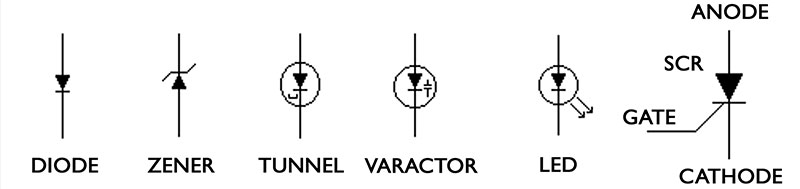
Diode symbols.
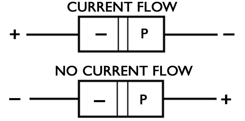
Current flow.
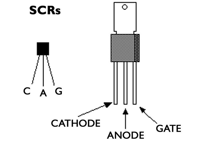
SCRs.
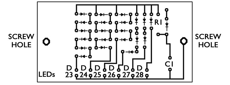
Foil pattern for bargraph circuit.
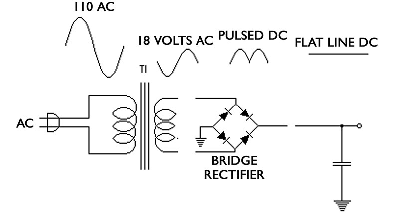
Power supply.