In the case of a communication system, errors happen while information is being transmitted, while it is being delivered to its destination, or while it is being received. However the errors occur, is there anything we can do to protect our information? The answer is yes. In fact, there are many things we can do, with each hardware or software technique falling into one of two categories: error detection or error correction. Error detection is easier to do than error correction, as we will see.
The first hardware technique involves the use of a parity bit. This bit is stored with a group of data bits and is used to indicate the even or odd parity of the data. Even parity means the number of 1s in the data (including the parity bit) is even. Odd parity means the opposite. Table 1 shows a few sample data items and their associated even and odd parity bits.
| 8-Bit Data |
Even Parity Bit |
Odd Parity Bit |
| 10101100 |
0 |
1 |
| 01000110 |
1 |
0 |
| 11110010 |
1 |
0 |
| 10010110 |
0 |
1 |
Table 1: Even and odd parity examples.
The even and odd parity bits are always complements of each other. Figure 1 shows how a single parity bit can be generated using exclusive-OR (XOR) gates.
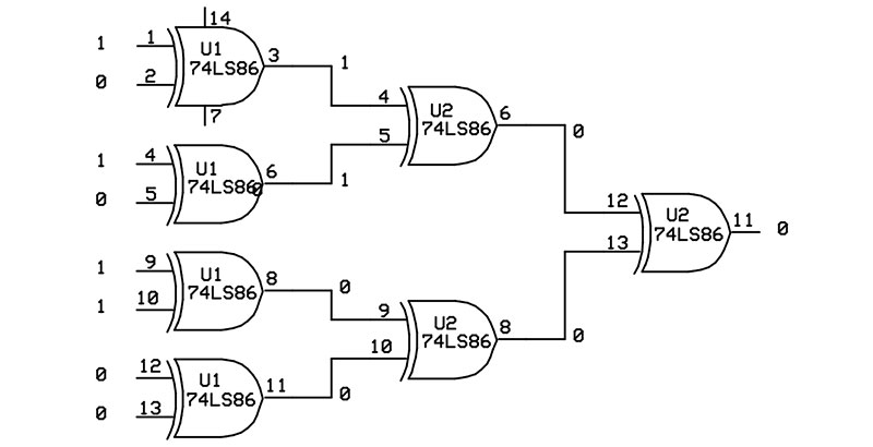
Figure 1. Generating an even parity bit.
The XOR gate outputs a 0 when its inputs are the same (both low or both high) and a 1 when its inputs are different. The input data 10101100 is broken into four groups of two bits, with each pair driving an XOR gate. The eight input bits are reduced to four intermediate bits, then two intermediate bits, then to a single output bit that represents the even parity for the data. Using an exclusive-OR gate as the last gate will generate an odd parity bit.
So, with only a handful of gates, we are able to generate odd or even parity bits. Now, after the parity bit is generated, it is stored with the data or transmitted with it to a receiver. When the data is read back or received, its parity is checked. If the parity does not match, you have detected an error.
Unfortunately, a single parity bit has limitations. It can only detect odd-numbered bit errors. If one bit — or three, five, or seven bits — change, the parity will also change and the error will be detected, but, if an even number of bits change, the parity will remain the same and the error will go undetected.
The limitations of a single parity bit can be overcome by using multiple parity bits. In fact, by using just four parity bits, we are able to detect and correct single bit errors in our eight bits of data. Figure 2(A) shows how four parity bits (three odd and one even) are generated using different groups of bits from the input data. These four bits are called check bits and are transmitted or stored with the original eight data bits.
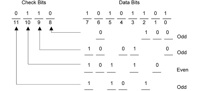
Figure 2. Using multiple parity bits to detect and correct a single bit error. (A) Generating the check bits.
In Figure 2(B), the 12 received bits are again used to generate four parity bits, with these bits representing the error code. An error code of 0000 indicates that no errors have occurred. Any other error code will indicate the specific bit or even groups of bits in error. This technique was developed by Richard Hamming in the 1950s.
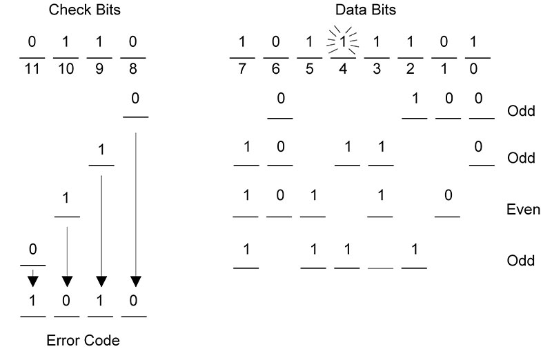
Figure 2. (B) Determining the four-bit error code.
Table 2 shows the four-bit error codes for the Hamming code used in Figure 2.
| Error Code |
Error Bit(s) |
| 0000 |
No error |
| 0001 |
Check bit 0 (bit 8) |
| 0010 |
Check bit 1 (bit 9) |
| 0011 |
Data bit 0 |
| 0100 |
Check bit 2 (bit 10)* |
| 0101 |
Data bit 1 |
| 0110 |
Data bit 3 |
| 0111 |
Data bit 6 |
| 1000 |
Check bit 3 (bit 11) |
| 1001 |
Data bit 2 |
| 1010 |
Data bit 4 |
| 1011 |
All received bits are 0 |
| 1100 |
Data bit 5 |
| 1101 |
Multiple errors |
| 1110 |
Data bit 7 |
| 1111 |
Multiple errors |
*All received bits are 1.
Table 2: Hamming code error patterns.
A deliberate error was introduced into data bit 4. The resulting error code of 1010 correctly identified this single bit error. Once a single bit error has been identified, it is easy to fix it: simply invert the bit that is incorrect.
The ability to detect and correct a single-bit error is important and useful. The price that we pay for this ability is the cost of the four check bits attached to each eight-bit data item. Thus, we have a 50% memory overhead (or bandwidth overhead, during transmission) that must be an acceptable trade-off in order to get the benefit of single bit error correction.
A third hardware technique that can be used with a serial stream of data uses multiple bits to create a check sequence. This technique is called a Cyclic Redundancy Check (CRC) and can be used with bit streams of varying lengths.
The basic method is to treat the serial data stream as a large, binary number. By dividing this number by a predefined binary polynomial, we end up with a remainder pattern (the check sequence) that gets tacked onto the end of the original data.
The check sequence essentially turns the serial stream into a number that is evenly divisible by the polynomial. So, on the receiving end, when the received data (which includes the check sequence) is passed through the CRC circuit, the resulting check sequence will be all 0s if there are no errors. Any 1s that show up indicate one or more errors in the bit stream, but we will not know where they are.
Suppose the data to transmit is 10101100 and the four-bit polynomial is 1011. Generating the check sequence is accomplished through the use of Modulo-2 arithmetic (once again using exclusive-OR). This process is illustrated in Figure 3. A three-bit pattern of 000 is tacked onto the end of the original data. This is done to reserve room for the actual three bits of the check sequence once they are determined.
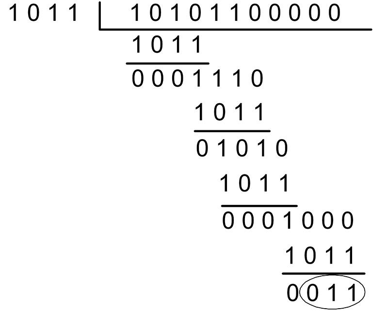
Figure 3. Generating a CRC check sequence.
At each step, four bits of data are XORed with the four-bit polynomial 1011. This process repeats until there are no more bits left in the data. The final three bits remaining are the CRC check sequence (011). This sequence is now tacked onto the end of the original data (giving us 10101100011) and transmitted.
On the receiving end, the same process is used again, with the 011 sequence replacing the original three 0s. If there are no errors, the remainder will be 0. Change one of the bits yourself and verify that the remainder is non-zero.
The CRC generator is easily constructed using a few XOR gates and a shift register. Figure 4 shows the schematic of the CRC generator for the 1011 polynomial.
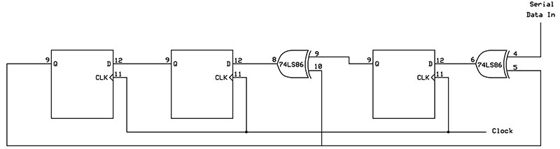
Figure 4. The three-bit shift register used to create a CRC check sequence.
A four-bit divider polynomial requires a three-bit shift register to hold the three remainder bits that make up the check sequence. After all bits have been clocked into the circuit, the shift register will contain the three remainder bits (LSB on the right and MSB on the left).
An eight-bit polynomial would require a seven-bit shift register (and seven 0s tacked onto the original data to begin the process). In general, the shift register has one less stage than the number of bits in the polynomial. Table 3 shows some typical CRC polynomials and their uses.
| Name |
Polynomial |
Application |
| CRC-16 |
X16 + X15 + X 2 + 1 |
Used with ATM |
| CRC-CCITT |
X16 + X12 + X 5 + 1 |
Used with HDLC |
| CRC-32 |
X32 + X26 + X23 + X22 + X16 + X12 + X11 + X10 + X8 + X7 + X5 + X4 + X2 + X + 1 |
Used with Ethernet |
Table 3: Common CRC generator polynomials.
Software techniques for performing error detection and correction are especially useful in the world of networking and the Internet. When we download a web page or send an Email, we want to know that these operations are successful. This guarantees that images and other web page content — as well as Email text and binary attachments — are received without error. Perhaps a better expression would be transferred without error.
If we receive some information and it has been corrupted, we simply ask for it to be retransmitted. This is the beauty of the TCP (Transmission Control Protocol) transport protocol within the TCP/IP suite of network protocols. TCP is a connection-oriented protocol where a session is set up between the transmitter and receiver (a client computer and a server computer).
Reliable exchanges of information are made possible through the use of acknowledgement messages sent back and forth between the transmitter and receiver. Figure 5 shows the various fields of the TCP protocol header.
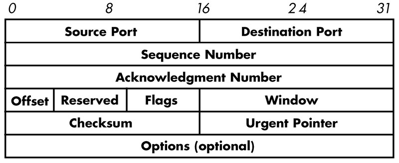
Figure 5. TCP header details.
The header is a block of information contained in a network message that provides important information to the application processing the message.
One of the fields in the TCP header is the checksum field. This field stores a 16-bit number that is generated by adding all of the values represented by the TCP data together, ignoring any carries out of the 16th bit position. The 1s complement of the final sum is saved as the checksum. For example, if the sum was the 3C85 hexadecimal, the 1s complement checksum would be C37A hex.
When a TCP message is received, its checksum is recomputed by adding all of the received data plus the checksum. Typically, the result must equal the 0000 hexadecimal (2s complement checksum) or the FFFF hex (1s complement checksum). If the checksum does not match, a message is sent back to the transmitter indicating that the data must be resent.
The checksum — together with acknowledgement messages — allows us to exchange data reliably. Checksums are also used to verify the contents of a file or EPROM or the contents of a line of text in a file used for downloading. For example, here is a text file encoded using Intel’s Hex record format:
:10200000310028D303DB03E680CA0520DB03E6109A
:0E201000C20320DB03E60F47D303DB03E680A9
:10201E00CA1A20DB03E610CA0320DB03D30317170B
:0C202E001717E6F0B04FCD0E02C30320E0
:00000001FF
The last byte on each line (9A on the first line, FF on the last) is the 2s complement checksum byte. If you add all the bytes on each line together, you should always end up with 00.
Whether we use hardware or software, protecting our data is becoming more and more important. It is worth the time spent investigating these, and other, techniques for error detection and correction. NV