In today’s world of social media and online funding, the step from electronics hobbyist to manufacturer is not that great. For many projects, it’s not hard to imagine selling a few hundred units in even the narrowest of niches using nothing more than word-of-mouth promotion to online communities. Now, all of a sudden, your hobby is more than just a drain on time and personal finances — you’re cashing in.
Unfortunately, there’s one potential hiccup in this scenario, assuming you want to do it right: the need to demonstrate compliance with Federal Communications Commission (FCC) emission rules. As a hobbyist, FCC rules aren’t something you’re likely to worry much about since you’re allowed to build up to five devices of a single design for personal use with no testing whatsoever.
Once you go over five units, however, things change. At this level, the FCC requires verification of any electronic device operating above 9 kHz since it could possibly produce unwanted interference to other local devices. Devices that do not use radio transmitters are referred to as “unintentional radiators,” and the testing bar is lower for them than it is for “intentional radiators” — devices that include radios like Wi-Fi modules or Bluetooth.
There are a few exceptions for some specialized applications, and you may be able to avoid FCC requirements by declaring that your product is a subassembly or a kit of some sort. In almost all other cases, hobbyists who want to bring electronics products to market in some form or another are subject to the rules set forth in Part 15 of Title 47 CFR.
It’s tempting to just skip FCC testing and hope no one complains, but it’s a risk that can come with major consequences. If you ship a product without an FCC number from an approved FCC lab, you can be fined up to $10,000 per day per device, plus a year in jail if the FCC decides you did it intentionally.
Unfortunately, the cost of demonstrating compliance can be steep as well. Devices that require verification or a “Declaration of Conformity” — that is unintentional radiators — can be tested for a few thousand dollars. For intentional radiators, the certification costs can range from $10,000 to as much as $30,000. Costs can escalate quickly if your product fails, and FCC compliance test reports usually offer little to no insight into the causes of a no-pass.
Get Ahead of the Curve
The best bet for avoiding these unpleasant scenarios is to perform FCC pre-compliance testing on your soon-to-be product before sending it off to the test house. The advent of low cost USB based real time spectrum analyzers from top-tier manufacturers means that pre-compliance testing is now within reach for even the most budget-strapped hobbyist or entrepreneur.
Pre-compliance testing gives you the opportunity to catch compliance problems early, and greatly improves the probability of a successful first pass of full EMC compliance testing without re-design. It also lets you identify problem areas early on, and then evaluate the effect of modifications as your design evolves from prototype and moves into production.
Since pre-compliance testing is not required by the FCC, the equipment used can be noncompliant and have lower accuracy and dynamic range than the compliant receivers used by approved labs if sufficient margin is applied to the test results. Pre-compliance testing requires the following test equipment:
- Spectrum analyzer with peak detector (quasi-peak optional)
- Preamplifier (optional)
- Antenna with non-metallic stand for radiated emissions
- Line impedance stabilization network (LISN) for conducted emissions testing
- Power limiter for conducted testing
- Near field probes for diagnostics (optional)
Radiated Emissions Testing
An intentional radiator is any device that broadcasts radio energy (not infrared or ultrasonic energy) to perform its function. Devices that are intentional radiators are also subject to unintentional testing requirements. Emissions at frequencies other than what the device is designed to use can occur because of internal circuitry.
When evaluating spectrum analyzers for this type of testing, it is important to select an instrument that can capture at least the third harmonic (if not more) of the radiated signals being generated within the device. The test setup for an intentional radiator is essentially the same as what’s used for radiated emissions testing. However, the frequencies of interest are limited to the radiated frequencies and frequency masks defined by the specifications, such as Wi-Fi, Bluetooth, etc.
After you have the equipment lined up, the next problem you’ll face is where to test. From an RF perspective, it’s noisy out there. Anechoic chambers like what the FCC labs use are prohibitively expensive. Fortunately, good results can be obtained from basements, conference rooms, or from rural locations. If possible, be sure to turn off local Wi-Fi, Bluetooth and cellular transmitters.
Figure 1 shows a block diagram of a typical setup for radiated emissions testing.

FIGURE 1. Be sure to select a location that will minimize external signal noises for radiated emissions testing when using a setup such as this one.
In this example, three very low cost printed circuit board (PCB) log periodic antennas and a biconical antenna were mounted on a tripod for easy placement, and the antenna factors (AF) and cable loss information was entered into the spectrum analyzer for field strength correction. A biconical antenna was used for the 20 to 200 MHz frequencies.
The longer 20 to 200 MHz wavelengths require a larger antenna, and the background noise becomes more of an issue as it includes many radio broadcast frequencies.
Pre-compliance testing is often done at different distances from your device, such as one meter and a few centimeters. Reducing the distance between the device and the test antenna increases the ratio of the device’s signal strength to RF background noise. Unfortunately, near field results do not translate directly into the far field tests used in EMI (electromagnetic interference) compliance testing, so be careful about drawing conclusions. Adding a pre-amplifier is another good way to boost signal levels relative to external noise.
Prior to turning on your device, take a minute to evaluate and characterize your test environment. Is there enough signal room between the limit line and your ambient noise floor? Are there known signals that can be reduced? Do you need to move your test setup to a quieter environment?
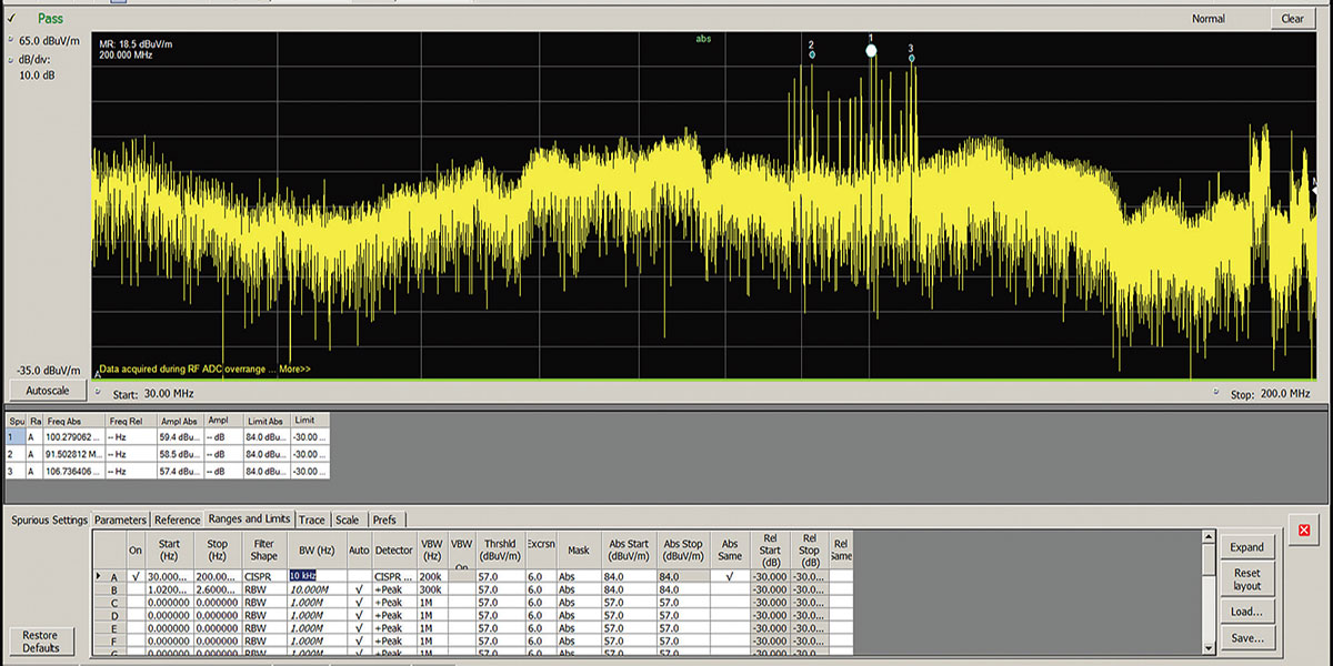
Once you are satisfied that your background noise won’t present a major problem, power-up your device. The differences between the two measurements are the emissions from the device as shown in Figure 2.

FIGURE 2. Broadcast signals are clearly visible in the VHF band; however, no out of limit conditions were attributable to the device in this example.
In this example, a Wi-Fi demo board that had already been through EMI compliance testing was evaluated, so there were no failures to detect.
If you have set up your testing correctly and nothing comes close to the limit line, it may mean that you are ready for compliance testing.
Unintentional Radiator Testing
Figure 3 shows the pre-compliance setup for conducted emissions testing.
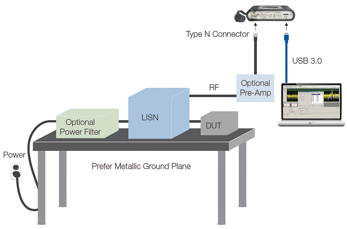
FIGURE 3. An LISN is used for making conducted radiation measurements.
In this example, we’re testing a universal AC/DC power adapter for a laptop computer. For conducted measurements, instead of antennas you use an LISN; essentially, a low pass filter which is placed between an AC or DC power source and whatever you’re testing to create a known impedance and to provide an RF noise measurement port. It also isolates the unwanted RF signals from the power source. Adding a pre-amplifier is a good way to boost the relative signal levels.
For conducted measurements, background noise often comes from the power source. While the LISN will provide some isolation, many times you will need additional power filtering. In this case, building power noise was a problem. By adding a power filter, the incoming noise was reduced to a low enough level for making conducted measurements.
In this example, it’s worth pointing out that the interference being conducted on a 60 or 50 Hz power supply also created issues. While most of the conducted EMI tests specify a measured frequency range of 9 kHz to 1 GHz, it can be useful to measure the signals at lower frequencies when the need arises.
For best conducted EMI measurement results, you should ideally use two LISNs: one for defined impedance to your device; and one to go to the spectrum analyzer or receiver. However, at least one LISN is a must.
Given that this was a low cost power supply, the conducted emission unsurprisingly went above the limit at approximately 172 Hz as shown in Figure 4.

FIGURE 4. Conducted emissions testing discovered an over-limit condition at the lower end of the spectrum in a low cost power supply.
Near Field Tools for Debugging
Far field tests can accurately tell whether a product passes or fails as a whole, but cannot pinpoint the source of a problem. Using only the far field test, you can’t isolate problems down to specific components or locations — like too much RF energy “leaking” from an opening in a metal enclosure or a cable radiating too much RF energy. The near field test is a good way to locate such emission sources and is typically performed using a spectrum analyzer and near field probe.
Near field probes are electromagnetic pickups used to capture either the electric (E) or magnetic (H) field at the area of interest.
Manufacturers provide kits of probes that offer the best compromise between size, sensitivity, and frequency range, and you may need all the sizes in your toolkit to solve your problem.
Selection between an H-field or E-field probe may be driven by the location of a signal in your design, or by the nature of its source (voltage or current).
For example, the presence of a metal shield may suppress the E-field, making it necessary to use an H-field probe for the application. Near field probes must be used to pick up the signal near the device under test.
Summary
Most hobbyists don’t need to worry much about FCC rules and compliance testing. That is, until the hobby produces an interesting design with market potential.
Even for small-scale manufacturing, you risk running afoul of FCC rules around electromagnetic emissions without the stamp of approval from an FCC approved test facility.
Pre-compliance testing using low cost USB based spectrum analyzers can give you the confidence that your design will meet FCC requirements and you’ll sail through compliance testing the first time out. NV