Last time, we looked in detail at the Arduino alarm clock software on the PC side. Then, we looked at how date and time data are handled on PCs and microcontrollers. Finally, we began looking at the Arduino side of the software. Let's continue and dig a bit deeper into the software.
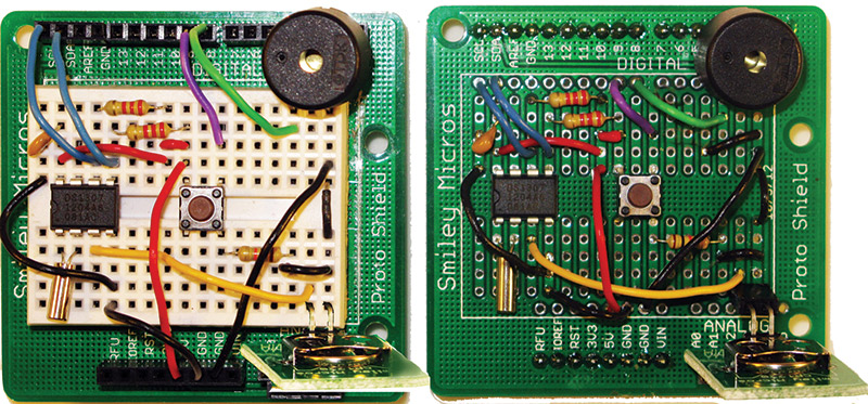
FIGURE 1. Proto shield alarm clock on breadboard and PCB.
The Alarm Data
As mentioned, last time we looked at how the dates and times are stored on the PC and began to look at how they are stored on microcontrollers. Since we are using the RTClib library for the DS1307, we will use some of that library's conventions for storing dates and times. As we saw back in Workshop 48, the DS1307 RTC (real time clock) keeps the dates and time in 10 bytes of binary coded decimal numbers. The RTClib provides a way to convert that into Unix time, which is a 32-bit number. So, we can store it in four bytes.
We also have several other parameters associated with each alarm including the type of alarm, if the alarm is set, and if the alarm has tripped. We store these latter three pieces of information in three variables, each being one byte.
So, the total data for each alarm is seven bytes, which is shown for alarm 1 as follows:
uint8_t alarm1_dt1;    // first 8-bits of the 32-bit unix datetime<br />
uint8_t alarm1_dt2;    // second 8-bits of the 32-bit unix datetime<br />
uint8_t alarm1_dt3;    // third 8-bits of the 32-bit unix datetime<br />
uint8_t alarm1_dt4;    // fourth 8-bits of the 32-bit unix datetime<br />
uint8_t alarm1_type;    // the type of alarm<br />
uint8_t alarm1_is_set;     // is the alarm set?<br />
uint8_t alarm1_is_tripped; // has the alarm tripped?
Since we have five alarms, this pattern is repeated five times giving us 35 bytes to store. Fortunately, the Arduino has a simple EEPROM library that we can use for this. This library has three functions that let us write, read, or clear any byte in the EEPROM. To keep things simple, we will use a write_alarms() and a read_alarms() function that will write or read all five alarms at one go. The write_alarms() function follows this pattern:
void write_alarms(){<br />
    EEPROM.write(0, alarm1_dt1);<br />
    EEPROM.write(1, alarm1_dt2);<br />
    EEPROM.write(2, alarm1_dt3);<br />
    EEPROM.write(3, alarm1_dt4);<br />
    EEPROM.write(4, alarm1_type);<br />
    EEPROM.write(5, alarm1_is_set);<br />
    EEPROM.write(6, alarm1_is_tripped);
// alarms 2,3, and 4
    EEPROM.write(28, alarm5_dt1);<br />
    EEPROM.write(29, alarm5_dt2);<br />
    EEPROM.write(30, alarm5_dt3);<br />
    EEPROM.write(31, alarm5_dt4);<br />
    EEPROM.write(32, alarm5_type);<br />
    EEPROM.write(33, alarm5_is_set);<br />
    EEPROM.write(34, alarm5_is_tripped);<br />
}
The read_alarms() function follows this pattern:
void read_alarms(){<br />
    alarm1_dt1 = EEPROM.read(0);<br />
    alarm1_dt2 = EEPROM.read(1);<br />
    alarm1_dt3 = EEPROM.read(2);<br />
    alarm1_dt4 = EEPROM.read(3);<br />
    alarm1_type = EEPROM.read(4);<br />
    alarm1_is_set = EEPROM.read(5);<br />
    alarm1_is_tripped = EEPROM.read(6);
// alarms 2,3, and 4
    alarm5_dt1 = EEPROM.read(28);<br />
    alarm5_dt2 = EEPROM.read(29);<br />
    alarm5_dt3 = EEPROM.read(30);<br />
    alarm5_dt4 = EEPROM.read(31);<br />
    alarm5_type = EEPROM.read(32);<br />
    alarm5_is_set = EEPROM.read(33);<br />
    alarm5_is_tripped = EEPROM.read(34);<br />
}
What About Time Zones (TZ) and Daylight Savings Time (DST)?
Oh bother! Both TZ and DST are a pain for time keeping. They are political constructs and vary all over the place. Don't get me wrong here; they are good ideas for people and productivity, but for keeping track of time — not so much. I noticed the problem for our particular application when I suddenly saw that my Arduino alarm clock had lost an entire hour overnight — according to the PC, anyway.
Of course, all the clocks in my house had to be set back manually — that I'm used to — but what about my desire to be able to keep track of time on the Arduino automatically and have it cross-checked by plugging it into a PC and running the C# alarm clock application?
Then, it occurred to me that I might visit relatives three time zones to the west, so if I plug my alarm clock into my PC, is it going to be three hours off? How in the heck am I supposed to use the PC to set the time and keep it calibrated?
It just so happens that the C# DateTime class has all sorts of features for dealing with this on the PC, which gets it time base off the Internet and is pretty darn accurate. If we keep the Arduino plugged into a PC so that it will know when you change TZ or DST, then why even bother with the RTC module? Should we build some sort of comprehensive Arduino library to help us keep track of changes in TZ and DST? Sounds like a lot of work to me — especially when we have to factor in that different political entities deal with this in different ways. This might be worth the effort if our purpose here is to create some kind of universal stand-alone clock, but that isn't our goal.
Your bedside alarm clock probably doesn't know what TZ it is in or the state of DST, so you set those things manually. Should an inexpensive Arduino based alarm clock be any different? Maybe, but I want to keep it simple since our main goal is to learn about time keeping on a microcontroller, and the secondary goal is to build software for letting us track time and use the microcontroller to do things at specific intervals.
Fortunately, lots of folks have faced this problem before and use UTC (Coordinated Universal Time Code). [No, that isn't a misprint. The acronym disagreeing with the name is the result of an argument between English speakers who wanted to use CUT and French speakers who wanted to use TUC, with the usual result that nobody got what makes sense.] UTC time is the inheritor of the GMT or Greenwich Mean Time which was the British Empire's way of saying that we'd set all our clocks right there at the Royal Observatory in London and everybody else will bloody-well like it.
If you choose to use UTC, then you can apply conversions to get the locally accepted time in your politically specific TZ and DST. So, we are going to change our software to use UTC. The modification of the C# code for the PC side of the Arduino alarm clock application is minor:
labelUTCTime.Text = DateTime.Now.ToUniversal<br />
Time().ToLongTimeString();
So, to help us keep track, I've added an additional window so we can see UTC and local time on the PC side, while only displaying UTC on the Arduino side — see Figure 2.

FIGURE 2. Added UTC time to PC application.
How This Code is Organized
Using the external real time clock module (DS1307) to keep track of dates and times is the core of our project. However, there are several other things we need to do in the software that are more general housekeeping type activities in order to have a functioning alarm clock.
These include receiving commands from the PC that we will use to set the date, time, and alarms, and how we will process those alarms (which includes the types of audible signals we can emit and how we will process a user button press). Plus, of course, there is the usual Arduino front end.
All together, this gives us four fairly separable parts of the software:
- Alarm_Clock — Arduino front end
- Commander — PC command functions
- Date_Time — DateTime functions
- Process_Alarms — Process alarm functions
We could keep all this code on a single 'page' module like we've done before, but this project has a LOT of code and some of it — such as the command processing section — is generic enough that we might want to keep it separate. This gives us the added benefit that by making it generic, we can easily port the techniques for some other project that needs a command processor that communicates with a PC. So, for this project, it makes sense to divide our code into four separate modules, following the list shown previously.
The Arduino has a feature where you can keep separate modules in a single project. Each module is available in the editor through tabs at the top of the editor as shown in Figure 3.
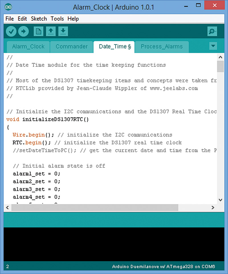
FIGURE 3. Arduino code modules.
Let's discuss the code in each module as separate items.
Alarm_Clock — Arduino Front End
The Alarm_Clock module begins with variable definitions and initializations, and by defining constants. These are used by the pushbutton debounce functions to initialize DateTime structures, to declare alarm states, and to set up PC communication constants, variables, and arrays. Of particular interest is the #define DEBUG definition. If this is left as is, then throughout the code debugging messages will be printed to the serial port. For example, in the Arduino setup function we have:
#if defined(DEBUG)<br />
  Serial.println("DEBUG mode");<br />
  pinMode(7, OUTPUT);<br />
  for(int i = 0 ; i < 5; i++){<br />
  digitalWrite(7, HIGH);<br />
  // turn the LED on (HIGH is the voltage level)<br />
  delay(250);              // wait for 1/4 second<br />
  digitalWrite(7, LOW);<br />
  // turn the LED off by making the voltage LOW<br />
  delay(250);         // wait for 1/4 second<br />
  }<br />
#endif
So, when the Arduino starts up it will send the 'DEBUG Mode' message to the PC and it will blink the LED five times. Once you are confident that the code works as you want it to, you simply put '//' in front of the define as follows: //#define DEBUG. Now, DEBUG will not be defined and the debug messages will not be printed. I've left this in the final code since I assume this alarm clock software will be heavily modified by folks wanting to apply it to specific situations, such as using it in a data logger.
The Arduino loop() function holds three key concepts for this program. First, it processes messages from the PC by checking to see if any serial characters have arrived, and if so, it calls the loadMessageArray() function that deals with PC messages.
Second, it processes alarms by checking to see if the check_alarm flag has been set (by a timer interrupt). If the flag is set, then it checks to see if any alarm is active. If one is, then it calls the associated function for that alarm. After checking the alarms, the flag is set back to 0, allowing the loop() to loop until the next time the timer sets the flag. This flag is set once per second.
You might think it would make sense to just check each alarm on each pass of the loop, but doing that will quickly overwhelm the system. So, checking them once per second leaves time to do other things in the loop(). Alarms are on one-second boundaries, so it makes little sense to check them more often. One second might not seem like much, but your Arduino will do nearly 16 million instructions in a second. So, it has lots of time to get other things done between possible alarm changes.
Third, the loop checks to see the state of the pushbutton. It uses a debounce method to make sure the button is really pushed, and that we aren't accepting glitches or button bounces as press release sequences. The debounce button state — either on or off — is shown on the LED.
Commander — Command Functions
The Commander module is a generic command processor for receiving commands from a PC application, like the alarm clock one we discussed in some detail last month. This application structures command strings that it then sends to the Arduino alarm clock program, which interprets and acts on those commands.
The command parser is rather simple-minded and uses a series of case statements to analyze the incoming message. For our particular application, we terminate each message with an exclamation mark '!' character and separate parts of the message with a comma ',' character. These are defined at the top of the Alarm_Clock module under TERMINATOR (the '!') and SEPARATOR (the ','). You can change them as needed for your particular application.
In the main Arduino loop() function, the loadMessageArray() function in the Commander module is called. It loads the message array with the most recent characters from the PC and then checks for the terminator symbol. If it is found, it then calls the parseArray() function. If it isn't found, it returns and the loop() continues with the next function. This allows messages to come in piecemeal, and lets the Arduino do other stuff while the message is coming in. Let's look at the parseArray() function:
void parseArray()<br />
{  <br />
  int i = 0;<br />
  int j = 0;<br />
  while( (messageArray[i] != TERMINATOR) && (i <<br />
  MAX_MESSAGE) )<br />
  {<br />
    while( (messageArray[i] != SEPARATOR)<br />
    {<br />
      commandArray[j++] = messageArray[i++];<br />
    }<br />
    commandArrayCount = j;<br />
    parseCommand();<br />
    j = 0;<br />
    i++;<br />
  }<br />
  messageArrayCount=0;<br />
  initializeMessageArray();<br />
  // Clear the receive buffer before going back<br />
  // to the loop()<br />
  while(Serial.available()) Serial.read();<br />
}
This function runs two while loops: the first guards against over-running the maximum message size and stops at the terminator; the second separates out the leading command and calls the parseCommand() function which runs a case statement against the command's first character. If a command has more than one character, the function called for the first command runs another case statement for the second character in the command and so on, until the full command is parsed. For example, we use two commands with the same first character: MI and MO. [These are educational examples only since they merely report to the PC that they have been called.]
The following code snippets show how this is done:
// Parse a command from the PC and call the<br />
// function<br />
// associated with the command<br />
void parseCommand()<br />
{<br />
  switch (commandArray[0])<br />
  {<br />
     case 'A': // Set Alarm # 1 to 5<br />
       ACase();<br />
       break;  <br />
      OTHER CASES<br />
      case 'M': // Minute (MI) or Month (MO)<br />
       MCase();<br />
       break;<br />
      OTHER CASES<br />
  }<br />
}<br />
LATER IN THE CODE:
// Minute (MI) or Month (MO)<br />
void MCase(){<br />
#if defined(DEBUG)<br />
  Serial.println("MCase");<br />
 #endif<br />
   switch (commandArray[1])<br />
  {<br />
     case 'I': // Minute<br />
       MICase();<br />
       break;<br />
     case 'O': // Month<br />
       MOCase();<br />
       break;<br />
      default:<br />
       Serial.println("MCase Bad command<br />
       Array[1].");<br />
       break;   <br />
  }<br />
}
// Minute<br />
void MICase(){<br />
#if defined(DEBUG)  <br />
  Serial.println("MICase");<br />
#endif  <br />
}
// Month<br />
void MOCase(){<br />
#if defined(DEBUG)  <br />
  Serial.println("MOCase");<br />
#endif<br />
}
There may be 'better' (more general) ways to parse commands, but this is about the simplest I know of and is sufficient for our purposes.
Date_Time — DateTime Functions
Last time, after discussing how dates and times are handled by computers, we decided to use Unix concepts as the basis for keeping track of dates and times. The Date_Time module has the functions we'll need to keep the data, and to receive it from and send to the PC. Some of the functions are simple, such as:
void show_time()<br />
{<br />
    DateTime now = RTC.now();
    Serial.print("TIME");<br />
    Serial.print(now.hour(), DEC);<br />
    Serial.print(':');<br />
    Serial.print(now.minute(), DEC);<br />
    Serial.print(':');<br />
    Serial.println(now.second(), DEC);<br />
}
This function reads the RTC, loads a DateTime type variable with the current time, and then sends it out the serial port.
Setting the Date and Time
It is a bit more complicated to set the date and time on the RTC using data from the PC. The PC application has the following line of code for sending the datetime string to the Arduino:
serialPort1.WriteLine("P" + _UnixTimeSpan.Total<br />
Seconds.ToString() + '!');
This arrives at the Arduino as the command string: "P################!" where all the '#' are the Unix seconds since inception (as discussed last month). The data is processed by the setDateTimeToPC() function:
void setDateTimeToPC(){  <br />
 int i;<br />
 uint32_t myUnixTime = 0;<br />
 uint32_t mult = 1000000000;<br />
 for(i=1;i<=10;i++){<br />
   Serial.print(commandArray[i]-48,DEC);<br />
   myUnixTime += (commandArray[i]-48) * mult;<br />
   mult = mult/10;<br />
   if(commandArray[i] == '-')break;<br />
 }<br />
 Serial.println("*\n");<br />
 Serial.print(myUnixTime,DEC);<br />
 Serial.println("^\n");<br />
 <br />
 RTC.adjust(myUnixTime);<br />
}
The setDateTimeToPC function takes these # characters and subtracts 48, thus converting the ASCII character for the number into the actual number (ASCII 48 is the character 0, so if the # is 48, then subtracting 48 yields 0, and since the remaining nine digits are sequential, that means 49 is '1.' Therefore, 49 - 48 = 1, and so forth.).
The function then multiplies each number by the multiplier (1000000000), and each subsequent number by the multiplier divided by 10, thus converting each character of the Unix datetime string into the numeric value represented by that character at that position. If this isn't clear, it might be a good idea to get a pencil and paper and follow the code presented. You'll then quickly see what is happening.
Once the character string is converted to a 32-bit number, that number is then sent to the RTC with the instruction to adjust the time to the value given.
Process_Alarms — Process Alarm Functions
The fourth module processes the alarm functions. However, we have run out of space again, so we will continue with this next month. Let's try not to lose track of what we are doing in the long run here. We are taking several articles to learn to do a complete Arduino-based design — both hardware and software — ending with our own custom-made (in Fritzing) alarm clock printed circuit board and robust software applications for it on the PC and the AVR. NV
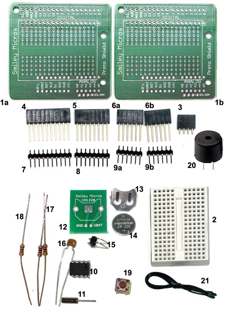
Arduino Proto Shield Alarm Clock Kit
This article is Part 3 in a series based on the Arduino proto shield alarm clock kit. This kit lets you build an alarm clock circuit on a breadboard and port that circuit to a PCB. This kit is the basis for my presentation of how to do a complete Arduino design cycle using Fritzing to go from a breadboard prototype, through schematic creation and breadboard layout, and finally producing your own printed circuit board. You can get the kit or materials that support this learning activity from the Nuts & Volts webstore.