In the fast moving world of digital electronics, I find it incredible that the vacuum tube — a piece of early 20th century analog technology — has managed to survive. It should have bitten the dust long ago but that just did not happen, thanks in part to electric guitar enthusiasts and the Soviet and Chinese militaries who kept using them.
The former were enamored with the sound of tube amplifiers, and the latter wanted their electronic equipment to survive a nuclear attack. Not only did the lowly vacuum tube make it into the 21st century, it is now on a noteworthy rebound. Today, many vacuum tube types are readily available and at reasonable cost. These consist of "new old stock" left over from 50 plus years ago, and many newly manufactured in modern plants world wide.
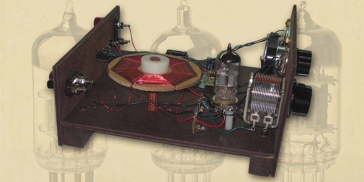
A past NV article describing how to revive an old tube amplifier inspired me to dust off my memories of past tube projects (some from 40 plus years back) and build a one-tube radio. The result was an exciting and fun project that I wanted to share. The radio is made using readily available parts, it operates on 12 volts making it perfectly safe, and it offers amazing performance for a simple one-tube design.
When I was growing up in the 1950s, my dad dabbled in radio/TV repair. His shop was strewn with all kinds of electronic parts. Add to this a small book of radio projects compiled from 1940’s issues of Popular Science Magazine and I was provided with many hours of experimentation and fun. I particularly remember a shortwave design with the intriguing title “Europe on One Tube.”
I am embarrassed to admit how many hours I spent trying to build radios based on these wonderful articles. Most of the designs used a regenerative circuit invented by Edwin Armstrong in 1912. A few years ago, I stumbled on an unusual regenerative design that operated on 12 volts — not the 100 or more of conventional tube designs. The radio I built turned out to be one of the best ever.
In this article, I will describe how to build and operate the broadcast band version. Should you decide to tackle it, I can promise you many hours of fun both in the building and in the listening for distant radio stations.
Vacuum Tube Background
Vacuum tube technology dates back to the time of Thomas Edison and the light bulb. In 1883, Edison noted that he could get electrons to flow between the hot filament of an experimental light bulb and a positively charged metal plate. The so-called Edison Effect only occurred in the near vacuum of the light bulb.
In 1904, the British scientist, John A. Fleming used the Edison Effect to produce the first practical tube, or “thermionic valve.” Fleming’s diode valve passed electrical current in only one direction, making it useful as a radio frequency detector and a rectifier for converting alternating current to direct current.
American inventor, Lee de Forest added a third element to the vacuum tube design and produced the triode, or “Audion” as he named it. He interposed a grid of wire mesh between the filament and metal plate that provided a way to control the flow of electrons.
The significant feature of his invention was that small changes of voltage on the grid would produce much larger changes of voltage on the plate, resulting in voltage amplification. Thus, a weak audio or radio signal could be amplified, which had many practical applications in telephone and radio communication.
As time went on, other advances were made in tube technology, including the addition of an indirectly heated cathode and other grids. For our purposes, the triode vacuum tube will serve as the heart of the regenerative radio receiver.
Regenerative Receiver Theory
Radio detector circuits take a variety of forms. The simplest is the diode detector mentioned earlier in relation to Fleming. When the triode came along, other detectors were invented including a design called a plate detector. When a radio signal was applied to the control grid of a triode, detected audio could be taken from the plate circuit. The regenerative receiver takes the plate detector one step further and adds a small amount of positive feedback, resulting in “regeneration” that substantially increases circuit gain and selectivity (ability to separate nearby radio stations).
The result is a very simple circuit consisting of only one tube and a handful of components that produce amazing results. Add a couple of stages of audio amplification and you have a radio design that provides hours of fun and listening pleasure!
Circuit Description
The basic circuit consists of a dual triode 12AU7. While this and other similar tubes are meant to operate at plate voltages of 90 volts or more, the 12AU7 performs amazingly well in the current application at only 12 volts. Dangerous voltages normally associated with tube projects are eliminated.
One disadvantage of low plate voltage operation is that it is not possible to develop sufficient audio power to drive a speaker or dynamic earphones. An LM386 IC power amplifier serves this purpose, making the overall design a hybrid mix of vacuum tube and semiconductor technology. The tube circuit consists of two sections: the regenerative detector and a low level audio amplifier. Refer to the schematic in Figure 1.
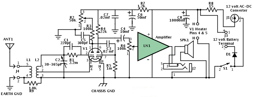
FIGURE 1. Schematic for the retro regen radio.
The radio frequency (RF) signal from the antenna (binding post J4) is applied to winding L1 of the spider web-wound coil. Winding L1 inductively couples the RF signal to a second winding L2 that — along with variable capacitor C1 — forms a resonant circuit covering the AM broadcast band (550 to 1600 kHz).
Capacitor C2 couples the tuned RF signal to the control grid of the triode V1-A. Resistor R1 provides a DC path to ground and “leaks” electron charge that would otherwise build up on the control grid and prevent the tube from working. A tap on winding L2 provides a small amount of positive feedback that, in turn, creates the regeneration needed to increase the gain and selectivity of the detector circuit.
Circuit gain and regeneration is controlled by varying the plate voltage of V1-A with potentiometer R3 and plate resistor R3. Capacitor C5 bypasses any remaining RF signal on V1-A’s plate to ground, while C3 couples the detected audio frequency (AF) signal to the control grid of V1-B. Resistor R5 provides a grid leak path as described previously, and establishes a small reverse operating bias on the control grid. V1-B acts as a small signal audio amplifier with a gain of five. The amplified signal on the plate is coupled to the volume control R6 by capacitor C4.
From the volume control, the AF signal passes to the audio amplifier module LN-1 that boosts it to speaker volume. Earphone jack J2 is wired so that speaker SPK1 is bypassed if an earphone is plugged in. Power is provided by either a 12 volt battery (binding post J3) or an AC-to-DC power supply (jack J1). Diode D1 prevents current from flowing back into the battery should an AC-to-DC supply be plugged in at the same time as a battery. Resistor R8 and capacitor C8 provide AC hum filtering needed for the AC-to-DC power supply. Resistor R7 and capacitor C6 provide additional AC hum filtering for the more sensitive V1 circuits.
Construction and Testing
Construction is divided into three stages, namely: constructing the chassis on which the circuit will be built; wiring the electronic circuit; and finally making the spiderweb coil. Some of the construction techniques employed may be new to readers. For instance, the chassis requires basic wood working skills, and the circuit is hand-wired rather than using a printed circuit board. Don’t worry; I will lead you through each and every step.
Constructing the Chassis
First, we will construct the chassis. Traditionally, radio chassis are constructed from aluminum or steel. Metal working has its own set of challenges and requires specialized tools, like expensive chassis punches. I chose instead to use tempered hardwood as a base for mounting components. Interesting, some of the earliest radios were built this way. (Refer to the image at www.duanesradios.info/html/scott_superheterodyne.html.)
Start with a 2’ x 4’ piece of 1/8” tempered hardwood. Cut a 7-1/4” strip across the 2’ width, then cut this piece at 7-3/4”, again at 4”, and finally at 3” (see Figure 2). These pieces are, respectively, the base, front, and rear assemblies of the chassis.
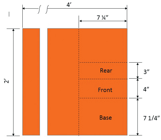
FIGURE 2. Hardboard sawing pattern.
To locate holes simply to be drilled, trim quad-ruled graph paper (four squares per inch) to fit each chassis assembly. Spray the reverse side of the graph paper lightly with spray adhesive and place the graph paper so that it lines up exactly with edges of the finished side of the hardboard. Press the graph paper down from the center out to remove an air bubbles and obtain a smooth result.
Use the layout drawings (Figures 3, 4, and 5; files are available in the downloads. Graphics shown here are for reference only.) to mark the drill locations and drill sizes on the graph paper. Note that holes for the audio module LN1, V1, C2, and binding posts J3 and J4 are located using the actual component to ensure correct hole location. Use an awl or ice pick to precisely locate where each hole will be drilled. If you plan to use an electric hand drill, pre-drill 1/16” pilot holes, then use the drill size specified. Clean up the holes by rubbing gently with medium sandpaper.
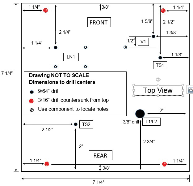
FIGURE 3. Base chassis drilling template.
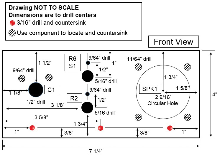
FIGURE 4. Front panel drilling template.
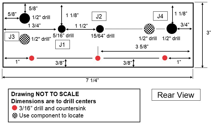
FIGURE 5. Rear panel drilling template.
The circular hole for the speaker will require a hole saw. Cut a 2-1/2” diameter hole first, then widen as necessary by sanding the circle edges so that the speaker rim gasket fits snugly into it. With the speaker in place, mark and drill its mounting holes.
Variable capacitor C2 also requires special handling. Place the shaft rim in the 1/2” drilled hole and note the two threaded holes on the front of the capacitor. From inside the capacitor frame, use a sharp pencil to mark the holes. Drill the holes and check that they line up correctly. Jacks J1 and J2 have thread lengths too short to reach through the 1/8” thick hardboard.
A simple solution is to use a flat tip 1/2” drill bit to carefully remove enough material from the back of the rear assembly to allow the threads to protrude sufficiently out the front side.
After all the holes are drilled, peel off the graph paper and clean the surfaces. This is a good time to apply a dark walnut stain if you desire.
Cut two 7-1/4” lengths of square dowel, then use 12 brass wood screws to attach the front and rear assemblies to the base. Use 1/8” pilot holes into the dowel to avoid splitting it (see Figure 6).
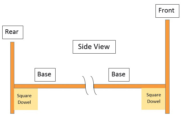
FIGURE 6. Side view of assembled chassis.
Mount all the components to the assembled chassis except for audio module LN-1 and the V1 socket. When satisfied with the fully assembled and populated chassis, remove the front and rear assemblies from the base.
Leave the base attached to the square dowels. Chassis construction is now complete.
Wiring the Circuit
The next stage of construction involves wiring the circuit. Mount the socket for V1 upside down on the base, using 3/4” standoffs and 6-32 x 1” machine screws. This will provide a convenient platform on which to pre-wire components associated with V1. If you are not experienced with soldering, search YouTube for “how to solder.” You can also refer to the series, “Basics of Soldering,” from SERVO Magazine (www.servomagazine.com).
Use Wiring Diagram 1 to wire components connected to V1’s socket. Wire the components in this order: connect the wire from pin 5 to pin 8 first; then connect R5, C3, and finally C5, layering one above the other. The remaining components and wires can be added in any order.
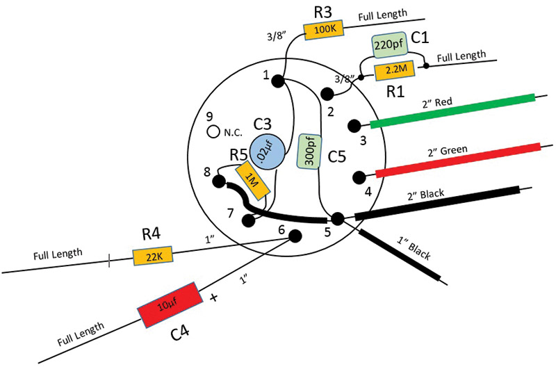
WIRING DIAGRAM 1. V1 socket wiring.
Follow the recommended lead lengths, allowing 1/4” additional to wrap around the connecting terminal for mechanical stability. For instance, if the lead length specified is 3/8”, cut the lead initially to 5/8” (3/8” + 1/4”). Use spaghetti wire insulation on all bare leads longer than 1/4”. Solder all connections.
When done, inspect all soldering joints, then remount V1’s socket right side up.
Before moving to the next stage of wiring, mount the front and rear assemblies to the base. Use Wiring Diagram 2 to connect the wires and components previously prepared on the V1 socket.
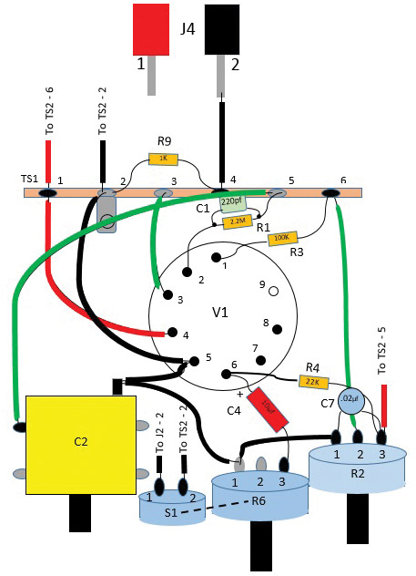
WIRING DIAGRAM 2. V1 and front panel wiring.
Now, add C7, R9, and the additional wires including those to terminal strip TS2 and J4. Trim wires and leads to their minimum length and use spaghetti wire insulation on all bare leads longer than 1/4”. When wiring is complete, solder the connections shown filled in with black; leave the gray connections for soldering later.
Use Wiring Diagram 3 to wire the power supply components. Trim wires and leads to their minimum length and use spaghetti wire insulation on all bare leads longer than 1/4”.
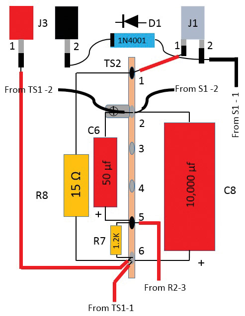
WIRING DIAGRAM 3. Power supply wiring.
When wiring is complete, solder the connections shown filled in with black; again, leave the gray connections for soldering later.
The next step is to build LN-1: the audio amplifier module. Instructions are included with the kit. A few changes must be made. Do not install the microphone or the 3.3K ohm resistor (LN-1 R1).
Also, replace the 1K ohm resistor (LN-1 R2) with a 100K ohm, and the 10K ohm resistor (LN-1 R3) with a 680K ohm. The change is necessary to decrease LN-1’s loading effect on V1-B’s output.
Add external wires to LN1 as indicated on Wiring Diagram 4, adhering to the color codes. Make all wire lengths 6” initially. Note that the input wires connected to the “MIC” point are tightly twisted for the first 3-1/2”. Adjust R6 (the LN-1 gain control) to maximum, fully counter-clockwise.

WIRING DIAGRAM 4. LN-1 audio module and speaker wiring.
After LN-1 is built, mount it to the base with 1/4” standoffs and 4-40 x 1” machine screws. Use Wiring Diagram 4 to wire audio module LN-1 to V1, the power supply, and the speaker/earphone circuit.
When wiring is complete, solder all connections.
Constructing the Spiderweb Coil
The final stage of construction involves making and installing the spiderweb coil. The fiberboard used as backing for picture framing is an excellent choice from which to make the coil. You may have to search around to find just the right material. The perfect selection will be slightly less than 1/8” thick and similar to (but not as hard as) the tempered hardboard.
Copy the pattern of Figure 7 and glue it to the fiberboard. Use a 3-1/2” circular saw to cut out the coil shape. The finished coil will be nearer the 3-1/4” diameter of the pattern. Use medium grade sandpaper to clean up the edges.
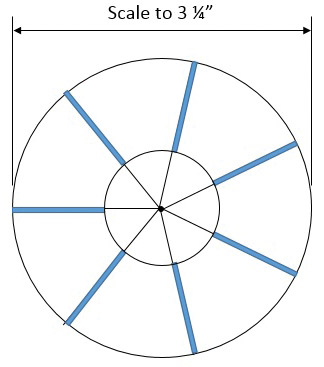
FIGURE 7. Template of spiderweb broadcast band coil.
While holding the coil in a vice, use a hack saw to cut the seven slits. After each slit is sawed, use medium sandpaper to clean it out and round the edges of the cut. This is most easily done by folding the sand paper in half and passing it back and forth within the slit.
Carefully check that the depth of each slit is the same. The circular saw will have made a hole in the center of the coil. Install a 1/4” x 2” long screw in the hole with the head against the smooth side. Secure it with a nut. You will wrap the coil leads around the extended threads of the screw to keep them out of the way while winding the coil.
To make winding L2, wind 5” of #28 enameled wire around the screw, then pass the remaining length through a slit. This will be lead 1. Pull it tight on the other side and pass it down through the next slit. Repeat this until you have made about 65 complete turns. Note that counting the wire turns on either side represents roughly half the total number of turns.
End winding with the wire passing back through the slit where you started. Fold the next 10” of wire in half, wrap it around the screw with lead 1, and pass the remaining wire through the same slit. The folded wire will be the coil tap lead 2. Continue winding in the same direction for about 13 turns, finishing at the same slit as before. Cut the wire to 5” and wrap this lead around the screw. This will be lead 3. Winding L2 is complete.
Leaving 5” leads, follow the same procedure for L1, starting and ending where you finished the L2 winding. Wind about five turns in the same direction. The starting lead is number 4 and the ending lead is number 5. When all windings are complete, dab a little quick set epoxy at the outer edge of the slit to keep lead 5 from unraveling.
Unwind the leads from the screw and gently pull them aside. Drill out the center hole to 3/8”. Cut a 3-1/2” length of 3/8” round dowel. Insert one end in an electric drill and sand the rotating dowel evenly until the nylon collars fit snugly over it. Cut 2-1/2” of the sanded portion and set it aside; refer to Figure 8.
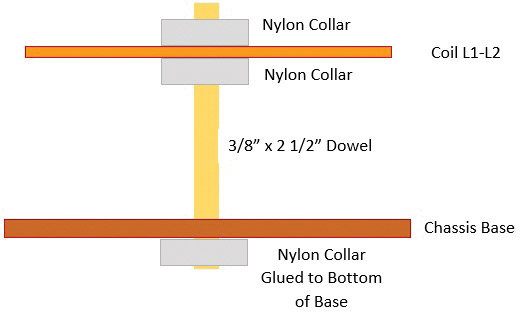
FIGURE 8. Side view of spiderweb coil assembly.
Glue a collar to the underside of the chassis base to hold the dowel firmly in place. Use Wiring Diagram 5 to connect the coil leads to terminal strip TS-1 and binding post J4. Solder all connections.
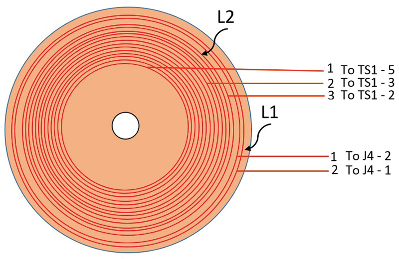
WIRING DIAGRAM 5. Spiderweb coil wiring.
Insert the dowel through the chassis base into the glued collar. Slip one collar on the dowel, then the coil (lead side down), and a second collar to hold the coil in place as shown in Figure 8.
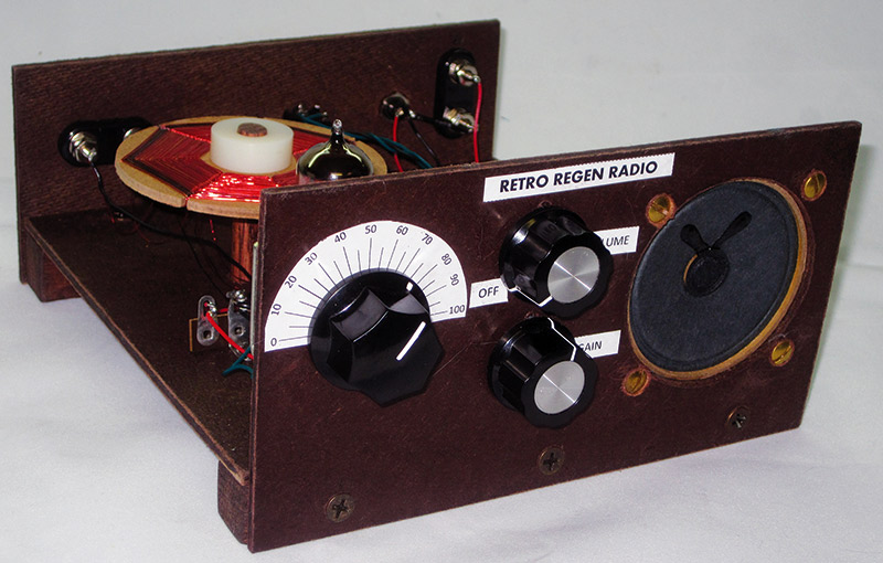
Use spray-on glue to attach the tuning scale and labels of Figure 9 to the front assembly. Lastly, install the knobs to the front of the radio. This completes construction.
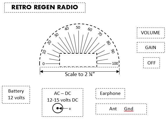
FIGURE 9. Tuning and other front panel labels.
Preliminary Testing
Before applying power the first time, it is a good idea to check for a major short circuit. Before inserting tube V1, turn the radio on with the volume control. Rotate the gain control fully clockwise. Use an ohmmeter to measure resistance between pins 1 and 2 of J1. After a few seconds, it should read 1,000 ohms or higher. A low reading (less than 100 ohms) suggests incorrect wiring and should be investigated.
Next, insert V1 into its socket and repeat the measurement. Now, expect a low resistance of 27-30 ohms. When satisfied with these checks, you are ready for the “smoke test.” Turn the radio on and set the volume control, gain, and tuning dials to mid-position. Apply either a 12 volt battery or AC-to-DC source, and note whether the heaters in V1 glow a dull red.
After warm-up (about 30 seconds or so), you should hear static in the speaker. Rotate the gain clockwise until you hear a squealing sound, indicating that the regenerative detector has passed into full oscillation. Normally, you will operate with the gain set below this point. On especially weak signals or when full selectivity is needed, set the gain just below the point of oscillation.
Operation
In urban areas with strong AM stations, the spiderweb loop will be all the antenna needed. Best reception of distant stations will be at night using an outside antenna 25’ to 50’ in length in conjunction with an earth ground. Here again, the Internet will provide lots of advice on installing long wire antennas and earth grounds. Here’s a tip when finding really weak stations.
First, use earphones rather than the speaker to eliminate distracting sounds around you. Next, rotate the gain control until the radio just breaks into oscillation. As you rotate the tuning knob, you will hear whistles that are heterodynes or beat frequencies of the radio’s oscillation and radio stations. Rotate the tuning knob very slowly, and note that the beat frequency starts at a high pitch and decreases as you rotate the tuning knob. When the pitch is very low or disappears completely, you are tuned directly on the station’s frequency. If you tune too far, the pitch will begin rising.
When “on frequency,” reduce the gain until the detector just falls out of oscillation, and you should hear the station. It will likely be weak and fade in and out, so you will have to listen carefully to hear the station identification and get the call sign and location.
Circuit Modifications and Enhancements
My initial choice of frequency coverage was the AM broadcast band, but the radio can tune the shortwave bands by simply changing the spiderweb coil design. Figures 10A and 10B show a coil designed to cover the 4-14 MHz shortwave bands, including international broadcasts and amateur radio. It requires heavier gauge wire (#16) and larger slits in the spiderweb coil. Because of the very wide tuning range, you may have difficulty tuning signals precisely.
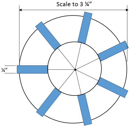
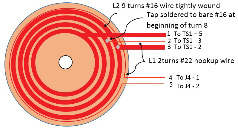
FIGURE 10. Template of spiderweb shortwave coil.
Shortwave receivers often have a second tuning capacitor of a much smaller value in parallel with the existing one. This “band spread” capacitor provides easier and more precise tuning once the general frequency is tuned with the main tuning capacitor.
Rather than adding another variable capacitor, a varactor diode could be used with the band spread tuning accomplished by a potentiometer controlling the reverse voltage of the diode. I have not tried this yet, but see no reason why it wouldn’t work.
I hope you will enjoy building and playing the retro regen radio as much as I have. Though I have not accomplished it yet myself, maybe we will succeed finally in accomplishing the goal of “Europe on one tube!” NV
Parts List
| ITEM |
COMPONENT |
DESCRIPTION |
|
|
| C1 |
220 pF @ 500 VDC |
Silver Mica Capacitor 5% Radial Lead |
|
|
| C2 |
30-365 pF |
Variable Capacitor |
|
|
| C3 |
.022 mF @ 50 VDC |
Disc Ceramic Capacitor 20% |
|
|
| C4 |
10 mF @ 50 VDC |
Axial Capacitor 20%, 85C |
|
|
| C5 |
300 pF @ 500 VDC |
Silver Mica Capacitor 5% Radial Lead |
|
|
| C6 |
50 mF @ 50 VDC |
Axial Capacitor 20%, 85C |
|
|
| C7 |
.022 mF @ 50 VDC |
Disc Ceramic Capacitor 20% |
|
|
| C8 |
10,000 mF @ 16 VDC |
Axial Capacitor 20%, 85C |
|
|
| D1 |
1N4001 |
Diode Rectifier |
|
|
| J1 |
Power Connector |
Connector, Power, PC712A |
|
|
| J2 |
Phone Jack |
Stereo 2.5 MM, Tip Switch |
|
|
| J3 |
DC (Battery) Supply |
Binding Post - Dual Banana Red and Black |
|
|
| J4 |
Antenna Terminal |
Binding Post - Dual Banana Red and Black |
|
|
| L1 |
Coil - Primary |
See text. |
|
|
| L2 |
Coil - Secondary |
See text. |
|
|
| LN1 |
Amplifier |
Kit, SUPER SNOOPER - BIG EAR |
|
|
| R1 |
2M ohm |
1/2 watt Carbon Film Resistor |
|
|
| R2 |
50K ohm Potentiometer |
Linear 0.5 watt with Switch (S1) |
|
|
| R3 |
100K ohm |
1/2 watt Carbon Film Resistor |
|
|
| R4 |
22K ohm |
1/2 watt Carbon Film Resistor |
|
|
| R5 |
1M ohm |
1/2 watt Carbon Film Resistor |
|
|
| R6 |
100K ohm |
Linear 0.5 watt with Switch (S1) |
|
|
| R7 |
1.2K ohm |
1/2 watt Carbon Film Resistor |
|
|
| R8 |
15 ohm |
1 watt Carbon Film Resistor |
|
|
| R9 |
1K Ohm
100K Ohm
680K Ohm |
1/2 watt Carbon Film Resistor
1/2 watt Carbon Film Resistor
1/2 watt Carbon Film Resistor |
|
|
| S1 |
Part of R6 |
SPST |
|
|
| SPK1 |
Speaker |
Speaker, Square, Ferrite Magnet, 2.6", 4 ohm |
|
|
| V1 |
Vacuum Tube |
Dual Triode 12AU7 |
|
|
| PWR 1 |
AC-DC Supply |
Unregulated,12 VDC/750 mA |
|
|
| Qty |
Hardware |
|
|
|
| 1 |
Tube Socket for V1 |
|
|
|
| 2 |
3/4" Nylon Spacer #6 Hole |
|
|
|
| 2 |
#6-32 1-1/4" Machine Screws |
|
|
|
| 2 |
#6-32 Machine Nuts |
|
|
|
| 2 |
#6-32 Machine Lock Washers |
|
|
|
| 2 |
6 Lug Terminal Strip |
2nd Lug Ground |
|
|
| 2 |
#6-32 3/8" Machine Screws |
|
|
|
| 2 |
#6-32 Machine Nuts |
|
|
|
| 2 |
#6-32 Machine Lock Washers |
|
|
|
| 4 |
1/4" Nylon Spacers #4 hole |
|
|
|
| 4 |
#4-40 3/4" Machine Screws |
|
|
|
| 4 |
#4-40 Machine Nuts |
|
|
|
| 4 |
#4-40 Machine Lock Washers |
|
|
|
| 12 |
#8 5/8" Brass Wood Screws |
Flat Head |
|
|
| 4 |
#8-32 1/2" Brass Machine Screws |
Oval Head |
|
|
| 4 |
#8-32 Brass Machine Nuts |
|
|
|
| 2 |
#6 1/4" Flat Head Machine Screws |
Trim thread length to avoid contact with moving stator of C2 |
|
|
| 1 |
Solder Lug |
Attach to bottom of C2 |
|
|
| 1 |
#6 1/4" Flat Head Machine Screws |
Trim thread length to avoid contact with fixed stator of C2 |
|
|
| 1 |
1/8" 2'x4' Tempered Hardboard |
|
|
|
| 3 |
Nylon Spacer I.D. 3/8" x 3/8" x 1" |
|
|
|
| Miscellaneous |
|
|
|
|
| 200' |
#28 Enameled Magnet Wire |
|
|
|
| 100' |
#22 Hook-up Wire |
Black |
|
|
| 100' |
#22 Hook-up Wire |
Green |
|
|
| 100' |
#22 Hook-up Wire |
Red |
|
|
| 4' |
Spaghetti Wire Tubing |
1/16" Black Heat Shrink Tubing |
|
|
| 1 |
3/8" Round Dowel |
|
|
|
| 1 |
3/4" x 3/4" Square Dowel |
|
|
|
| 1 |
1-1/2" Control Knob |
Communication Type |
|
|
| 2 |
1" Control Knob
Wood Stain to Personal Taste
1/8" Picture Frame Backing |
Communication Type
|
|
|
Downloads
What’s in the zip?
Faceplate Diagrams
Drilling Templates
Sample Sound Wav