Squeeze More Ponies from Your Go-Kart!
Part 1 of this mini-series was also Nextion Part 3 (last issue), where we started designing a programmer for our Small Engine Ignition Timing Controller. So, consider this installment really Nextion Part 4. Now, we build the Tune and DataLog Pages.
The Art of Tuning
Since the mid-1990s when Bowling & Grippo released their open-source MegaSquirt stand-alone fuel injection and ignition timing controller, tuning tools and strategies have evolved. Many companies offer tuning software for OEM MCUs like Hondata, Diablo, and HP Tuner. Still others offer stand-alone MCUs to take 100% control of engine functions: MegaSquirt, Link, and MOTEC. Many books have been written on using these tools to improve performance. A couple examples are “Maximum Boost” and “How to Tune & Modify Engine Management Systems.”
Kart racing has a following, with some of the top contenders spending more on a race season than most of us spend on our daily driver. They add fuel injection, ignition timing control, and other features, squeezing 22+ HP from a 5 HP engine! The most effective HP/$ modification is an ignition timing controller.
In this installment, we’ll build on last issue’s Nextion programmer by adding a Tuning screen and Data Logger. To get up to speed, review Parts 1, 2, and 3, as well as the new Nextion Editor Guide.
Again, a huge “Thank You” to Patrick Martin of Nextion for his help.
Timing Table
Let’s reload our project from last issue. Click on page3 in the Page pane (top right) for our Tune Page. We need (8 x 4) 32 cells (Numbers) for our X-Y table, plus a cell for Dwell. We need a way to change these values, highlight the cell we are changing, and indicate which cell is actively influencing timing.
Grab a Number from the Toolbox and give it the following properties: vscope=global, style=border, font=1 (Arial_32), bco=65520, X=10, Y=280, W=45, H=30, with all other values at the default. From the top header, click on Copy, then Paste. With your mouse, place it (n1) just to the right of n0. Repeat this process for eight cells total.
Set all of them to Y=280. We want two pixels of space between each block. So for n1, X=57 (X=10 + W=45 + 2). Go through n2 >> n7 and just add 47 (W+2) to the previous X value: n2 X= (57 + 47) 104, n3 X= (104 + 47) 151... n7 X=339.
Select all eight cells, then Copy and Paste. You will get Numbers n8 >> n15. Position them so Y=240. All X values should be the same as our first row. Repeat for Y=200 (n16 >> n23) and Y=160 (n24 >> n31). We now have our skeletal X-Y table.
Next, let’s add labels. From the Toolbox, grab a Text (t0): font=1 (Arial_32), sta=crop image, picc=[backdrop], txt=RPM, txt_maxl=3, X=395, Y=280, W=75, and H=30. Add a second Text (t1) with the following changes: txt=Load%, txt_maxl=5, X=0, Y=120, and W=85. This tells us our X axis is RPM and the Y axis represents engine load (vacuum). Refer to Figures 1-4.
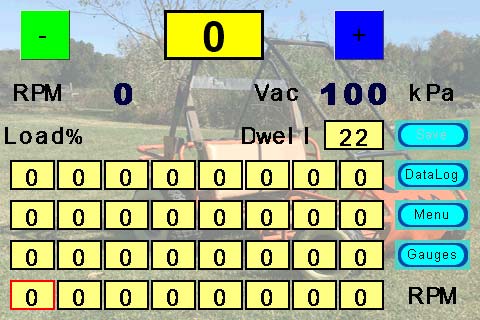
FIGURE 1. Tune Screen as opened.
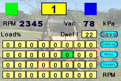
FIGURE 2. Data not saved, n21 selected, and n11 highlighted.
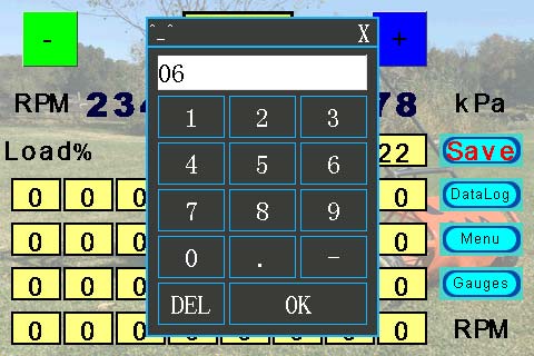
FIGURE 3. Keypad.
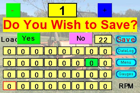
FIGURE 4. Do You Wish to Save?
We’ll need a cell for Dwell. Grab another Number (n32) from the Toolbox. Configure it the same as the other cells with the following changes: X=324, Y=120, and W=60. Grab a Text (t2) from the Toolbox to label our Dwell cell. Configure it the same as Load% but with these changes: txt=Dwell, txt_maxl=5, X=339, Y=120, and W=75.
We’ll need six variables and a timer. In the Attribute pane, rename va4 simply “X” and va5 “Y.” To change Pages, we’ll need some buttons. The first (b0): sta=image, pic and pic2=[generic button] (see Part 3), font=0 (Arial_16), pco2=63488 (red), txt=Gauges, txt_maxl=6, X=395, Y=240, W=75, and H=30. In the Event pane Touch Release(0) tab, type:
if(b3.font==0) //No changes Since Save
{
dp=2 //Goto Gauges Page
}else
{
vis t6,1 //“Do You Want to Save?”
vis b6,1 //Yes
vis b7,1 //No
va1.val=2 //Requested Page Number
}
From this code, it’s obvious we need more Tools. For now, grab another Button (b1) and set it up the same as the last one except: txt=Menu, txt_maxl=4, and Y=200. In the Event pane, copy Settings but change dp=2 to dp=1 and va1.val=2 to =1 (the complete code is in the downloads).
For the third Button (b2): txt=DataLog, txt_Maxl=7, and Y=160. In Events: dp=5 and va1.val=5, copying the rest of the code as-is. Note that the “Copy” and “Paste” features work with the Buttons the same as with Numbers.
Grab another Button (b3) and configure it the same, except: txt=Save, txt_maxl=4, pco=50712, and Y=120. In the Event pane, type:
prints 73,1 //Save Command
prints 1,1 //Save=1
b3.pco=50712 //Light Grey
b3.font=0 //Arial_16
This is our “Save” button. Prints is the Nextion command to send UART data; “73” is one of the commands we’ll create for our PIC (review Part 2).
Changing Values
We need a way to modify the values in our Table. We’ll use two methods: “+” and “-” buttons; and a keypad. To start, grab a Number from the Toolbox (n33). Give it the following Attributes: vscope=global, style=border, key=numeric keyboard\keybdB, borderw=3, font=2 (Arial_48_Bold), bco=65504, X=164, Y=10, W=100, and H=50. The selected nX.val will be displayed in this Number box.
For incremental changes, we need two more Buttons (b4 and b5). Set b4: bco=2016, font=1 (Arial_32), txt=- (the minus sign), txt_maxl=1, X=20, Y=10, and W and H=50. This should place a green button with the minus sign directly to the left of our n33 Number.
In the Event pane Touch Release tab, type:
if(n33.val>0) //Stay Positive
{
n33.val-=1 //Decrement our value
prints sys0,1 //Send Cell#
prints n33.val,1 //Send Cell.val
b3.pco=63488 //“Save” Button txt color=red
b3.font=1 //Arial_32
}
If n33>0, this Button will decrease the value by 1, then send the new value to our PIC controller. The cell number (nX) is stored in a non-volatile Variable sys0 (see the Editor Guide Section 6.15 for non-volatile variables). Next, we need a way to increment cell values. Back to the Toolbox for another Button (b5).
Configure like “-“ except: bco=31, bco2=33823, txt=+ (plus sign), and X=334. The Event pane code is also the same except: if(n33.val<25) and n33.val+=1.
When we click on a Table cell, its value is displayed in n33. Using the +/- buttons, we increment and decrement this value and send it back to the PIC. To make big changes quickly, we need ...
The Keypad
In the n33 Number Attribute pane, we selected vscope=global and key=numeric keyboard\keybdB; vscope=global means Numbers retain their value even when we move to another screen. (This was the setting for n0 >> n33.)
For key, we chose a numeric keyboard. You’ll notice in your Pages pane there is indeed a new keyboard: keybdB. Click on it. By default, it’s locked. In the top header, click on the unlock icon. Next, click on the “OK” Button b210 on the Keypad. In the Event pane Touch Release Event(48) tab, you’ll see a bunch of code. Count five lines down from the top where you will see covx input.txt.p[load.
Put your cursor at the end of that line and hit Enter to create a new line below it. Next, type: covx input.txt,sys1,0,0. This will allow us to convert the show (input) text value to a numerical value (covx), and put it in non-volatile variable sys1. It’s now available after the keypad closes and we return to the Tune Page.
When we open the keyboard, technically we’re closing the Tune Page. When we hit “OK” on the Keyboard, it closes and re-opens our Tune Page. Anything in Event Preinitialization/Postinitialization of our Tune Page will execute. Since we need to tell the PIC we changed something, that something is put in sys0/sys1.
Set Up Our Cells
Numbers n0 >> n32 are our Timing Table (and Dwell) values. We need the Nextion to do something when we click on a cell. This involves lots of copy/paste/modify code, but please follow along.
Start with the bottom left cell, n0. Click on it. In the Event pane Touch Press Event(35) tab, type:
n33.val=n0.val //Copy n0 Value to n33
sys0=40 //This is our Cell# for the PIC
n0.bco=2024 //Working Cell=green
n1.bco=65520 //All other cells=
n2.bco=65520 // Light Yellow
- - - - - - //Same code for n1 >> n32
n32.bco=65520
Copy/paste this code into the Event pane for n1 through n32, changing the first line to n33.val=nX.val; only the active cell should read nX.bco=2024. Additionally, sys0=40 needs to increment for each cell: for n1, sys0=41; n2, sys0=42 ... n32; and sys0=72.
Our UART decoding routine in the PIC will use that sys0 number to determine what it just received. Cell UART numbers range from 40 (for n0, cell0) to 71 (for n31, cell31) plus 72 (for n32, Dwell).
Lastly, copy n0.bco=65520 >> n32.bco=65520 to page3 Postinitialize Event, with all values =65520. This turns all cells yellow when returning from the Keyboard.
Commands and Global Variables
Take a look at the Nextion instructions. At the end are the various Errors and Information codes. It starts with 0x00 invalid and moves upward. There is no 0x07 or 0x08. In fact, there are lots of gaps. Notice that 0x24 is Serial Buffer Overflow, but the next entry is 0x65 — Touch Event. This gap offers 65 usable command codes we can assign as anything we want. With that in mind, here is the Command List used for this project:
0x25 (37 decimal): Command for PIC to send RPM, Vacuum, and Timing in rotation
0x26 (38d): For Data Logging, Change Data Send Rate
0x27 (39d): Send Complete Timing Table + Dwell
0x28 (40d): Timing Table [0], Nextion n0; First Cell
- - - - - - - - - -
0x47 (71d): Timing Table [31], Nextion n31; Last Cell
0x48 (72d): Dwell Value, Nextion n32
0x49 (73d): Save Command
0x68 (104d): Touch XY on Wake from Sleep
0x86 (134d): Sleep Mode
0x87 (135d): Awake From Sleep
Nextion offers Toolbox Variables (va0, va1, vaX), but they are Local. They only hold their value while on that page. If we want a Variable that’s available on other Pages, we need a Global Variable.
The Basic Nextion series has three: sys0, sys1, and sys2. When we open a new Page or activate the Keyboard, these Variable values persist. We are using sys0 for our Command Code and sys1 for the value itself.
When we send UART messages to our PIC (Part 6), it typically follows the for mat: sys0, sys1; Byte0, Byte1; Command Code, Value; Hin0, Hin1. In the code for n0, you see sys0=40. Now you know why.
Monitoring RPM and Vacuum
For tuning, we need to see RPM and Vacuum (kPa) values. Alas, we need two more Numbers and three more Text tools. Start with a Number (n34). In Attributes, change n34 to “rpm” to make our PIC software easier. The rest of the Attributes are: sta=crop image, font=2 (Arial_48_Bold), picc= [background], X=75, Y=70, W=100, H=47. For Vacuum, rename the next Number (n35) “vac,” and set it up the same, except: X=315, W=80.
For labels, we need a couple Text tools. For the first (t3): sta=crop image, font=1 (Arial_32), picc= [background], txt=RPM, txt_maxl=3, X=0, Y=70, W=75, H=47. For the next Text (t4), it’s the same Attributes except: txt=Vac, X=240. For the last Text (t5): txt=kPa, X=395, Y=77, W=75, H=30.
Highlight the Active Cell
Click on the tm0 Timer. In the Event pane, type the following:
if(rpm.val>600) //Engine is running
{
X.val=rpm.val/600 //Find X Cell Column number
if(X.val>7)
{
X.val=7 //Prevents Math Overflow
}
}else
{
X.val=0 //Engine not running
}
Y.val=vac.val/25 //We have 4 Rows
if(Y.val>3)
{
Y.val=3 //Prevents Math Overflow
}
va2.val=Y.val*8 //Each Row has 8 columns
va2.val+=X.val //Add our RPM X.Value (Offset)
va2.val+=7 //Nextion ID# Offset
for(va3.val=7;va3.val<39;va3.val++)
{ //Make All Cell Borders Black
b[va3.val].borderc=0 //Border=Black
}
b[va2.val].borderc=63488 //Active Cell Border=Red
The above code does nothing more than highlight the active Table cell in red, based on RPM and Vac (in kPa) values received from the PIC. The X.val=rpm.val/600 line reduces RPM to one of eight possibilities (capping at 4,800 RPM). Since we have four Y axis rows, Y.val=vac.val/25 yields four options. Each Y- row has eight X- cells, so: va2.val=Y.val*8 finds the active row in the Table.
Next, we add our X- (RPM) offset: va2.val+=X.val to get the exact cell. If vac>99 or if rpm>4799, a Nextion math error occurs, thus the if() filters.
va2.val+=7 requires some explanation. If you click on the bottom left cell (n0), the Attribute pane lists it as ID 7 (at least in the order I added Tools). Click on n1 and its ID is 8; n31 is 38. The line va2.val+=7 adds an offset to account for Nextion’s ID assignments. This is for pointers: b[va3.val].borderc=0 and b[va2.val].borderc=63488.
The b uses an ID number in brackets: b[va3.val]. We are using a for() loop to turn all of the borders black first; .borderc=0. Last, we turn our active cell border red: b[va2.val].borderc=63488. That’s all Timer (tm0) does.
CONSIDER THIS:
The bottom left cell is denoted as n0 with an ID of 7. For our UART protocol, it’s 40. In the PIC software, it will be known as “TimTab[0].” Think of it this way. To most folks, I’m Mike. My mother calls me Michael; my wife calls me hubby.
Strangers may address me as Mr. Holler, and I’m hoping eventually some little guy reaches for Pappy. Multiple names for the same thing (or person) is actually quite common.
Save
Before we go for a test drive, we need a safety net. Nothing worse than spending hours tuning, only to lose it because we forgot to save. Add another Text (t6): font=2 (Arial_48_Bold), bco=65504, pco=63488, txt_maxl=20, txt=Do You Wish to Save?, X=10, Y=60, W=460, and H=50. Next, we need two Buttons (b6 & b7).
For b6: font=1 (Arial_32), bco=2016, bco2=1024, pco2=63488, txt=Yes, txt_maxl=3, X=58, Y=112, W=80, and H=40. For the second Button (b7), use the same values except: bco=64543, bco2=8, txt=No, txt_maxl=2, and X=237.
Click on b6 and in the Touch Release tab of the Event pane, type:
prints 73,1 //Save Command
prints 1,1
dp=va1.val //Goto Requested Page
Click on b7 and type dp=va1.val. Refer to Figure 4.
Quick Test
Click on page3. In the Preinitialize tab of the Event pane, type:
prints sys0,1 //Command Code
prints sys1,1 //Command Value
vis t6,0 //“Do You Want to Save?”
vis b6,0 //“Yes”
vis b7,0 //“No”
if(sys0!=39) //Return from Keypad
{
b3.pco=63488 //Red
b3.font=1 //Arial_32
}
Remember from last issue we added sys0=39 to all Tune Buttons? That enabled us to tell the PIC to load the complete Timing Table plus Dwell. When we use the Keypad, we don’t want a total re-load, just the cell we modified. When we click on Table cell n0, the Touch Release code starts with sys0=40. So, when we return from the Keypad, only the new cell value is sent to the PIC.
Notice we aren’t actually changing the cell (n0 >> n32) value with Nextion code. When the PIC receives a new cell (TimTab[0>>31] and Dwell) value, it automatically mirrors it back to the Nextion. That changes the cell value. It’s a way of verifying the PIC received the new value. (Ignore the vis code for now.)
Click Save, Compile, and Debug. From the Menu screen, click Tune (refer back to Figure 1). Now, click on n0. It should turn green. Press the “+” button; “n33” changes from 0 to 1. Click again and it goes to 2.
In the lower right-of-center pane, you see what the Nextion is sending our PIC. Values are hexadecimal. When the Page first opened, the UART message was 27 01 (prints 39) telling the PIC to send the entire Timing Table plus Dwell. We wrote sys0=40 (decimal) and the UART transmission is 28 01 (40d=28h).
The Save button had light gray text with Arial_16 font. Once you clicked on n0 and “+,” the Save Button text turned red and grew to Arial_32 (see again Figure 2).
Click on n33 (our value display, top center) and the Keypad pops up. Click Del 6, then OK (Figure 3). When the Keypad disappears, we see “6” in n33; the UART sent 28 06 indicating the new value was sent to the PIC. Also, n0 is no longer green.
In the Instructions pane, type rpm.val=2345 (Enter), then vac.val=78 (Enter). Now n11 (up 1 over 4) is bordered in red. The RPM value reads 2345 and Vac shows 78 kPa (Figure 2).
Data Logging
Most tuning products offer data logging for later analysis. Nextion sports a Waveform tool to make this easy. Let’s build a data logger!
In the Page pane, click on page5. In the Preinitialize tab of the Event pane, type:
tm0.en=0
vis b6,0
vis b7,0
vis b8,0
vis b9,0
vis t3,0
vis t4,1 //Default 10X
vis t5,0
vis t6,0
From the Toolbox, add a Waveform (s0). Give it the following Attributes: dir=right to left, ch=3, gdw=40, gdh=40, pco0=63488, pco1=65504, pco2=2024, dis=100, W=480, and H=240. Next, add a Timer (tm0) and six Variables. Rename va3 “rpm,” va4 “vac,” and va5 “tim.” In the Event pane for tm0, type:
va0.val=tim.val*10 //Scales Timing
add 1,0,va0.val //Displays Timing on Ch0
va1.val=vac.val*2 //Scales Vacuum
add 1,1,va1.val //Displays Vacuum on Ch1
va2.val=rpm.val/20 //Scales RPM
add 1,2,va2.val //Displays RPM on Ch2
The Waveform scaling yields 0 >> 240 range (the way it’s configured). Timing values range from 0 to 25, so “*10” allows Timing to scale the entire screen top to bottom. Similarly, kPa ranges from 15 to 115. Multiplying by 2 allows it to fill the Waveform. Same concept for RPM.
Notice RPM answers to the same rpm.val= command no matter which Page is displayed, whether rpm is a Variable or Number. This makes PIC code easier, as does vac.val= and tim.val=.
Grab a Text (t0): sta=crop image, font=1 (Arial_32), picc=[backdrop], pco=63488, txt=RPM, txt_maxl=3, X=7, Y=240, W=80, and H=30. Add a second Text (t1) and configure it the same except: pco=65504, txt=Load, txt_maxl=4, and X=90. Add another Text (t2): pco=2024, txt=Timing, txt_maxl=6, and X=175 and W=110. These three Texts are the legend identifying the colored lines on the Waveform.
We need to add some page-changing Buttons. Add a Menu Button (b0) as we have already done on numerous occasions, with X=10 and Y=280. Add a Gauges Button (b1) with X=95 (same Y=280), and a Tune Button (b2) where X=180.
They line up along the bottom to the left. In the Touch Release tab of the Events pane, Menu (b0), type:
prints 37,1
prints 0,1 //Disable Data Send
dp=1
Gauges (b1): dp=2; and Tune (b2) type:
sys0=39 //Load Table Command
sys1=1
dp=3
Controls
Data logging requires the ability to start and stop recording, plus set the data acquisition rate. Grab another Button (b3), label it Start, and place it at X=310, Y=280. In the Touch Release tab, type:
tm0.en=1 //Start Timer
prints 37,1 //Rotation Command
prints 1,1 //Start
Add another Button (b4), label it Stop, and place it at X=395, Y=280. In the Event pane, use similar code as Start, but tm0.en=0 and prints 1,0 (Stop).
CHANGING RATE
Sometimes you want to capture a brief spurt with high resolution and a rapid refresh rate. Sometimes you just want trends over a longer duration with a slower refresh rate. Let’s add that feature.
Grab another (generic) Button (b5) and label it Rate. Put it at X=395 and Y=245. In the Touch Release tab of the Event pane, type:
sys0=38 //Change Rate Command
vis b6,1 //Show Rate Buttons
vis b7,1
vis b8,1
vis b9,1
tm0.en=0 //Disable Timer
cle 1,255 //Clear All Waveforms
The Command Code sys0=38 loads the “Change Send Rate” command into the Global Variable sys0. The vis commands show Buttons we will create. Turn the Timer (tm0) off tm0.en=0, and clear the Waveform data cle 1,255. Next, add another Button (b6): sta=solid color, font=1, bco=63504, bco2=64543, pco2=2024, txt_maxl=18, txt=20X per Sec (Fast), X=170, Y=10, W=300, H=40.
In the Touch Release Tab, type:
sys1=5 // X20=50 ms (Fast)
prints sys0,1 //Command Code: Rate Change
prints sys1,1 //50 ms
vis b6,0 //Hide the 4 buttons
vis b7,0
vis b8,0
vis b9,0
tm0.tim=50 //Waveform Refresh Rate = 50 ms
tm0.en=1 //Enable tm0
vis t3,1 //Show 20X
vis t4,0 //Hide 10X
vis t5,0 //Hide 5X
vis t6,0 //Hide 2X
Add another Button (b7) and set it up the same, but with the following differences: bco=65543, bco2=65504, txt_maxl=17, txt=10X per Sec (Med), Y=70. In the Touch Release Tab, copy the above code but change the following: sys1=10, tm0.tim=100, vis t3,0, and vis t4,1.
Next Button (b8): bco=33823, bco2=50712, pco2=65535, txt_maxl=16, txt=5X per Sec (Med), and Y=130. In the Touch Release Tab, copy the previous code and change: sys1=20, tm0.tim=200, vis t4,0, and vis t5,1.
For the last Button (b9): bco=34784, bco2=2024, pco2=63488, txt_maxl=17, txt=2X per Sec (Slow), and Y=190. With sys1=50, can you fill in the rest of the Touch Release code?
Rate Indicator
Let’s create an indicator(s) to show our chosen acquisition rate. Add another Text (t3) with the following Attributes: bco=63504, txt=20X, txt_maxl=3, X=270, Y=284, W=30, and H=22. Add another Text (t4) with all the same Attributes except: bco=64543 and txt=10X. Yes, size and location are the same as t3, but our Button (b6 >> b9) code shows and hides these Texts with the vis command.
Next, Text (t5) is the same except: bco=33823, txt=5X, and txt_maxl=2. Lastly, t6: bco=34784 and txt=2X.
We just added four Texts in the same spot, but only one will be visible at any given time, depending on the Waveform acquisition rate we select. When reviewing data, it’s nice to know resolution, which now we can.
Test Drive
Click Save, Compile, and Debug. From Menu, click on DataLog. When it opens, click the Start Button and type into the Instructions pane: rpm.val=2345 (Return), vac.val=34 (Return), tim.val=10 (see Figure 5).
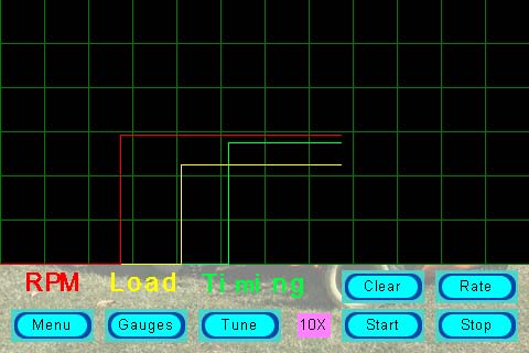
FIGURE 5. DataLog showing 10X logged values.
You’ll see the three lines scrolling across the Waveform. Change any of the values and watch the corresponding line change. Click Stop, then Rate. The Buttons for different rates will appear (see Figure 6).
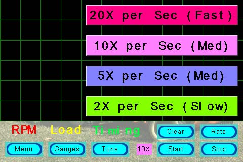
FIGURE 6. Rate change buttons.
Click on any one and watch what happens. Play with it, changing rate and individual values. The only thing missing is a Clear Screen Button. My son pointed that out when I asked for his input. Sooooo, let’s add another Button (b10).
Use the generic Button image and configure it to: txt=Clear, txt_maxl=5, X=310, and Y=245. In the Touch Release tab, add cle 1,255. Try it in Debug.
Conclusion
This wraps up the Nextion Programmer portion of the Small Engine Ignition Timing Controller. So far, we learned to add tools from the Toolbox and get them to do stuff (Part 1). Then, we learned how to talk to a PIC processor (Part 2). Next, we learned how to add pizzazz to the Nextion tools (Parts 3 and 4). Alas, we have created a rather capable programming tool.
Some additional thoughts: You could add resolution to the Timing Table with eight MAP rows, or even go to 16x16. You could also add timing retard.
Last issue, I added alternative Buttons and Gauge faces in the downloads for that article. If you haven’t already, check them out. With a larger Nextion screen, you can fit more “stuff” and/or make objects larger (easier to click and see).
With what you now know, you can create attractive touch screens for practically any project. Just be aware, the Nextion is not automotive rated (limited temperature range) or waterproof, and can be difficult to see in direct sunlight.
Next issue, we tackle the circuit board with all the controlling hardware (Part 5). Following that, we breathe life into our project with PBP3 PICBASIC PRO code (Part 6).
Finally, we bolt and wire everything to a real go-kart and take it for a “test thrash,” tuning as we go (Part 7).
A few things were omitted from this article, plus I probably typed a mistake or three; therefore the complete working Nextion code is in the downloads for this article. NV
Downloads
What’s in the zip?
Audio File