Bringing It All Together!
At this point, we have a Nextion touch screen programmer and an assembled and programmed PIC ignition timing controller. To wrap it up, we’ll install it on my son’s Manco go-kart to see how she runs!
Unfortunately, I can’t include blueprints, CAD drawings, or 3D printer software in the article downloads. I’m working with my son’s modified Manco two-seat go-kart. Chances are none of you will be working with the same platform, so the brackets I made wouldn’t work for you. Instead, I want to show you what needs to be done and how we did it. It’s up to you to make it work for your application.
Hardware
There are two critical items that you must have for your project: a 12 volt battery and an automotive ignition coil. Of course, to make them functional, you also need an ignition wire, mounting brackets, hook-up wire, connectors, a switch, fuses, nuts, bolts, brackets, and so forth.
For the battery, we chose a 12 volt 285 CCA lawn and garden lead-acid battery purchased from the local NAPA Auto Parts store for about $60 (including the core charge). I had considered possibly using lithium-ion or NiMH, but went with lead-acid for cost reasons. (Other battery options would have to include a printed circuit board [PCB] and battery holder costs.) You may opt for Li-Ion (or even super caps) to save weight and space on a racing kart.
The ignition coil is a dry E-cell 100:1 turns ratio version purchased from Jegs for around $25 (see the Parts List). It has a rated output of 60 kV, measures 0.8 ohms primary (0.450 ohms rated), and 3.40 mH primary. Jegs sells them under the ProComp PC91 label and the Streetmaster PC-91E label (the one we used). Any negative ground automotive ignition coil should work, though. Just be aware the Dwell setting used in the software was specific to this coil, and different coils may need more (or less) dwell.
You could measure the distance between where you mount the coil and the spark plug and buy a pre-made ignition wire from your local auto parts store (or even salvage a used wire from a previous daily-driver tune-up). We made a custom solid-core wire using Taylor 8 mm cut-to-fit silicon jacket wire.
The boots and terminals are Taylor 90 degree black silicon (see the Parts List). Solid-core ignition wires generate massive amounts of RFI. They haven’t been readily used on street vehicles since the 1970s (and then only for the aftermarket).
A trick I learned is to put a ferrite ring around the wire, close to the coil. (I run solid-core wires on our fuel injected ECU controlled Jeep Grand Cherokee using this trick.) For the kart, I’m using a 7.93 mm ID ferrite ring from Digi-Key. With a little WD-40, it slides right on the 8 mm wire (Figure 1).
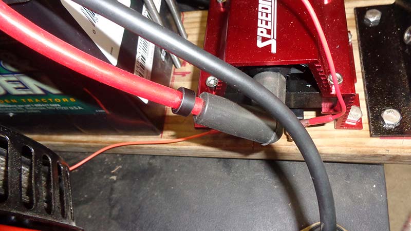
Figure 1. Taylor solid core ignition wire with ferrite suppressor ring and Taylor 90 degree silicon boot connecting Streetmaster PC-91E coil to spark plug.
A 10 amp toggle switch connects the fused battery 12 volts to the controller’s red power wire. We fabricated a sheet metal panel that mounts below the steering wheel for the switch; large enough to add more goodies later. When the switch is OFF, the controller is not powered, and therefore can’t drive the ground signal to the ignition coil (Figure 2). This becomes the new easy-to-reach kill switch.
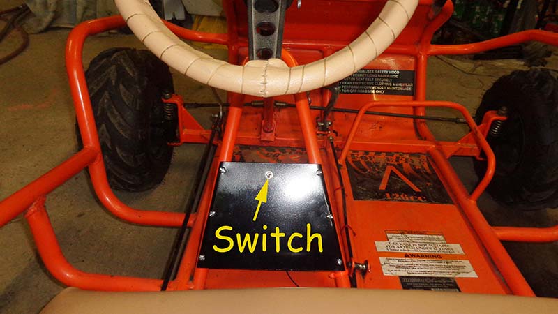
Figure 2. ON/OFF switch mounted in custom panel. Wires are routed along the center of the floor, pull-tied to the throttle cable.
I confess, I spent several months using a 5 HP Honda engine for testing and development (Figure 3).
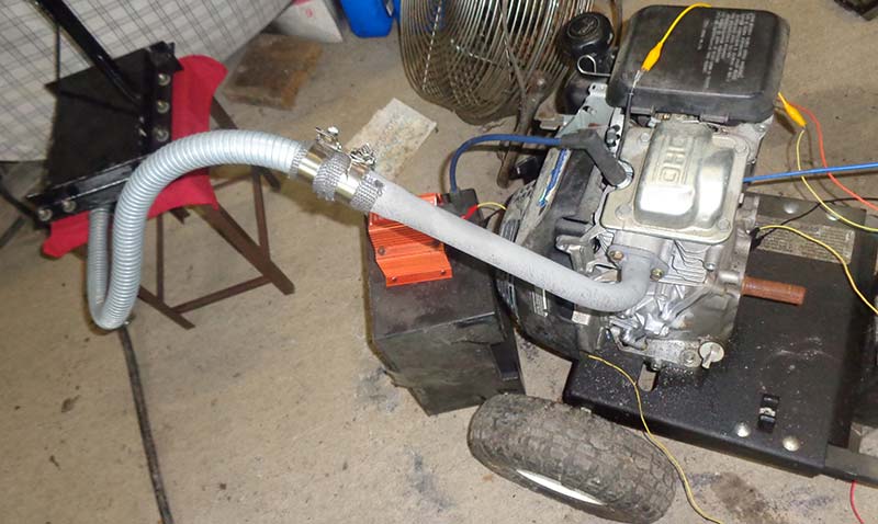
Figure 3. 5HP Honda engine used for development and emissions testing. Note extended exhaust pipe top right in the picture.
Initially, I wanted to keep things as simple as possible, so I used PBP3’s “ON INTERRUPT GOTO” Directive for the Interrupt Service Handler. (Normally, I would create ASM Interrupt Routines using DEFINE INTHAND ISR.) Charles Leo (ME Labs) just shook his head and laughed when I told him.
He informed me that ON INTERRUPT “polls” for Interrupt Flags and services them at the software’s earliest convenience. As a compromise, switching to DT_INTS solved many glitches. (See the previous installment for details.)
My son vividly remembers the Honda backfiring, bucking, coughing, and acting like junk as I was ironing out the bugs (remember ON_INTERRUPT). He has reluctantly allowed me to use his go-kart for the purpose of fulfilling the last installments of this article series. However, he didn’t want me cutting, drilling, welding, and powder coating special brackets to mount the battery, coil, and controller. Therefore, these items are mounted on a board clamped to the go-kart (Figure 4).
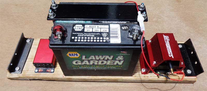
Figure 4. Added parts mounted to removable board. From left: controller, battery, and ignition coil.
In order to get a vacuum signal, we had to drill a hole in the plastic spacer between the carburetor and cylinder head to effectively tap the vacuum between the throttle plate and intake valve (Figure 5). This kept things reversible.
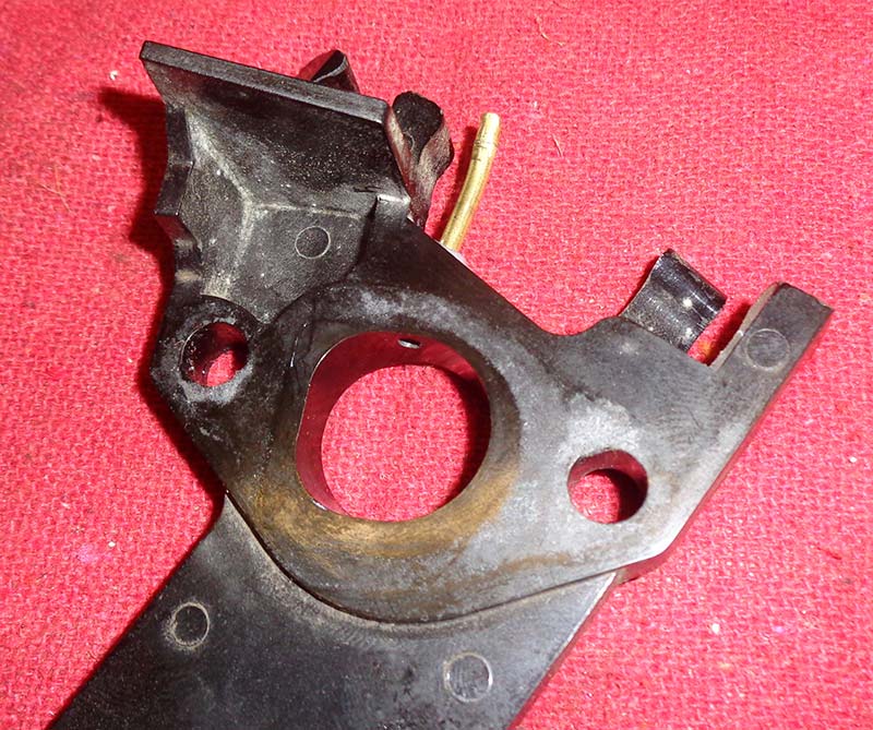
Figure 5. Plastic carb spacer modified with a vacuum port.
The Test Mule
As pictured many times in these articles, the test kart is a Manco two-seater that was originally powered by a 5 HP Subaru Robin engine.
We bought it for not much money and needing a lot of work. The engine was one of the upgrades we tackled getting it track ready.
It now sports a Harbor Freight 6.5 HP Predator engine. It has the “torque converter” which works just like the infinitely variable automatic transmissions found in the Subaru Justy and Jeep Compass. The seat was toxic with mold, so it has been totally rebuilt: new wood, foam, and vinyl covers. My son painted a Jack-O-Lantern face on the front and gave the tires a white-wall look (dubbed “The Great Pun-Kin”).
Other than that, rebuilding the steering, putting in a new drive belt and front tires, repairing stripped threads, and other things are basically maintenance repairs.
Modifying the Hammond PIC Controller Enclosure
We need holes to run wires through the Hammond controller enclosure, as well as for the vacuum tube; possibly for the programmer cable too. Initially, I ran all four wires (battery power and ground, magneto trigger, and coil driver) through the same hole in the enclosure end plate. What I found was that the RFI from the coil drive wire (orange) was scrambling the signal from the magneto (Figure 6).
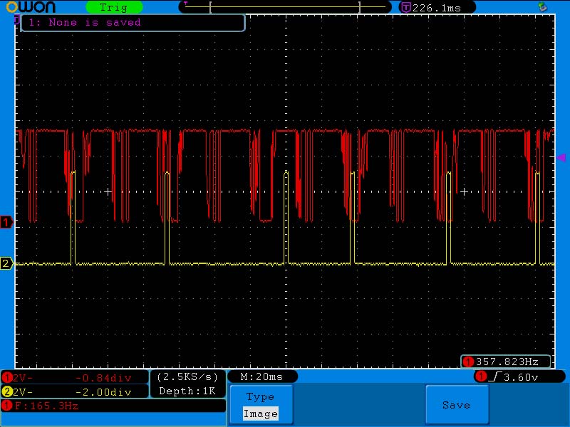
Figure 6. Ignition input signal (red) was noisy with wires bundled together; red is input from magneto “kill” wire; yellow is scrambled coil driver signal. Note altered coil (yellow) pulse near center.
I drilled a second hole in the enclosure end plate to isolate the coil driver wire, which cleaned up the input signal (see Figure 7).
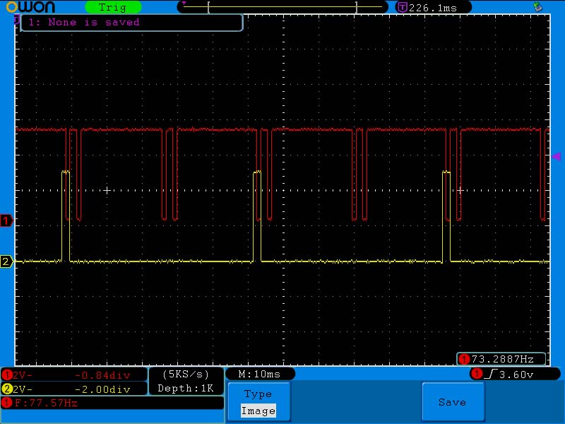
Figure 7. Clean ignition input with coil driver (orange) wire separated from the rest.
To prevent wire chafing and possible rub-through, I used rubber grommets from Harbor Freight (Figure 8).
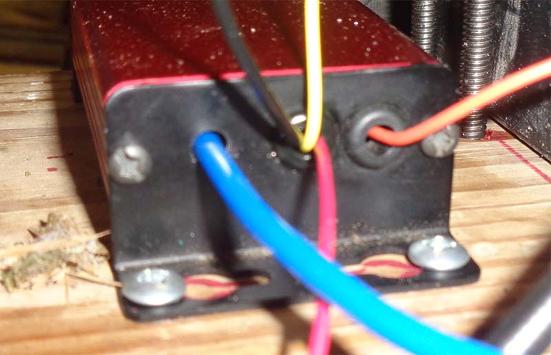
Figure 8. Controller with divorced coil driver wire (orange on right). Also note blue vacuum hose. Wires are protected by rubber grommets.
Adding a Vacuum Port
As already stated, we needed a vacuum port between the throttle plate and intake valve. On the Predator engine, there are three choices: the carburetor; plastic spacer; and the cylinder head. The cylinder head made it permanent (which was not the goal).The carburetor really has no ideal spot for the port. On one side, we have idle ports; on the other, the bowl vent passageway, and the throttle interferes up top. Therefore, the plastic spacer it is!
The OD of the brass tube measures 0.0945”. We used a #42 drill bit which measures 0.0935”, giving a slight 0.001” press fit. The tube was smeared with JB Weld to help it fuse with the plastic spacer. Cutting the brass tube without distorting it proved challenging.
I tried a hose cutter, but it still distorted. I tried a tubing cutter, but my smallest one was still way too big. Side cutters just pinched the tube. Ultimately, I just had to cut it (I used the hose cutter), then gently reshape it back into a round tube with pliers afterwards. Due to the slight press-fit, I used a small hammer to gently nudge it into the plastic spacer.
Referencing Figure 9, you can see a passageway in the carb side of the spacer that must be avoided.
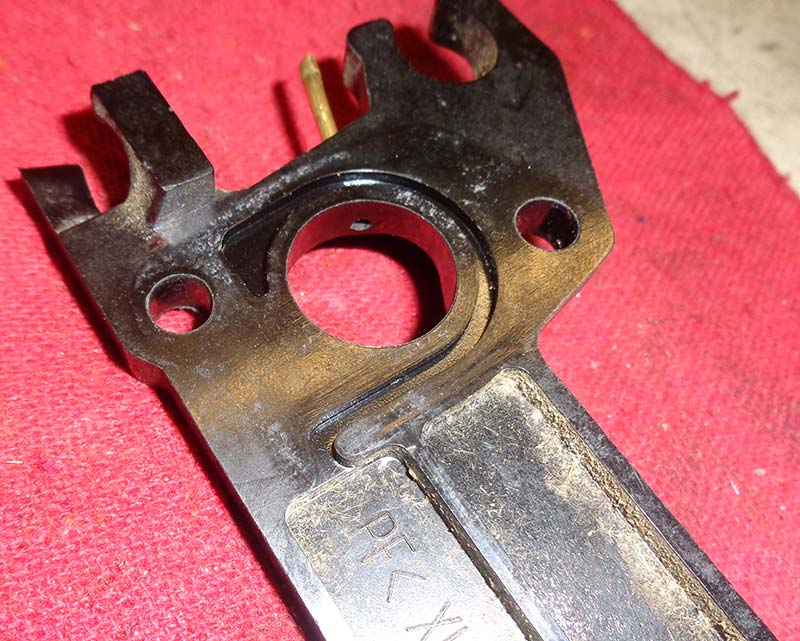
Figure 9. Note vent channel on carb side of plastic spacer. Drilled vacuum port must avoid that.
Clearance for the throttle arm must also be considered. Ideally, you want the port in the 10 o’clock to 2 o’clock range, up high. The worst place for it is in the 5-7 o’clock range.
As I found with the Honda test sled, a low lying port allows liquid fuel to accumulate and run down the hose. A 6 o’clock position caused raw fuel to run into the MPXA6115 vacuum transducer. Figure 10 shows our port in the 1 o’clock position.
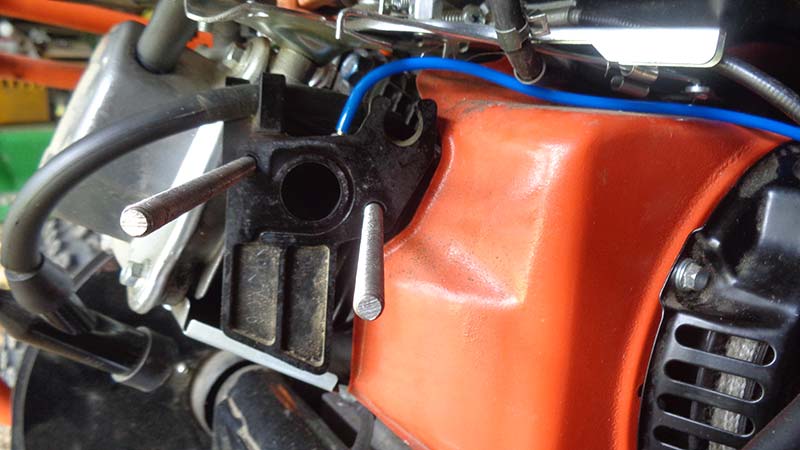
Figure 10. Modified plastic carb spacer mounted to intake with added port at 1 o’clock.
With the hose attached and carburetor in place, you can see there is no interference with the throttle mechanisms (Figure 11).
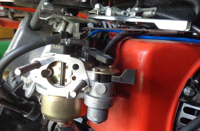
Figure 11. With carb installed, the blue vacuum hose is routed to avoid throttle interference.
As a safety note, when removing the carb, pinch or plug the fuel hose so you don’t get gasoline everywhere (Figure 12).
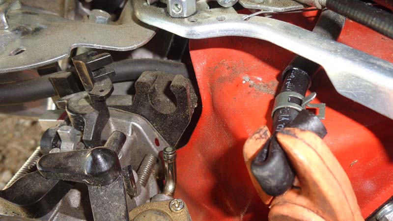
Figure 12. For safety reasons, plug fuel hose when removing the carburetor.
Use pull ties to secure the vacuum hose so it doesn’t get caught in the rip cord or throttle arm (Figure 13), and don’t forget to reconnect the PVC and tank vent hoses to the air cleaner on reassembly (Figure 14).
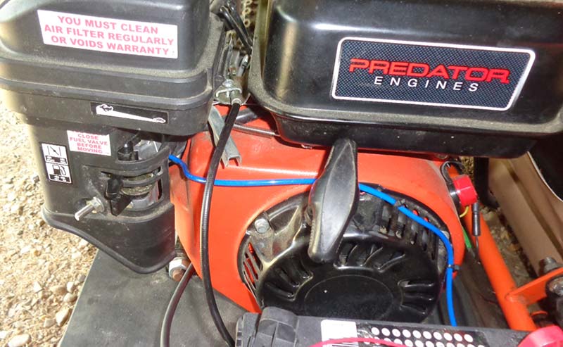
Figure 13. Plastic pull ties are used to secure the vacuum hose out of harm’s way.
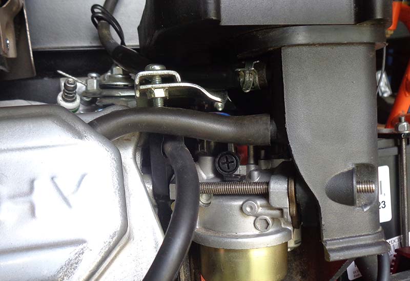
Figure 14. Don’t forget to reconnect the PCV and fuel tank vent hoses to the air cleaner on reassembly.
The Mounting
I cut a piece of 1” x 6” pressure treated deck plank to fit behind the seat next to the engine. To the rear, I mounted the coil. In front of that, the battery. At the far front is the controller. I wanted to keep the controller as far away from the coil as possible.
Also, placing it up front makes a shorter path for the Nextion Programmer cable to span, making it less likely to get caught by the tire or other moving parts. The board is secured to the kart frame using angle iron brackets lag bolted to the board and 1-1/8” U-bolts (look like tiny muffler clamps) purchased from McMaster-Carr (see the Parts List). The kart frame is 1” (close enough).
The coil was bolted directly to the wood using 1/4” stainless wood screws (more like small lag bolts with a 7/16” hex head). The battery is held in place using four sticks of 1/4” x 20 threaded rod running through the board to a hold-down bracket I made for the top (refer back to Figure 4). The controller mounts with #8 wood screws. Once installed, there’s still plenty of clearance around the starter rip cord, and nothing gets caught by anything else (see Figure 15).
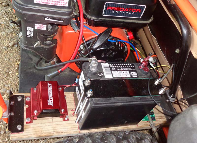
Figure 15. All the new parts mounted behind the seat next to the engine. Note coil wire and battery ground cable do not interfere with the starter pull mechanism.
The switch panel is 22 gauge sheet metal trimmed to match the angled opening below the steering wheel. It’s attached using six #12 machine screws with lock nuts. The switch wires are pull-tied to the throttle cable running under the seat (see Figure 2 again). At the rear of the seat is a Delphi automotive style connector to allow quick and easy removal.
From the connector, one wire is fused (three amp) to the battery; the other connects the switch to the controller’s red wire. The coil B+ wire is run through a five amp fuse directly to the battery (to keep the installation temporary).
The coil driver IGBT has a pull-down resistor preventing it from “floating” and causing unintended coil activation, so when the controller is powered down, the coil driver is off.
Just because I had it laying around, I ran a #4 battery cable from the battery negative to the engine block. I also ran ground to the chassis with 18 AWG wire. The magneto trigger wire is still connected to the stock kill switch, so both switches are functional. The basic wiring overview is outlined in Figure 16.
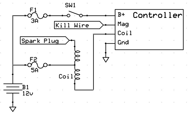
Figure 16. Simplified diagram showing installation wiring.
Emissions
I know there are several “green” minded folks reading this. Somewhere, somebody is thinking, “Okay, it adds performance, but what does it do to the pollution levels?” Well, I’m glad you asked! It just so happens that I have a rather high-end EMS Model 5003 5-gas emissions analyzer (that just came back from service and calibration) for my work (see Figure 17).
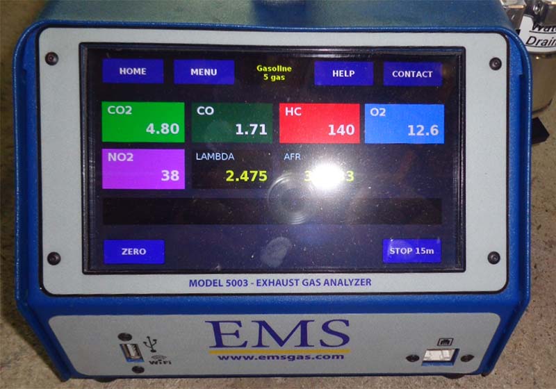
Figure 17. EMS 5003 5-gas emissions analyzer used for emissions testing.
I’m not able to measure the exhaust emissions on the go-kart at all load ranges while motoring around the lake, but I just happen to have a Honda 5 HP engine with modified exhaust for work-related testing (refer back to Figure 3). I was able to at least measure the no-load emissions on the Honda throughout the RPM range.
I’m glad I held off submitting this installment until I had it mostly finished because testing showed elevated HC and CO emissions over stock, regardless of timing. That was a clear indication of random misfires. I remembered how GM used ionic feedback to ensure the spark plug had done its job. If there was a misfire, the ECU would fire the coil a second time to at least mitigate emissions.
Adding the FC bit flag (Work.FC) in the PBP3 software functionality allowed the ISR Get_Tach: to monitor if the coil had been triggered since the last TDC, and fire it immediately if not. This brought emissions down even lower than stock and smoothed the engine out a bit. (Be sure to read the Emissions article and spreadsheet included in downloads.) It’s better to have a late spark than no spark.
Time to Test Thrash
With all the hardware mounted, wiring connected, and carb spacer modified and hosed, it was time to test our work. We started with the X-Y timing table numbers I dialed in on the Honda test engine.
Although the Predator is billed as a Honda knock-off, I couldn’t even get it to start with the Honda baseline. In fact, I had to advance the bottom timing cells by around 30 degrees to get it running!
The Nextion software from several articles ago limited advance to 40 degrees in the “+” button Touch Release Event software on the Tune screen (page 3). I uploaded a new version with the limit increased to 60 degrees (see the downloads). I also found that the Honda magneto produced two triggers per TDC, but the Predator only produced one. The timing of the events was different as well. In the PBP software in the downloads, there’s a choice of a Positive or Negative Edge trigger for INT in the INTCON Register. You may have to change that for your application. (One is commented out, but both have comments stating what they do.) Changing INT trigger polarity got the Predator timing numbers closer to the Honda versions.
To tune, initially just lightly breathe on the throttle and back off when the engine is around 2500 RPM. Adjust timing in the red-border highlighted cells (in either direction at first) by about two degrees per step to see if it responds better or worse. If better, take the timing in the same direction a little more. If worse, go the other direction.
The least amount of timing advance that still delivers full power is the best setting. Fine-tune with one degree steps. Move on to deeper and deeper throttle stabs, and higher and higher RPM ranges, filling in the cells as you go. This involves using your calibrated “butt dyno;” in other words, seat-of-the-pants “Does it feel better?” tuning.
The Verdict
Charles Leo has designed high-end automotive racing controllers (using PIC eight-bit MCUs programmed with PBP3) that go for big money, and wins races for his customers. He warned me early on that anticipating spark timing with only one pulse per revolution would probably not work as well as I expected. However, this project was inspired by two previous work projects; one which involved retarding ignition timing on a small engine to run it on hydrogen. The amount of time between a crank pulse and coil firing when retarding timing is relatively small, yielding no noticeable error.
The other project was a 1500 watt generator which had a 36-1 tooth crank trigger installed (and was also fuel injected). With a 36 pulses-per-revolution spacing (10 degree intervals), timing signals were as tight as they would be on an automobile. As Charles predicted, we couldn’t even match the overall performance of the stock magneto.
An additional victim of dynamically changing engine speed is the timing for reading the vacuum signal. I could see the Y axis (Load/Vacuum) jumping around radically as the engine would accelerate. At steady throttle, it ran great. Though we didn’t test scientifically, it appeared to require less throttle at any given steady speed and load. This is supported by the Honda testing, and suggests improved steady-state fuel efficiency. Applications like a lawn mower or generator could benefit from the controller as-is.
It might be possible to use the difference in RPM (and/or possibly vacuum) from one cycle to the next to better anticipate the next spark event (think PID). Another thought I had was to use an R/C pre-filter from the MPXA6115 vacuum sensor to give it a hint of lag, and feed that into a comparator’s inverting (-) input. The direct non-filtered vacuum signal would go to the non-inverting (+) comparator input.
When the vacuum signal changes direction, the comparator output will go high. This can be used as an input to an IOC (Interrupt On Change) pin on the PIC, causing an interrupt to trigger an ADC (analog-to-digital converter) read of vacuum, as opposed to the Timer 5 scheme (Suck:) currently used. (The PIC16F18426 has built-in comparators in its list of Peripherals.)


Figures 18-19. Enjoying the spoils!
Conclusion
This series of articles was geared towards learning about the Nextion touch screen firstly, and putting it to use in a real world project secondly. The ignition timing controller was chosen as an application illustration, as I had already succeeded twice before. I really hadn’t anticipated the few hick-ups this application created.
We did indeed drive the kart around the lake; did get improved exhaust emissions on the Honda test engine; and did get indicators suggesting improved fuel efficiency at steady-state load and RPM. The major glitch is with transients. I consider the project an overall success, and hope you find value as well. I may consider adding functionality (like the recommendations listed) and revisit it in a future article. NV
Parts List
- Vacuum Port Brass Tubing: McMaster-Carr PN 8859K18; Ultra-Formable 260 Brass, Round Tube, One Foot Long, 0.014” Wall Thickness, 3/32” OD.
- Vacuum Tubing: McMaster-Carr PN 5648K23; Polyurethane Tubing for Air and Water 3/32” ID, 5/32” OD, Opaque Blue, 25 ft Length.
- Clamping U-Bolt: McMaster-Carr PN 3042T144; 1/8” ID, Threaded 1/4”-20, Steel, 10-Pack.
- Ferrite Ring for RFI Suppression: Digi-Key PN 1934-1348-ND; 7.93 ID, 41 ohms.
- Toggle Switch: I used a RadioShack PN 275-324 I’ve had for years. Any SPST >3A switch should work.
- Ignition Coil: Speedmaster PCE382.1007, Jeg’s PN 746-PCE382.1007; 100:1 Turns Ratio, E-core.
- Taylor Solid Core 8 mm Ignition Wire: Jeg’s PN 895-35281; 30’, TCW Wire Core, Red.
- Taylor 90 Degree Spark Plug Boot & Terminal Kit: Jeg’s PN 895-46001; Silicon, Black, Four-pack.
- Small Plastic Pull Ties (available in auto parts and hardware stores).
- JB Weld Two-part Epoxy (available in auto parts and hardware stores).
- Various Pieces of Strap Steel, Angle Iron, 3/8” Stainless Lag Bolts, 1/4” x 20 Threaded Rod, 1/4” x 20 Lock Nuts, Paint, etc. (for fabricating mounting brackets and battery hold-down).
- #4 Wire & Eyelet Terminal for Ground Wire (battery to engine; anything #16 or larger should work).
- Two Fuse Holders (I had laying around), 3A and 5A Fuses.
Downloads
What’s In The Zip?
Emissions Article
Emissions Spreadsheet
PBP Software