If you’ve been reading Nuts & Volts for a while, you’ve most likely heard of the Parallax Propeller chip. If you haven’t heard of it, you’ve been missing out! In this article, we’re going to look at the Propeller FLiP board. This board packs all the power of the Propeller chip into an easy-to-use breadboard-able form factor. It’s ideal for experimentation and inclusion into your projects. Who knows, it may even become your favorite board!
The Propeller has many programming languages available, but in this article, we’ll be using a graphical programming language called BlocklyProp. This is a Visual Programming Language (VPL) based on Google’s Blockly open-source engine, and there’s a whole generation of young people coming up who’ve learned to program this way.
BlocklyProp is very easy to use and therefore ideal for beginners, but it packs a surprising amount of power. We’ll start off with the mandatory Blink example to get everything set up; add some parallel processing goodness to that to demonstrate the unique parallel processing features of the Propeller chip; and finally, we’ll end up with a simple — but very useable — binaural beats mind machine. However, before we get into all this, we should look at what makes the Propeller chip so special.
Propeller = Parallel Processing Power
The big thing about the Propeller chip is that it has eight identical cores. Each of these is a 32-bit powerhouse that can run at up to 80 MHz. Multiple cores make the Propeller the ideal solution for any project where you need the microcontroller to do more than one thing at a time.
With a single core, you have to simulate parallel processing using timers and interrupts, but with the Propeller, you get the real thing — eight independent cores. The cores all operate in parallel, and you can assign different tasks to different cores to get the job done simply and efficiently.
This is obviously fantastic for robotics applications, but it can also make many other types of projects a lot easier. It’s a bit like setting out with eight Arduinos (or other boards) that can all work together seamlessly. It’s fair to say that parallel processing has usually been considered quite an abstruse art, but the Propeller chip — because of its unique architecture — makes it easy. We’ll look at this next.
Propeller Architecture
A simplified schematic of the Propeller chip is shown in Figure 1.
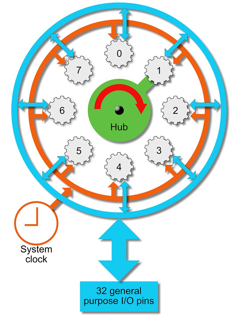
FIGURE 1. Simplified Propeller architecture.
As mentioned, there are eight identical 32-bit cores that we’ll refer to as processors (also known as “cogs” in some of the Propeller documentation) that can run at speeds up to 20 MIPs. Each processor has its own 512 x 32 bits of working memory, two counters, and a video generator. As well as the processors, there’s a central hub that coordinates them, and contains shared resources comprising 8192 x 32 bits of RAM and the same amount of ROM. You can find out all about the Propeller chip in the comprehensive datasheet listed in the Resources section.
The processors run in parallel, synchronized by the system clock, and the hub cycles sequentially through them, offering each one sole access to the hub resources in turn for one clock cycle. In fact, this is the reason the chip is called the “Propeller” — the hub effectively “rotates,” servicing each processor sequentially.
Processors can use the hub RAM to exchange information in a safe way because only one processor has read/write access to it on any cycle. This approach removes most of the resource contention issues that can plague parallel processing and allows Propeller programs to be simple and robust.
Should a processor need more than a single clock tick to access hub memory (say to access elements of an array), there are lock bits available that can lock a memory block for exclusive access, so you can take control of resource management if you need to. Mostly, you don’t.
The Propeller (and especially the FLiP) makes a lot of things simpler. For example, apart from the inevitable power and reset, there are no special purpose pins. This is actually quite a big deal. If you consider the pinout of a typical board such as the Arduino Uno, it can be somewhat daunting because each pin can have several functions, and different groups of pins are assigned different groups of functions.
With the Propeller, a pin is just a pin and its behavior is determined by the software that you connect to it. This makes it very easy to design breadboard layouts and printed circuit boards (PCBs). It’s also immensely flexible!
If you need a lot of Tx pins for serial communications, you can have them! Need lots of PWM pins for servos? No problem! Just connect the appropriate software to your choice of pin to give it the functionality you want. This is an idea referred to in the Propeller documentation as “software peripherals,” and it’s a very powerful idea indeed.
You might wonder how the processors interact with the pins given that the processors run in parallel. Again, it’s simple. Any processor can set the direction of any pin and use it as an input and/or output as it chooses.
The issue of contention between processors for the same pin is resolved in an elegant way by three rules:
- A pin is an input only if no active processor sets it to an output.
- A pin outputs low only if all active processors that set it to output also set it low.
- A pin outputs high if any active processor sets it to an output and also sets it high.
I could say a lot more about the Propeller chip (in fact, there have been several books written about it; see the Resources section), but this is a practical article. So, let’s get going using it with the FLiP board!
The FLiP Board
Figure 2 shows a photo of the FLiP board and Table 1 gives you a summary of its specifications.
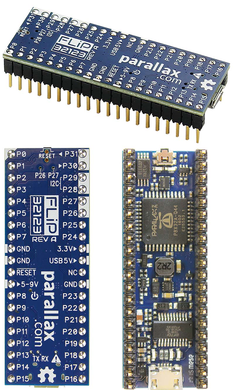
FIGURE 2. Some views of the FLiP board.
| Microcontroller |
Eight-core Propeller P8X32A-Q44. |
| EEPROM |
64 KB on I2C. |
| Oscillator |
5 MHz SMT. |
| Form Factor |
40-pin DIP with 0.1” pin spacing. |
| GPIO |
32 accessible, 26 fully free:
P26 & P27: User-programmable LEDs.
P28 & P29: I2C bus with EEPROM.
P30 & P31: Propeller programming. |
| Power Input |
5V via USB, or 5-9 VDC via VIN pin. |
| USB Protection |
USB limiter and fault loop circuit. |
| 3.3V Protection |
Switching supply short-circuit and over-current protection.
Reverse-current protection on 3.3V output pin. |
| Current Limits |
400 mA from USB port, via 3.3V, 5V, and I/O pins.
1,500 mA from USB supply, via 3.3V, 5V, and I/O pins.
1,800 mA from 5-9V pin, via 3.3V and I/O pins. |
| Communication |
Serial over micro USB. |
| Operating Temperature |
-4 to +185 °F (-20 to +85 °C). |
| PCB Dimensions |
~ 2.0 x 0.7 in (51 x 18 mm). |
TABLE 1. FLiP board specifications.
The board is a joy to use because all the components are tucked away on the underside, and the top surface is very clearly marked with the pinout as you can see in the figure. A few LEDs peep through little holes in the board. The micro USB programming port is at the bottom, and the RESET pushbutton under the top edge.
The FLiP is a 3.3V board that can be powered from the USB port or externally via the pin labelled 5-9V. Because logic 1 is at the 3.3V rail and logic 0 is half of that, it can drive 5V logic just fine. It can also accept 5V on any input pin via a series resistor somewhere between 3.9K (minimum) to about 10K (recommended).
For simplicity, I do not mix 3.3V and 5V logic unless I really have to. All inputs are floating, so a 10K pull-down resistor to GND should be used when interfacing with switches or anything that can be open circuit. Apart from that, you can use it much like any other board. It has no built-in analog-to-digital or digital-to-analog converters (ADC and DAC, respectively), but these can be easily implemented as software peripherals plus a few external resistors and capacitors.
If you look at Figure 2, you can see that the FLiP has 32 general-purpose I/O pins. These are very conveniently organized into four groups of eight, numbered counterclockwise from the top left: P0 to P7; P8 to P15; P16 to P23; and P24 to P31. Although each Propeller I/O pin is identical and completely general-purpose, the FLiP board attaches some resistors and/or LEDs to six of them, which changes their electrical properties as follows:
- P26, P27 — user LEDs (equivalent to 65K pull-down resistors).
- P28, P20 — I2C with 3.9K pull-up resistors to 3.3V.
- P30, P31 — Propeller programming pins with 10K pull-up resistors to 3.3V.
You can still use P26 to P31 provided you are aware of their existing electrical connections. To keep things simple, avoid them unless you really need all the pins.
Each pin can source up to 400 mA up to a total for the board of 1,500 mA (when powered through the USB connector) or 1,800 mA (when powered through an external power supply). This is similar to other boards, and quite sufficient for most purposes.
The FLiP plugs into your PC or Mac via a micro USB cable, and can be programmed in several languages as mentioned previously: Spin (my favorite!); C; Propeller Assembly; and BlocklyProp. There are development environments available for all these languages on the Parallax site (see Resources), and I intend to look at some of these — particularly Spin. However, to get started, we’ll go with the graphical BlocklyProp language because it’s very simple to set up and use; provides a great way to demonstrate parallel processing on the Propeller chip; and is fun!
Getting Started with BlocklyProp
To get set up for development in BlocklyProp, go to the website at https://blockly.parallax.com/blockly. The landing page is shown in Figure 3,
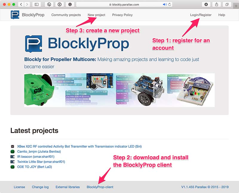
FIGURE 3. The BlocklyProp home page.
and there are three steps to get going:
- Register for an account. This will give you access to the BlocklyProp development environment and a place where you can store your projects online.
- Download and install the BlocklyProp client. Because BlocklyProp is an online tool that runs in your browser, it needs the client to communicate with the FLiP and other boards. If you don’t have the client running, then nothing will work, and you’ll get error messages!
- Create a new project.
Setup is very simple, but if you have any trouble or just want more detailed instructions, there is excellent online help that will walk you through the whole process at http://learn.parallax.com/tutorials/language/blocklyprop/getting-started-blocklyprop.
The source code for all the projects discussed here is hosted online at the BlocklyProp site (see Resources).
Blink!
I think it’s a tradition or an old charter or something that every development board must be introduced with a version of the Blink program. It appears to be the “Hello World” of the maker community and is as good a place to start as any. So, that’s what we’ll do here.
We’ll use the multiprocessing powerhouse that is the Propeller chip to blink an LED! Welcome to the 21st Century! However, we won’t stop there ...
The first thing to do is to set up a test circuit. You might as well set up the circuit shown in Figure 4. It has four LEDs, but we’ll only use one of these for now.
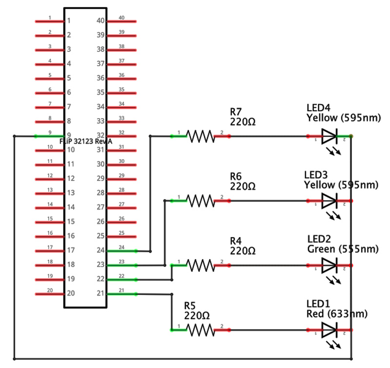
FIGURE 4A. The circuit for Blink and Blinkenlights.
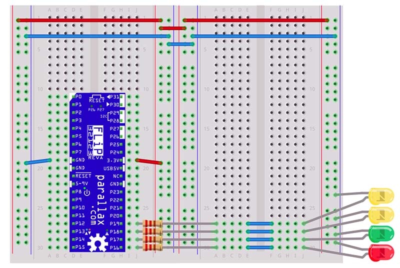
FIGURE 4B.
Be careful when wiring up the power lines to get the positive and negative rails connected correctly. The FLiP is quite robust and will probably survive a short, but it will not thank you for it! The four LEDs have their cathodes connected to ground (the short pin next to the flat on the package) and their anodes to FLiP pins P16, P17, P18, and P19 via 220R current-limiting resistors. The LED colors are not critical.
Let’s write Blink! First, perform the following steps:
- Plug your FLiP into a USB port.
- Start the BlocklyProp client app (Figure 5).
- In the app, click on “Connect” to connect to your FLiP.
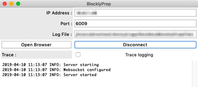
FIGURE 5. The BlocklyProp client.
If you have connected correctly, you should see something like Figure 6.
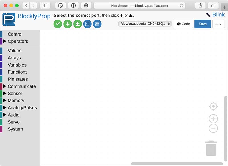
FIGURE 6. The BlocklyProp development environment.
In the client, click on “Open Browser” to go to the BlocklyProp site. Log on, and create a new project called Blink. When you create the project, be sure to set the “Board/Device type” to “Propeller FLiP or Project Board.” This is important!
There are several Propeller boards and you need to select the right one. You can also set the visibility to “Unlisted” if you want to keep it private, or to “Public” if you want to share it. You can change these settings later. Again, your new project will look something like Figure 6. There’s a blank canvas in the middle of the window; down the left-hand side is a list of block categories; and along the top are some controls that we’ll discuss shortly.
The BlocklyProp programming paradigm is all about connecting up blocks that represent code. If you click on any of the block categories down the left-hand side of the screen, you will see the blocks available in that category.
Try opening a few categories to see what’s there and drag a few blocks on to the canvas. If you right-click on a block, you’ll get a context menu with the following options:
- Duplicate - Lets you create a duplicate of a block. This can be a real time saver. Rather than having to go back into the categories to find a particular type of block, you can create a copy of an existing one.
- Collapse Block - Useful if you have a lot of blocks in a stack.
- Disable Block - Important for debugging. You can Enable and Disable blocks to see the effect they have on your program.
- Delete Block - Does exactly what it says.
- Help - Takes you to the documentation for the block in the excellent and comprehensive BlocklyProp help system. I suggest you take a little time to familiarize yourself with this.
Let’s move on now. Delete any blocks you’ve added so that you have a clean canvas.
We want our Blink program to flash the LED on pin P16. To do this, we require a loop. Inside the loop, we’ll make P16 high, wait for one second, make it low, and wait for one second again. This will give a symmetric square wave output that will blink the LED.
Connect the blocks up as follows:
- Go into the Control category and drag the add block on to the canvas. Enter a comment in the slot provided. It’s always a good idea to begin with a comment!
- Go into the Control category again and drag out the repeat forever block (which is an infinite loop) and connect it to the bottom of the add block. It should click into place.
- Go into the Pin states category and drag the make PIN block into the body of the loop. Again, it should click into place. Set the first slot to 16, and the second slot high.
- Go into the Control category and drag the pause (ms) block under the make PIN block. This defaults to a 1,000 ms delay. Set it to 500 ms so we get a 1 Hz flash.
- As you might expect, we now need to add another make PIN block under the pause (ms) block — still on pin 16 — but this time set to low.
- Add a final pause (ms) block under the last make PIN, set it to 500 ms, and that’s it!
Your program should look exactly like Figure 7.
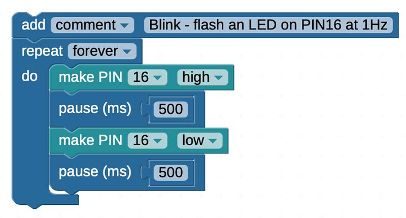
FIGURE 7. The Blink BlocklyProp program.
If it doesn’t, add and delete blocks until it does. Make sure you have no floating, unconnected, or extra blocks hidden under any of the others.
Now we are ready to check the program!
At the top of the BlocklyProp screen is a row of three buttons: three green and two blue. The green tick button is used to check your code; it compiles it without downloading it to a board. Click it now. You should find that everything is okay, and you get the message, “Compile... Succeeded.”
If there’s an error, check that your stack of blocks looks exactly like Figure 7; check that all the blocks have clicked into place; check that there are no rogue unconnected blocks floating around or hidden under other blocks; and check that the BlocklyProp client is running and connected.
BlocklyProp is a code generator, and if you click on the Code button (top left next to Save; it has an eye on it), you can see the C code that is generated and compiled. Examining the generated code is a great way to learn how to use C with the FLiP!
The compiled code must now be downloaded to the FLiP. Click on the green down arrow button to load the code into processor 0 RAM. Watch the blue receive LED next to pin 13 flash as the code is loaded onto the board. You should then see the LED you connected to P16 flashing once per second. That’s your first BlocklyProp program!
At this point, we need to stop and take stock of what is going on. You need to know that the Propeller chip uses three types of memory:
- ROM that holds system-specific information.
- RAM that can be used to hold program data and transient programs.
- EEPROM that can be used to hold persistent programs (and data if you want).
BlocklyProp lets you download the compiled code into RAM (green arrow) or EEPROM (green arrow on baseline). If you load the program into RAM, it downloads very quickly, but the program will be lost if the FLiP is reset or if the power is cycled. This mode is perfect for playing around with the FLiP and developing programs. It’s the mode you will use most often, and it’s what we’ll use here.
When you download the code into EEPROM, it takes a bit longer to download, but the program is persistent, and will simply re-run on a reset or power cycle (similar to an Arduino board). Typically, in development, always load to RAM until the code is finalized, then you can load the finished version to EEPROM.
In terms of the speed of execution of the program (as opposed to speed of download), it doesn’t matter where programs are loaded to because programs always run from RAM. This is an important point!
Any code loaded to EEPROM is always copied to working RAM before it’s executed. By default, code is loaded into processor 0. We’ll see how to run code in the other processors shortly.
Annotated Blink
Having got the Blink program working, we are now going to modify it so that it sends information back to the BlocklyProp Terminal. This is an important debugging technique that you need to know right now.
Go into the Communicate category and place two Terminal print text blocks one above each of the pause (ms) blocks. As you might expect, these blocks allow you to print text back to the BlocklyProp Terminal. Change the first block to say “LED On” and the second block to say “LED Off.” Make sure the check box is checked so that there’s a new line after every print. Your program should look like Figure 8.
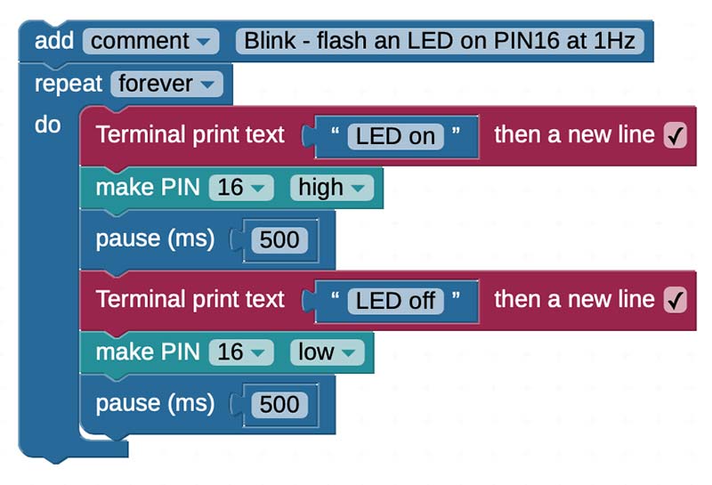
FIGURE 8. Blink with annotations to the Terminal.
Run the program. The BlocklyProp Terminal should open, and you will see the messages “LED On” and “LED Off” being printed out from your program as the LED turns on and off. If you look at the FLiP carefully, you’ll notice the red transmit LED close to P13 flash every time a message is sent. All this code is being run in a single core, and the communication with the Terminal takes a small but finite amount of time. The output frequency of the program will now be slightly less than 1 Hz.
All this is fine, but we are still only utilizing a single core of the Propeller. We have seven more to use! In the next section, we’ll see how to do this.
From Blink to Blinkenlights
As I’m sure most of you know, Blinkenlights is a hacker term for the flashing lights commonly found on old computer (and other) equipment. Ancient hackers (such as myself) still pine for them, and miss passing the idle hours basking in their comforting, hypnotic glow! In this section, we’ll develop some Blinkenlights to illustrate the ease, power, and fun of multi-core programming.
If you set up the breadboard as I suggested earlier, you will already have four LEDs connected via 220R resistors to FLiP pins P16, P17, P18, and P19. If you don’t, then please connect them up now. We are going to drive each of these LEDs from their own processor at a different frequency.
The most basic recipe for multi-core programming in BlocklyProp is as follows:
- Create a function block for each task you want to execute in parallel (category Functions).
- Launch a processor for each of these function blocks using the new processor block (category Control).
That’s it! The main program that does the launching comprises a set of new processor blocks and runs (by default) in processor 0. Every call to new processor launches the supplied function block in another processor.
I don’t think multi-core programming can get much easier than this. Let’s create a multi-core Blinkenlights program. First, create a new program as before. Next:
- Create four function blocks called blink16, blink17, blink18, and blink19 as shown in Figure 9. The function blocks are found in the Functions category.
- In each function block, add a frequency PIN block with the values shown in Figure 9. These blocks output a square wave of the specified frequency on the specified pin. They live in the Audio category/sub-category Frequency out.
- Create three new processor blocks and join them together as shown (in fact, you don’t need to join them in this case, but it’s neater). These live in the Control category.
- Finally, go back into the Functions category. Automagically, you should now find run function blocks for each of your functions — blink16, blink17, blink18, and blink19 — that you defined in step 1. Drag these blocks inside the new processor blocks as shown.
If you check the program then download it to RAM, the four LEDs should all start flashing at different frequencies. Try doing that on an Arduino! If not, check your wiring, and check that your program looks exactly like Figure 9.
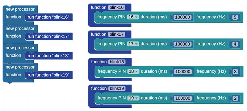
FIGURE 9. Blinkenlights BlocklyProp code.
So, what’s going on? The top-level program is the sequence of new processor blocks on the left-hand side of Figure 9. These execute sequentially top to bottom — as you might expect — in processor 0. Each new processor block launches its function in a new processor. This means that the functions blink16, blink17, blink18, and blink19 all run independently and in parallel, and output their frequencies (5, 4, 3, and 2 Hz) on the specified pins.
Each processor needs its own working memory, and new processor allocates 128 bytes of stack space for each processor. This is generally adequate, but you should be aware of the limitation. Other Propeller languages give you precise control over stack space allocation, but BlocklyProp just defaults to 128 bytes for each processor.
It’s also worth pointing out that BlocklyProp tries to keep things very simple, and doesn’t give you much control over killing processors and returning them to the pool for reuse. As such, once you have assigned a processor with new processor, that’s it. You won’t get that processor back to do something else. Other Propeller languages don’t have this restriction.
Well, having constructed the pretty (but somewhat useless) Blinkenlights program, let’s turn it into a working mind machine! In terms of hardware, we are almost there.
From Blinkenlights to Binaural Beats
WARNING: Do not use mind machines if you suffer from any kind of epilepsy or seizures. Do not use mind machines or listen to binaural beats while driving or operating machinery. If you experience any unusual sensations, stop using the machine immediately!
Binaural beats occur when two different tones are played into each ear using stereo headphones. If the tones are just a few Hz apart, the brain synthesizes a beat frequency that is the difference of the two input frequencies. So, if one tone is, say, 260 Hz (about middle C) and the other tone is 264 Hz, you will hear the blend of both tones plus a 4 Hz beat frequency that is not present in either ear, but is synthesized directly by your brain.
The beat frequencies are often below the threshold of hearing, and you experience this as a pleasant pulsing of the tone. I enjoy using binaural beats, and find they work quite well for me. With this simple mind machine we’re going to create now, you’ll get a chance to experience them for yourself.
There is quite a lot of good evidence that binaural beats can give rise to a phenomenon known as brainwave entrainment, in which your brainwaves tend to come into synchronization with the beat frequency. This is known as the frequency following response. Different brainwave frequencies are associated (somewhat loosely) with different mental states, so by selecting the right binaural beat frequency, you may be able to entrain states such as relaxation, creativity, or concentration.
Brainwave frequencies are listed in Table 2, along with mental states they may possibly entrain.
| Name |
Range |
Possible Effects |
| Gamma (G) |
100 Hz to 30 Hz |
Processornitive enhancement, memory improvement, problem solving. |
| Beta (B) |
30 Hz to 14 Hz |
External focus, analytical thinking, energy. |
| Alpha (A) |
14 Hz to 8 Hz |
Relaxed attention, stress release, positive thinking, flow states. |
| Alpha (S) |
7.8 Hz |
A special alpha frequency that corresponds to the Schumann resonance. |
| Theta (T) |
8 Hz to 4 Hz |
REM sleep, relaxation, meditation, creativity, hypnagogic states, dreams. |
| Delta (D) |
4 Hz to 0.5 Hz |
Deep dreamless sleep, pain relief (mind awake, body asleep), awareness of normally unconscious processes. |
TABLE 2. Brainwave frequencies
Of course, achieving successful entrainment and its associated mental state can depend as strongly on set (short for your mindset) and setting (your physical and social environment) as on technology. If, for example, you want to relax, you first have to put yourself in a situation where relaxation is possible. This is essential, and no known mind machine technology can do that part of it for you!
Generally speaking, entrainment seems to work quite reliably from high alpha down to high delta; anything else can be a bit hit and miss and requires practice. A frequency that I find particularly pleasant is the Schumann resonance at 7.83 Hz. This is the fundamental resonant frequency of the Earth’s electromagnetic field between the surface of the Earth and the ionosphere, and it lies right on the theta/delta boundary. Perhaps it’s the stuff dreams are made of! You can build the BlocklyProp mind machine by adding a 3.5 mm breadboard mounting jack socket and two10K potentiometers to the existing Blink circuit as shown in Figure 10.
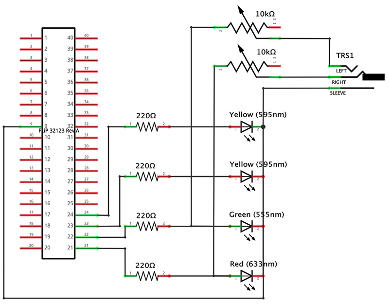
FIGURE 10A. The binaural beats mind machine circuit.
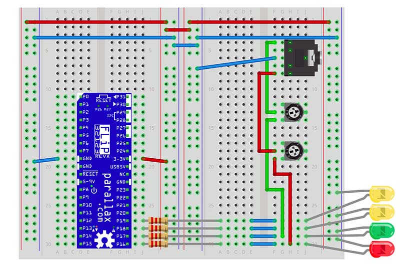
FIGURE 10B.
To keep the circuit as simple as possible, there is no separate amplifier. We drive the headphones from the 220R resistors connected to the FLiP’s P16 and P17 and use the 10K pots as volume controls. This seems to work okay, but given that this is a rather sharp square wave, I would not advise using this simple circuit with your best headphones! In fact, you don’t need great fidelity for binaural beats, and cheap headphones will work just fine.
Whenever you’re working with headphone circuits, safety is important:
- Start with the volume turned down to the minimum, then slowly turn it up.
- Always check the volume by holding the speakers close to — but not in — your ears.
- Only put the headphones on when you’re sure the volume level is set to a comfortable level!
As you can see, the hardware is quite trivial. The software is where the multi-core magic happens, and we’ll look at that next.
Binaural Beats Software
Now that you have the hardware in place, the next thing to consider is the software. The mind machine has to entrain the user’s brainwave frequencies using the frequency following response. This means that it should start at a frequency in the range of normal conscious awareness (alpha/beta); allow the brain some time to synchronize; and then lower (or raise) the frequency slowly over time to reach the target frequency.
The frequency change needs to happen at such a rate that the brain has a reasonable chance to respond. If you were to try to go straight from normal beta/alpha directly to delta, for example, that is unlikely to work well.
For this reason, most mind machines (and ours is no exception!) run sessions that vary the brainwave frequency over time. These sessions generally start somewhere in the beta/alpha range (close to waking consciousness) and descend/ascend to the target frequency over a period of some minutes, allowing the brainwaves some chance to become entrained.
After holding in the target frequency for a period of time, a session may either return back to beta/alpha or just terminate. Typically, a session for relaxation and mediation will ramp back up to beta/alpha to encourage a return to the normal waking state, while sleep sessions will end in the target state — theta or delta.
We’re going to define our session as a sequence of segments, where each segment is a target brainwave frequency held for a particular duration. This means that rather than a continuous change in frequency, the sessions will change in steps. This is not necessarily a disadvantage because achieving a particular mental state is often as much down to set and setting, and having an audible signal that a frequency has changed can be a psychologically useful cue.
I have provided you with four sample sessions described in Table 3.
| Program |
Segments (each held for 5 mins) |
Effect |
| Relaxation |
A,S,A,S,A,S |
Relaxing alpha frequencies for 30 mins. |
| Meditation |
A,S,T,T,T,A |
Descent from alpha (5 mins) through Schumann resonance (5 mins) into the theta target state (15 mins). Back to alpha (5 mins). This should be good for dreamy meditative kinds of states. |
| Sleep |
A,T,D,D,D,D |
Descent from alpha (5 mins) through theta (5 mins) into the target delta state (20 mins). Leaves you in delta. Should be good for sleep induction. |
TABLE 3. Mind machine sessions.
After walking through the software, it should be very easy for you to add to this list by creating your own.
There is also a test session that is not shown in the table. This descends rapidly through the sequence G,B,A,S,T,D spending five seconds at each frequency. It’s useful for debugging because you only have to wait five seconds for something to happen.
The BlocklyProp software for the mind machine is a bit more complex than anything we’ve seen up to now, but there is really not much that is new. The main program is shown in Figure 11.
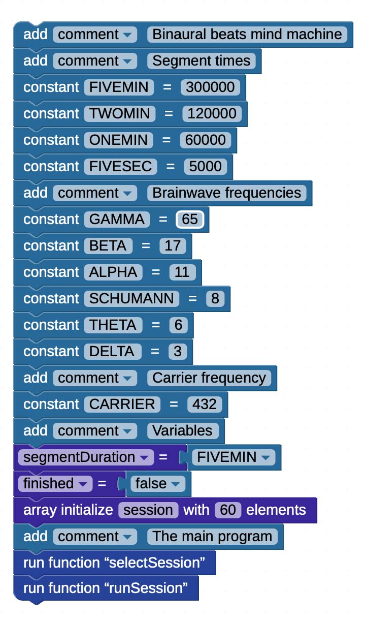
FIGURE 11. The binaural beats mind machine main program.
This starts with a lot of constant definitions (we’ll see what all of these do shortly); an integer variable, segmentDuration (guess what that does!); a Boolean variable, finished; and the integer array session that contains slots to hold the frequencies comprising a particular session. We’ll only use the first six slots for our sessions here, but I’ve left plenty of space for longer or more granular sessions if you want.
After the constants and variables, we go into the main program. We first execute the selectSession function, then the runSession function. Remember that this main program is running in processor 0.
Figure 12 shows the selectSession and runSession functions, and the relaxation function that defines the brainwave frequencies for the relaxation session. The selectSession function provides a simple user interface based on the Terminal that allows you to select one of the three built-in binaural beats sessions described back in Table 2. You enter a number between 1 and 4 to select the session you want, and it executes the function corresponding to the selected session to set things up.
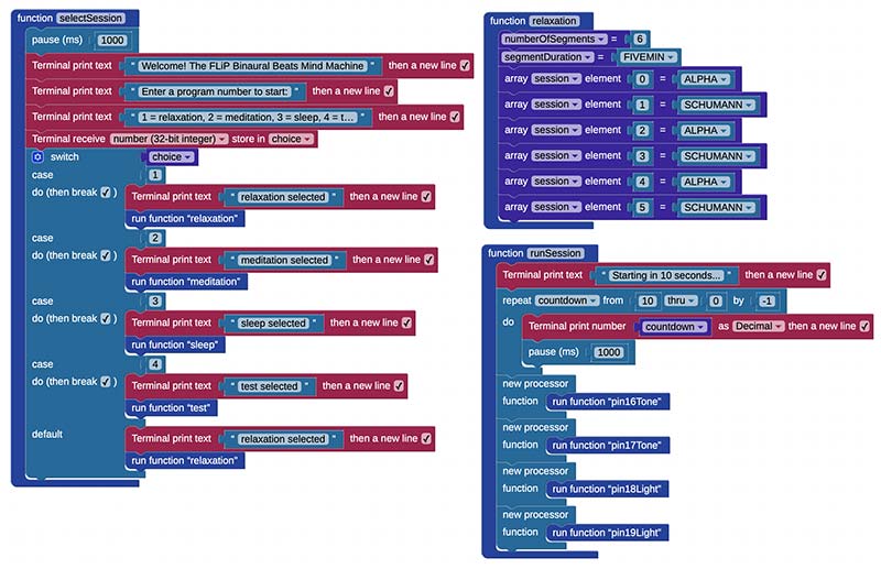
FIGURE 12. The selectSession, relaxation, and runSession functions.
For example, if we select 1, this executes the relaxation function (see Figure 12). There is one function per session, so we also have meditation, sleep, and test functions. These session functions are very simple. They set the numberOfSegments (6), the segmentDuration (5 mins), and put the appropriate frequencies in the session array. Each one sets up a particular binaural beats session ready to execute.
One interesting thing to point out is that the switch block has a little symbol that looks a bit like a gear right at the top. This is the mutator for the block. Some blocks (such as switch), have an internal structure — also made up of blocks — that can be edited. If you click on the symbol, you’ll see a pop-up editor that allows you to add more cases.
The fun starts in the runSession function. As you can see from Figure 12, this block starts by giving you a 10 second countdown.
This should be enough time to get your headphones on and get comfortable.
It then launches four processors, using new processor blocks as we saw earlier. These run the output functions pin16Tone, pin17Tone, pin18Light, and pin19Light in parallel. These functions are shown in Figure 13.
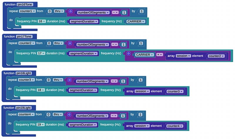
FIGURE 13. The output functions for tones and lights.
The binaural beats are generated by a carrier tone on P16 that is generated by the pin16Tone function, and a tone that is a carrier + brainwave frequency on P17 generated by the pin17Tone function. If you look at these two functions in Figure 13, you can see that they output a particular frequency for a time determined by segmentDuration for each segment in the session. The carrier function pin16Tone always outputs the same frequency, which we have set (somewhat arbitrarily) to 232 Hz.
Generally speaking, carrier tones in this octave work well but you can easily change the value of the CARRIER constant to change the pitch. The function pin17Tone steps through the session array and adds each brainwave frequency to the carrier and outputs that.
The functions pin18Light and pin19Light step through the session array and output the brainwave frequencies on P18 and P19, respectively. If you wanted to create a fully-fledged light and sound machine, you could use these outputs to drive lightframes (glasses with LEDs in them), but this is beyond the scope of this article.
The BinauralBeats program as it stands is a one shot: You run it, it runs the session, and then it terminates. We’re using the Terminal for our interface, so the FLiP is connected to the host computer at all times. So, it’s no problem to download the program into RAM and run it when you need.
That’s it! You now have a working binaural beats machine. I hope you enjoy it and find it interesting and useful.
Summary
Hopefully, this article has given you the “multi-core bug” and that you’ll see how you can use the Propeller chip — and in particular the FLiP boards — in your future projects. We have only really scratched the surface of what these boards and BlocklyProp are capable of, and even more is possible using other Propeller languages such as Spin and C.
The message I hope you take away from this is that multi-core is easy and fun. I believe it’s the future! If you’ve enjoyed this article, please let us know. We’ll be sure to do some more Propeller stuff! NV
BlocklyProp Programming Guidelines
You can do an awful lot with BlocklyProp, and if it has a block that does what you need it to, then it may well be all you need. However, it is subject to some limitations:
- Integer arithmetic only. Yes — that’s right — and for some projects that might seem like a showstopper. Mind you, there was a time in the 1970s when most home computers only had integer arithmetic. With a bit of creativity, you can work around this.
- All constants and variables are global. When you define a constant or variable, it’s available anywhere in the program, to any processor, for read and write. You have to manage these globals very, very carefully indeed. For example, a common problem is to try to reuse the same variable (for example, an integer called “i”) as a loop counter in different processors. It doesn’t work because all variables have global scope.
- Functions don’t accept arguments and neither do they return values. Data can only be passed in and out of functions in global variables. In fact, if you’re a programmer, it’s best not to think of these as functions at all. They’re really just named stacks of blocks.
- BlocklyProp is a great way to learn Propeller C, but because of the global variable/constant feature, it doesn’t always generate the best code.
- Some blocks can only be used by the top-level processor. In particular, the Terminal ... blocks have this restriction. If your program isn’t doing what you expect it to, check in the Help section that you are not calling a block from the wrong level!
- Visual programming is verbose! What might take a few lines of code might need several rather large blocks, so your canvas quickly fills up. Collapse blocks to help with this.
- Not much control over processors. You can start a processor and er ... that’s it! This means that you can’t reuse processors in the same way you would in other Propeller languages. You can work around this, but it adds a level of complexity to the code. In particular, beware of loops that launch processors. If you launch too many, the application will just stop working without warning. I have it on good authority that this may be improved later this year.
- There is a User defined code block in the System category that lets you create your own blocks written in C. This requires you to have knowledge of Propeller C programming, and it’s also somewhat limited in what external libraries it can access. However, it can be a lifeline if there isn’t a block that does what you want. See Help for more information.
BlocklyProp is not a toy. It’s already being used in substantial commercial applications. Provided you are aware of its limitations, it’s a productive development environment. And it’s great fun!
Parts List
1 - Parallax Propeller FLiP microcontroller module (Parallax Product ID: 32123)
4 - 220R Resistors
2 - Half-size solderless breadboards
2 - 10K Breadboard trim potentiometers (Adafruit Product ID: 356)
1 - Audio jack 3.5 mm, PCB mounting (SparkFun Product ID: PRT-08032)
Resources
Documentation
Propeller FLiP board home page
https://www.parallax.com/product/32123
Propeller FLiP board datasheet
https://www.parallax.com/sites/default/files/downloads/32123-Propeller-FLiP-Module-Guide-v1.1.pdf
BlocklyProp home page
https://blockly.parallax.com/blockly
BlocklyProp reference
http://learn.parallax.com/support/reference/propeller-blocklyprop-block-reference
Propeller chip datasheet
https://www.parallax.com/sites/default/files/downloads/P8X32A-Propeller-Datasheet-v1.4.0_0.pdf
Source Code
BlocklyProp Blink code
https://blockly.parallax.com/blockly/projectlink?id=97282&key=22ac24ea-1080-4770-b483-927f36170094
BlocklyProp annotated Blink code
https://blockly.parallax.com/blockly/projectlink?id=97285&key=721deaab-f5e4-48f5-82ab-5b8853bc4ec4
BlocklyProp Blinkenlights code
https://blockly.parallax.com/blockly/projectlink?id=97289&key=d0baed91-e83d-47ae-9853-47e958b07521
BlocklyProp binaural beats mind machine code
https://blockly.parallax.com/blockly/editor/blocklyc.jsp?project=95675
Fritzing
Blinkenlights Fritzing
http://fritzing.org/projects/blinkenlights
Binaural beats mind machine Fritzing
http://fritzing.org/projects/propeller-binaural-beats-mind-machine
Books
“Programming and Customizing the Multicore Propeller Microcontroller: The Official Guide,” Parallax, McGraw-Hill/Tab Electronics (13 Jan. 2010), ISBN-13: 978-0071664509.
This is the definitive guide to the Propeller chip. Excellent, but now a bit out-of-date. There are several other Propeller books available, but this is the one I recommend.