The Raspberry Pi Zero has turned into a really different experience for me (I’m accustomed to using the PICAXE and BASIC Stamp). After a month, I’ve written complete flight code and even designed a camera system for the Pi. So, this month, I’ll fill you in on how I got the Raspberry Pi flight computer to where I can start planning to build an airframe. Next stop, near space!
Nearly Flight Ready
I’ve finally incorporated the following items into the RaspPi Zero flight computer: a Geiger counter to measure cosmic rays; a weather station to measure air temperature, pressure, and relative humidity; a GPS to measure time, 3D location, speed, and heading; and a digital camera. That’s everything I need for a really neat near space mission. Plus, plenty of room remains on the flight computer for the additional experiments that I’ll dream up later.
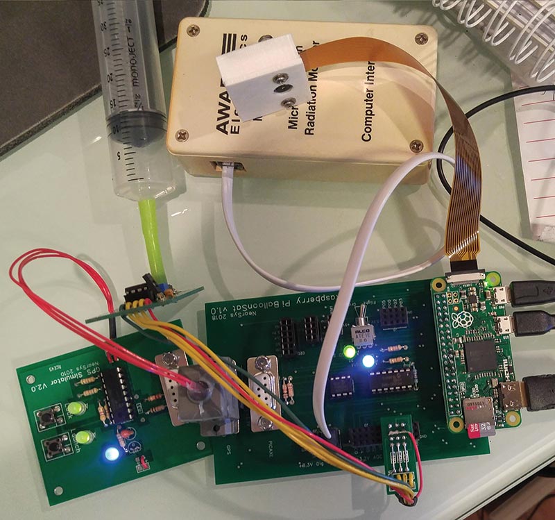
To test the Raspberry Pi Zero near space flight computer on the ground, I needed to do two things. First, I had to spoof it with a GPS simulator. The circuit on the left generates the GPS data typically seen during a balloon ascent. Second, the weather station needed a syringe, so I could pull a vacuum to simulate the air pressure changes found during a balloon ascent.
Geiger Counter and Weather Data
The PICAXE on board the RaspPi flight computer collects sensor data using its built-in ADC (analog-to-digital converter). Afterwards, it stores that data into the shared EEPROM for the Pi to read when it’s ready.
The PICAXE uses the BASIC code shown next to digitize sensor voltages with 10 bits of resolution and to store the results into the shared EEPROM. Note that pin C.3 connects the Pi to the PICAXE and is used to signal the PICAXE to stop updating the EEPROM while the Pi reads its stored data.
i2cslave 100000,i2cfast,i2cword    ‘ memory speed: 400 kHz, 1 word records<br />
  pause 1000
ADC:<br />
  if pinC.3 = 0 then goto ADC    ‘ wait until RPi is not reading EEPROM<br />
  readadc10 C.0,W0             ‘ digitize voltage (repeat 3 times)<br />
  count C.2,5000,W3             ‘ count geiger counter clicks     <br />
  writei2c (1,B0)            ‘ write first byte of digitized voltage    <br />
  pause 10<br />
  writei2c (2,B1)            ‘ write second word of digitized voltage<br />
  pause 10                ‘ (repeat for all data)
Since the PICAXE digitizes its data at 10-bit resolution, each reading must be stored in two bytes. This is why the Raspberry Pi reads the EEPROM a total of eight times to get the four sensor values.
Following are the Python commands used to retrieve this data. Occasionally, the EEPROM isn’t ready for the Pi to read its contents (according to an error message from the Pi). So, if there’s an EEPROM exception, I have the Pi read the EEPROM a second time.
The nice thing about these commands is that every time the Pi retrieves one byte from EEPROM, the Pi automatically advances its address pointer to the next memory address. That automatic advancing keeps the code short.
        b0 = bus.read_byte(address)     # get the byte of data and increment the address<br />
        :<br />
        :<br />
        b7 = bus.read_byte(address)     # get the next byte of data & increment address
Reading GPS Sentences
My GPS receiver constantly produces about seven different sentences every second. Therefore, I have the Pi read the sentences as they arrive over its GPS port until it receives a sentence matching the format it’s looking for.
In this case, I want a sentence containing the time and altitude data. So, I programmed the Pi to listen for the GGA sentence. The code used to get the GPS sentence begins by saving a bogus GPS sentence to the GPS variable (GPSSentence) and then loops until the Pi receives the desired GPS sentence:
    GPSSentence = ‘GPaaa’    <br />
    while not GPSSentence.startswith(‘$GPGGA’):  <br />
        GPSSentence =ser.readline()
Since all the data is stored on a 32 Gb SD card, there’s no need to save space by parsing out the GGA sentence for the information I want. Instead, the entire GGA sentence is written to the SD card with the rest of the analog data.
By the way, I had difficulty getting the Pi to pause five seconds before reading another GPS sentence. As a result, I programmed it to read the GPS every second and then throw away four sequential sentences.
Storing Data
Analog sensor data is binary by its nature, but the GPS data is ASCII text. These data types must be converted into the same format before they can be combined together and stored in the SD card. Since I’ll use Excel to analyze the data, I choose to convert all the data into ASCII. First, however, both bytes from the analog-to-digital conversion must be combined into a word before it can be converted into ASCII text (a string variable). The commands to do this are:
    d0 = (b1*256)+b0            # combine the two bytes to make a word of data<br />
    textd0 = str(d0)            # convert binary data into text
After converting each analog voltage into text, it’s time to concatenate them together along with the GPS sentence. The commands to do that are shown next. Note that the first line of code adds a comma to the string so that Excel knows where to divide the text data into its proper fields (I store the flight computer’s data as a comma delimited file).
The second command gets repeated four times (once for each analog measurement). The last line of code is executed once since there’s only one GPGGA sentence to store.
    text = textcount+”,”    # append a comma to the end of the string<br />
    text = text+textd0          # append  the first data to the record count<br />
    text = text+GPSSentence    # append the GPGGA sentence to the data to store
After creating the string of data that the Pi collected, it’s time to write the text to the file stored on the SD card. The Python commands to open the file, append the new data, and close the file look like this:
    file = open(Logfile,”a+”)    # open the log file and append data<br />
    file.write(text)         # write the data into the log file<br />
    file.close()               # close the log file
It’s taken me a good month to get to this point. I think it’s worth it, however, even if just for the learning opportunity. Next time, I’ll talk about the camera that I found for the Raspberry Pi and how I plan to integrate it into the flight computer.
With any luck, my RaspPi flight computer will be taking a trip into near space this summer.
Onwards and Upwards,
Your Near Space Guide NV
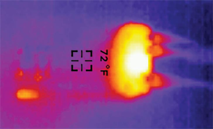
The RaspPi Zero is the warm blob (yellow rectangle) on the right side of the figure. The smaller warm blob at the lower left I think is where I held the PCB before taking this image. Seeing this makes me wonder if the heat generated by the Pi means batteries inside the airframe won’t need a hand warmer.
The Raspberry Pi runs hotter than the rest of the flight computer PCB (printed circuit board) or PICAXE. Based on a recommendation of one of my near space friends, Mark N9XTN, I took a thermal image of the powered-up flight computer.