Crystal Set Schematic Correction
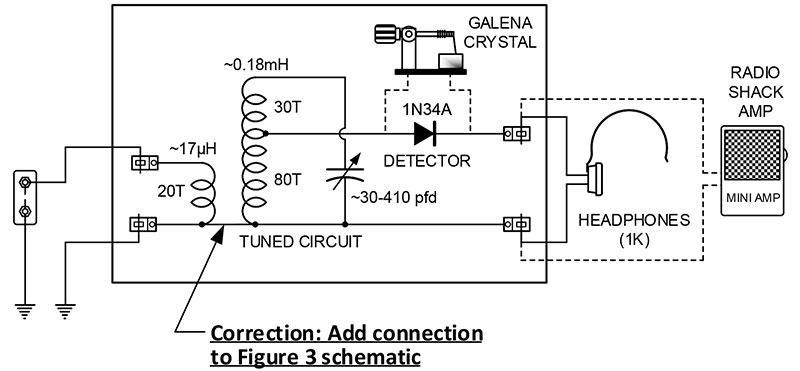
I have a question for David Goodsell regarding his article, “Remembering The Crystal Radio.” My question is regarding the schematic in Figure 3 vs. the Figure 1 picture. It appears the schematic shows the second coil connected differently from the coil in Figure 1.
J.M. Jacobs
Regarding the Crystal Radio article in Issue-1 2020. The schematic in Figure 3 is missing a ground wire. There should have been a ground connection to the bottom of the secondary winding, the tuning capacitor, and the lower headphone clip, as can be seen in the Figure 1 photo. Please see the corrected schematic here.
David Goodsell
A Gray(mark) Area
Thank you for “Remembering The Crystal Radio” by David Goodsell.
The Allied Crystal Radio is very similar to the Graymark 501 Crystal Tuner that I made when I was in shop class (taught by Mr. Wiger at Columbia Junior High/Columbia Heights, MN).
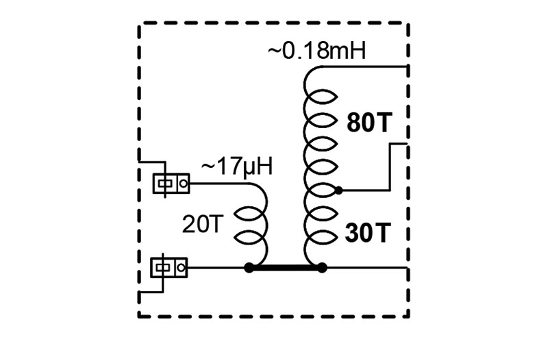
Both radios have a 1-1/2“ diameter coil with two taps and are wound as follows: From one end (point A), 20 turns are wound to the tap at point B (with a 3/16“gap). Next, 30 turns are wound to the tap at point T. Finely, 80 turns are wound to the other end (point C).
The Allied Radio is wired a little differently from many of the Graymark 501s. This includes the one I made.
The Allied has the antenna connected to the “A” end of the coil and the ground connected to the tap at point B (with a 3/16” gap).
My Graymark 501 has the ground connected to the A end of the coil and the antenna connected to the tap at point B (with the 3/16“gap). Point B is not connected to ground.
In other words, the wires going to the coil at points A and B (the 20 turn segment) are “switched’ when compared to the Allied set.
Schematic diagram images for the Graymark 501 can be found on the Internet. I’ve found Graymark schematic diagrams for both wirings. I think the “switched “wiring is the newest and most common of the two wirings.
This “switched” wiring works. I don’t know how it works or why Graymark changed to it. All I know is that Graymark kept the 3/16” gap in the instructions (and on the coil template) and kept the terms primary coil and secondary coil in the instructions (and in the discussion of circuit theory).
Can you explain how this “switched” wiring works (in simple terms) and suggest a possible reason why Graymark changed to it? I’m sure many readers remember this mysterious change in wiring. Thank you.
John Van Pilsum
The Figure 3 schematic on Page 73 should be corrected as follows: 1. Add a horizontal connection between the bottoms of both coils, thereby producing a continuous ground from the lower left clip to the lower right clip. 2. The larger (secondary) coil should be labeled 30T (30 turns) on the lower portion and 80T (80 turns) on the upper portion.
David Goodsell
Lovin’ Nuts
Just received Issue-2 Volume 41 and am enjoying it thoroughly. Thank you very much, and the vintage restoration information is awesome.
Harvey Edwards
Checking Capacitors
I really enjoyed reading Bryan Bergeron’s articles on old radio repair as appeared in Issue-1 and Issue-2 2020.
I did have a question: In Issue-2 on page 88-89 on the Telefunken 516, Bryan references how to check new capacitors to identify the outer shell (shield) of modern replacement capacitors by using an oscilloscope. He refers readers back to the article on the Zenith Restoration, which I assume is the article on pages 84-92 in Issue-1.
However, I can find no information in that article on how to test capacitors with a scope to identify the shield.
Can you refer me to what page(s) this information is on? If it was an oversight and the information was not actually published, perhaps you can have a short article on how to do this in the next issue of Nuts & Volts.
Mr. Carlson’s Lab on YouTube has some videos showing this method from a few years ago. Since then, he has developed a self-contained unit that is much more sensitive.
I have had very limited success using a scope here at my home shop to identify conclusively which is the outer shield connection.
I was hopeful that perhaps you had come up with a more conclusive test setup.
Again, thanks for the articles and information.
E. Kirk Ellis KI4RK
In short, 60 Hz hum pickup will be less when the outer shield side of the capacitor is connected to the ground lead of the scope. A simple A-B comparison can be used.
I love Carlson’s Lab — especially since he moved into his new space. And I’m familiar with his circuit (although I’m not a Patrion member).
I’ve found the scope method to work well for my audio applications; very small value capacitors and larger value caps with a superior design don’t show any relative difference in noise, and that’s all that really matters. At least to me.
If I can’t hear or see (on a scope) any difference in a non-polarized cap, then I’ll just mount it so it looks pretty (so that I can easily read the value).
Although I haven’t tried, I imagine another quick test is to use a capacitance meter to measure capacitance difference, depending on which end is held.
I’ll put that on my “to do” list.
Bryan Bergeron
Vintage Question
I thoroughly enjoyed the article “Restoring a Vintage Zenith Table Top AM/FM Receiver” in Issue-1. I have a question about replacing the two pilot/dial lights with LEDs: In many older tube radios, wasn’t the pilot light wired with the tube filaments in a way that, if the pilot light burned out, there would be extra current draw through the tube filaments, thus shortening tube life? It may have been a non-issue for the particular radio restored in the article, but for other sets, how would a restorer compensate for that issue?
Eric Collins
Glad you enjoyed the article!
Great question! Yes, some of the older radios skimped on a filament transformer by using line voltage and placing the filaments in series, just like those pesky Christmas lights. In those receivers, replacing the lights with LEDs would indeed be problematic. You’d probably have to add a parallel resistor to each LED.
That’s not something I’d want to do because it would be a sizeable resistor in terms of wattage. However, as far as the Zenith goes, I have two sets behind me — each with LED lights — and they’ve been playing perfectly for years.
However, let me amend that.
The pilot lights are wired independent of the tubes. The tubes filaments are, in fact, in series in this model. Zenith added a 6V transformer just to have that little bit of light on the dial. Amazing cost/benefit, if you ask me, but they did it.
So, while my initial answer was correct (pilot lights burning out don’t affect the tubes), you were correct in your knowlege of the series arrangement of the filaments.
BTW, this isn’t the case with German radios of the same era. As you’ll see from the German tabletops that will follow, they all use a transformer for filament and high voltage. Much safer to work on.
Thanks again for the question!
Bryan Bergeron
Thanks for the follow up. The question still bugged me because I knew I remembered reading it somewhere, so after some digging I found this link: https://www.philcorepairbench.com/blown-pilot-lamps-and-35z5-open-filament.
Eric Collins
Heated Advice
I’m enjoying the vintage radio restoration articles. Bryan Bergeron’s work will likely encourage others to try their hand at this rewarding hobby.
Perhaps a few words of advice should be shared with those just starting out. Care should be taken when replacing panel lamps as they can have an effect on tube filament current and voltage.
For example, in radios with a 35W4 rectifier, the proper lamp or equivalent should be chosen, as this can affect tube life. Many AA5 AC/DC sets used series string filament supplies, with the panel lamps as part of the string. It’s important that the correct bulbs (or calculated equivalents) be used to preserve heater life.
As you have pointed out, readers should note that the older radios did not have a polarized AC line plug, and that one side may go directly to the chassis, as is the case with AC/DC sets.
The chassis has a 50/50 chance of being the hot side of the line. Be careful!
Paul Mondok AA2PM
Thanks for taking the time to write. And I hear you on the restoration articles — we plan to have one in each issue.
Great pointers re: lamp selection, especially on those older sets. Readers will benefit from your advice.
Bryan Bergeron
Back to the Future
Your editorial “The Joys of Retooling — Again” was great! I have followed a similar path to return to the tube electronics of my early days.
I find the joys of hollow-state circuits to be just as fun as I remember!
I haven’t given up on solid-state, I’m just taking a senior moment (break).
Keep up the good work — I have been a Nuts & Volts lifetime subscriber since 1986.
William Hanson
Appreciate the note. Like you, I’m enjoying a lapse into hollow electronics for a bit of nostalgia. However, I’m gearing up for several projects in robotics for our sister publication, SERVO Magazine.
Bryan Bergeron
Shocking Memories
I enjoyed your Developing Perspectives column along with the Restoring a Vintage Zenith Radio article. The isolation transformer and autotransformer along with the series light test for no shorts brought back memories.
When I first began teaching in 1970, the lab I had to teach in had exactly zero isolation transformers! When we started the TV repair portion of the course, my first lecture/demonstration was how to make certain the chassis was connected to the neutral side of the AC line.
Simple AC measurement from the chassis to an earth ground. I had checked the outlets and verified that the outlet cover screw was an earth connection.
Working with students with a minimum amount of experience, I didn’t trust them to do this correctly every time. My pocket always contained a neon lamp tester (470K ohms in series with an Ne 2 commonly) that I would use to check the chassis for the presence of the hot wire.
A simple touch of one lead to the chassis while the other lead was in contact with my hand. A small glow from the neon let me know that chassis was HOT!
Review and discussion of the procedure would then occur. I still have several of those two lead neon testers and use them when working on home wiring.
It took me several years to convince the powers that be (money controllers) that all labs needed isolation transformers and that they should be utilized for every hot chassis radio or TV. While working in the lab with a hot chassis, I wouldn’t trust any student telling me that the chassis was not hot.
I always checked with my neon tester and if cold, praised them for doing it right. Otherwise, there would be retraining.
My associate instructor believed a student and made the mistake of putting his hand on the metal lab stool and touched the chassis ... instant 120 VAC shock which fortunately he was able to jump away from.
Neither of us had considered the existence of a floor drain in that room and that was what one leg of the lab stool was setting on! There was an immediate halt to all lab activities.
I had a 120V 100W lamp I used to assist in locating line input shorts (your dim bulb reference) that I connected to the chassis and the lab stool. Members of the class could not detect the difference between that connection and plugging the bulb into a socket!
We were lucky that day and able to turn a scary experience into an important safety lesson.
Several years after getting the labs supplied with isolation transformers for every bench (36 total in three labs), we started having the isolation transformers burning up. I was told it was happening because they were getting old. I didn’t believe that but still didn’t understand why it was happening. A good amount of smoke from one transformer required me to run over and unplug everything. I started looking for the “why.”
What had happened was the transformers were purchased in 1973 or 1974 when most of the TVs were black and white. Color TV had become the larger portion of the TVs we were using for lab sets and the higher current draw of the color sets was greater than the isolation transformer’s rating. We restocked the labs with higher rated isolation transformers.
One more isolation transformer story and I’ll quit. I was working for American Desk out of Temple, TX. They had a contract to install a video distribution system in all of a college’s classrooms and lecture rooms. They were supplying RCA color TVs with a hot chassis. Part of my job was to hard-wire the TVs to an isolation transformer which was controlled from the lectern. I accepted a field service position to provide service at that site. On a service call to that college, I discovered a large pile of the isolation transformers in the storeroom.
Inquiring about where they had come from (I knew), I was told they had been removed from the TV mounts because they were causing noise in the distributed audio. (They weren’t, but that was always the complaint and I could not measure any noise values greater than -70 db on the system.)
I informed my boss that dead instructors would have no use for the lectern or the TV.
I went home and sent my boss a letter informing him that I was resigning the service position and why, suggesting that they might want to increase their insurance coverage or have their lawyer take a look at the contract with that college.
Love my neon lamp tester!
Simple but effective.
George Shaiffer
Excellent first-hand accounts of why isolation transformers are worth their weight in copper.
I had my share of shocks as a kid working on B&W TVs until I landed my first surplus isolation transformer. Probably why I’m still around today.
Your stories really bring home the need to take precautions when working with 110 VAC and potentially hot chassis.
Bryan Bergeron