I built a crystal radio in 1952 when I was 12 years old. It came as a kit from Allied Radio in Chicago for $2.50. I spent many an hour down in our basement with headphones clamped on my ears, carefully tuning the variable capacitor to pull in nearby and distant stations. Some were so faint that my young imagination thought I might be hearing secret messages.
Nowadays, all you have to do is ask Alexa to tune into any one of hundreds of radio stations to hear their programming. No more uncomfortable Bakelite headphones. In this article, I’d like to share how the primitive crystal sets of the ‘50s and ‘60s worked and hopefully stir some distant memories for those of you who also built one of these mysterious listening devices. BTW, Etsy sells a number of vintage-style crystal sets on its website made of real wood, not plastic! No batteries required.
RESTORING MEMORIES
Figure 1 shows the restoration of a crystal set I found on eBay that was very familiar to me.
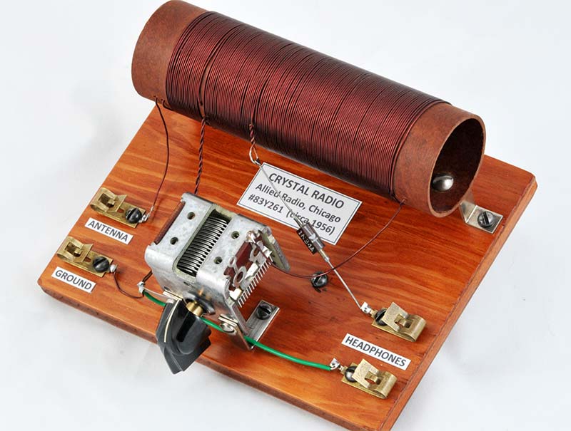
FIGURE 1. This restored crystal radio kit from Allied Radio in Chicago cost $2.50 in the 1950s and ‘60s.
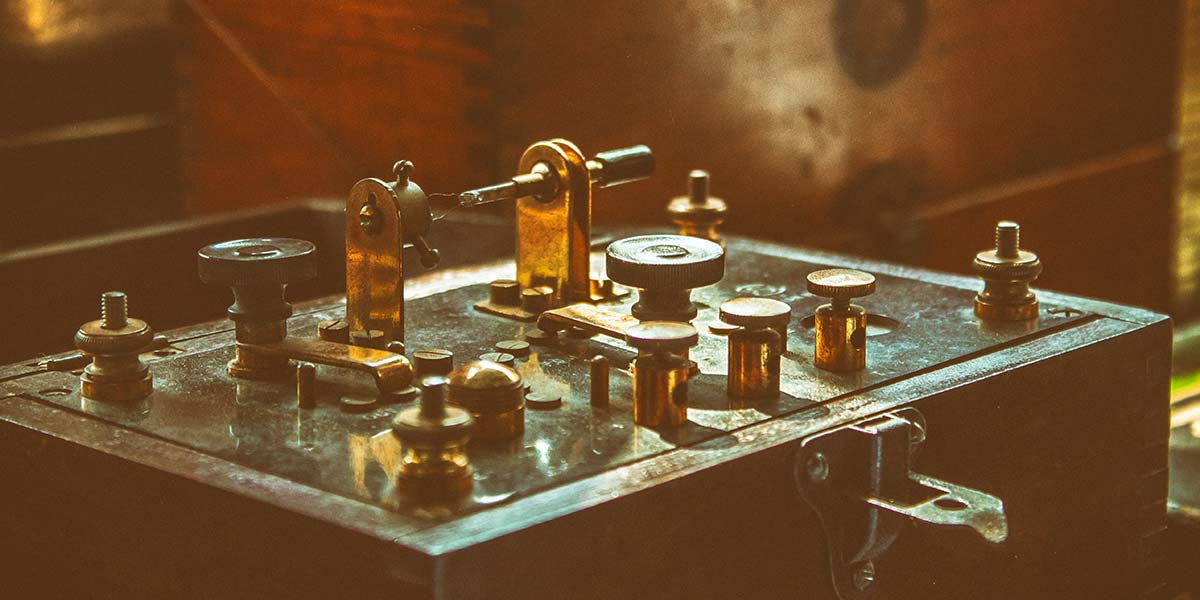
In fact, it was exactly the same model I originally built decades ago. I don’t recall what happened to my old set; perhaps my mother tossed it out after I left it in the attic. Figure 2 shows the unrestored unit I received. It obviously needed some TLC.
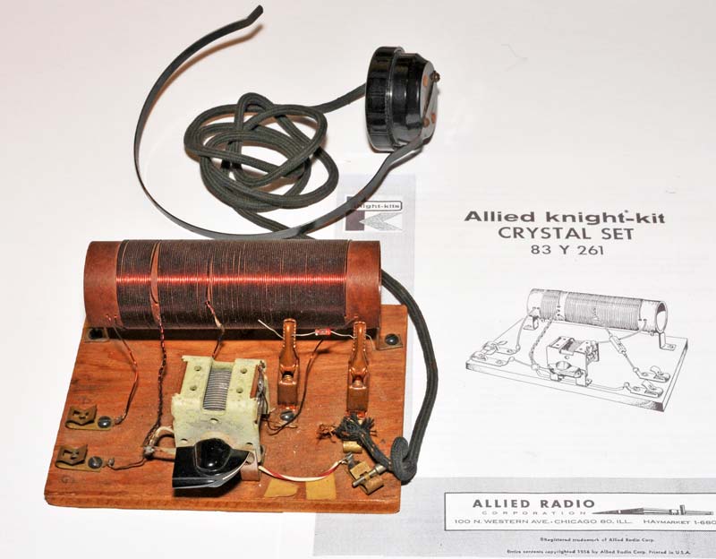
FIGURE 2. This unrestored crystal set was found on eBay and came with a headphone. It needed some TLC.
One thing I remember about building my first set was that I fried the 1N34A germanium diode. At that time, our family only had a huge 100 watt Weller soldering gun and I grossly overheated the poor little diode. It cost $0.43 for a replacement from Allied. Fortunately, my soldering equipment and skills have improved over the years. As a kid, I also had trouble winding the big coil. It kept loosening up as I wound it, so my dad patiently helped me wrap it tight.
SIMPLE SCHEMATIC, LONG ANTENNA
Crystal sets receive AM (Amplitude Modulated) radio stations by using a simple demodulation scheme. The schematic is shown in Figure 3.
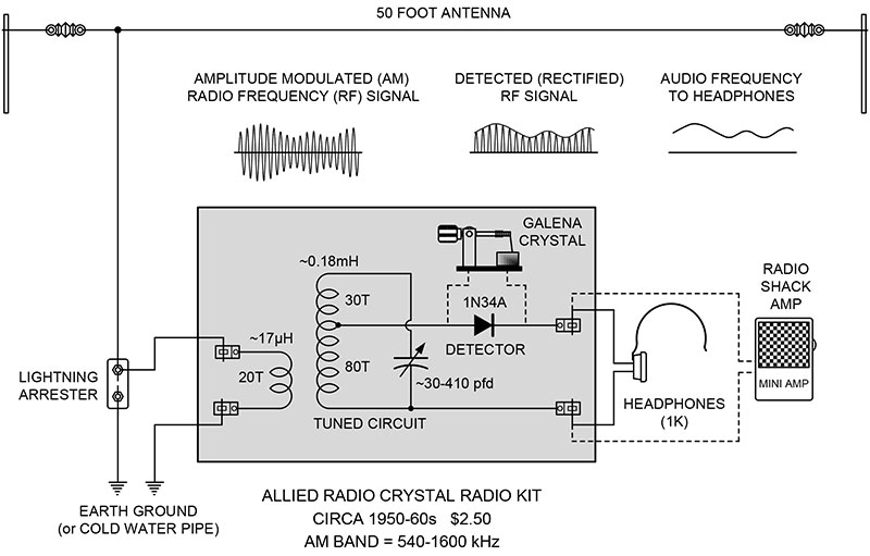
FIGURE 3. Early crystal radios used a natural galena crystal instead of a germanium diode to detect the audio modulation.
The 1.5” diameter coil and variable capacitor form a resonant circuit to select the frequency and a diode rectifies (demodulates) the modulated radio frequency carrier. If there wasn’t a diode, the modulation would simultaneously produce equal and opposite alternating voltages which would average out to zero in the headphones. No sound.
The diode strips off one polarity and the headphones respond to the resultant pulsating direct current. The waveforms at the various stages are included in the Figure 3 schematic. For a more in-depth explanation, please see the excellent crystal radio and crystal detector entries on Wikipedia.
The manual for the Allied set has a diagram of a suggested 50 foot inverted L antenna configuration. I decided to recreate it exactly as it’s depicted in the manual and Figure 3. Figure 4 shows the vintage insulators and lightning arrester that I found on my favorite website. Note the “less than” mint-condition of the box the arrester came in.
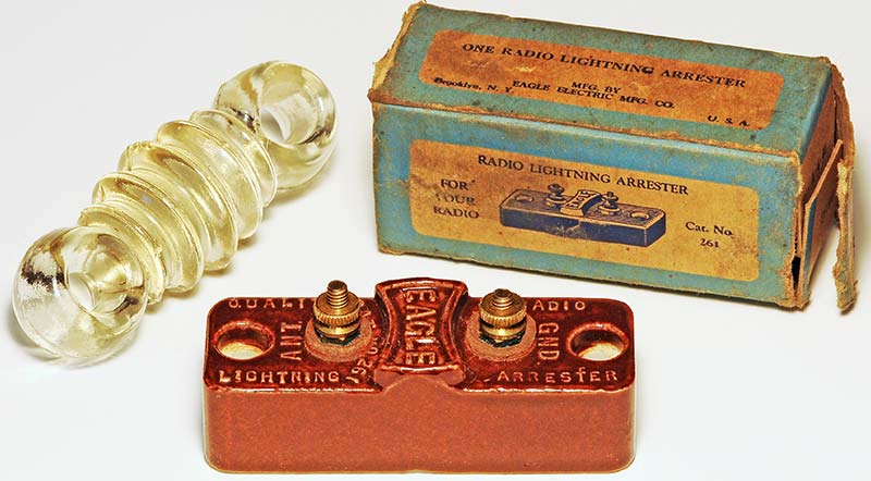
FIGURE 4. An outdoor antenna used a lightning arrester for protection and glass insulators to isolate the receiving wire from ground.
MAXIMIZING EFFICIENCY IS THE TRICK
The hidden magic of crystal radios is that they’re able to capture almost infinitesimal amounts (nanowatts to microwatts) of power from distant transmitter stations and efficiently convert it to sound for our ears. No batteries. No amplifiers.
The Allied Radio design maximizes efficiency by using an inductively coupled transformer with a 20-turn primary winding to better match the impedance of the antenna.
The secondary is tapped for the detector diode at a point that reduces loading of the tuned circuit and improves the impedance match with the detector.
Finally, a high impedance headphone converts the demodulated audio signal to sound.
LET’S CHECK THE COMPONENTS WITH AN LCR METER
Just for fun, I thought I’d measure the approximate values of the resonant circuit components when tuned to a 960 kHz station. I used one of those little LCR Component Testers advertised on the Internet. They only cost $19 or less and are fairly accurate.
Figure 5 shows the measured secondary coil.
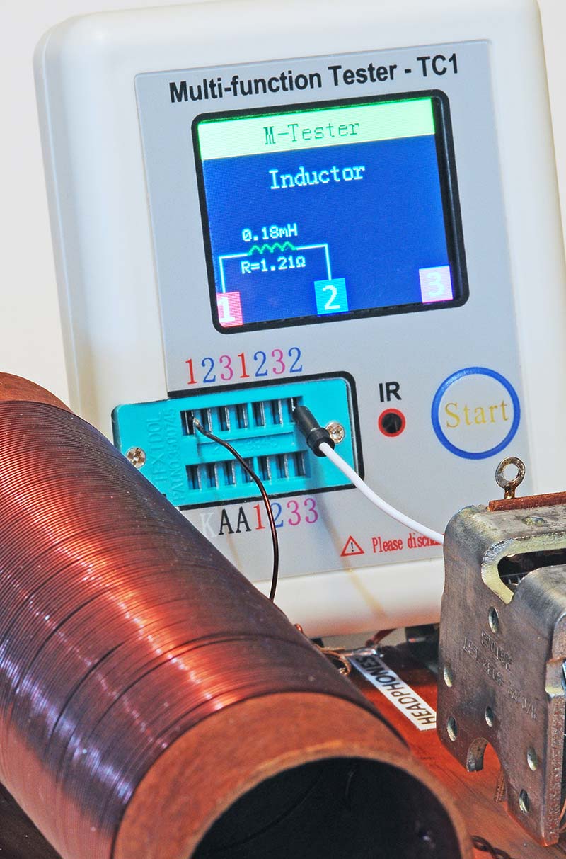
FIGURE 5. The 1.5” diameter coil and tuning capacitor measured 0.18 mH and 154 pfd when tuned to 960 kHz.
It read 0.18 mH, which lined up pretty close to an on-line inductance calculator. The on-line calculator said the inductance should be 0.176 mH for that size of coil. Right on the button.
Lastly, I measured the variable capacitor when it was tuned to the 960 kHz station: 154 pfd.
Resonant frequency:

So, 0.18 mH(L) and 154 pfd(C) = 956 kHz (vs. 960 kHz broadcast). Darn close!
POKING AROUND A GALENA CRYSTAL
Some earlier crystal radios used a special kind of detector called a galena crystal. Galena is another name for the crystalline mineral Lead Sulfide (PbS). Figure 6 shows a small piece of galena crystal buried in a little round slug of low temperature solder with a whisker above to make contact with the surface.
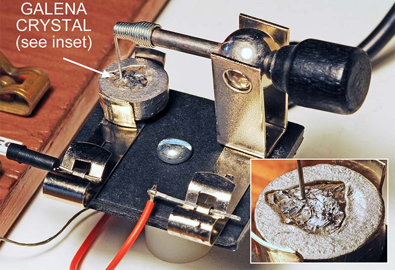
FIGURE 6. The galena crystal required poking around its surface with a tiny “whisker” to find an area with good reception.
It wasn’t a sealed unit like the 1N34A. In fact, you had to gently poke around the irregular surface of the galena with the tiny whisker in order to make it work. Only certain areas would act as rectifying junctions and exhibit diode characteristics.
Figure 7 shows the diode curve traces I got from a galena crystal, 1N34A, 1N914B, and 1N4007.
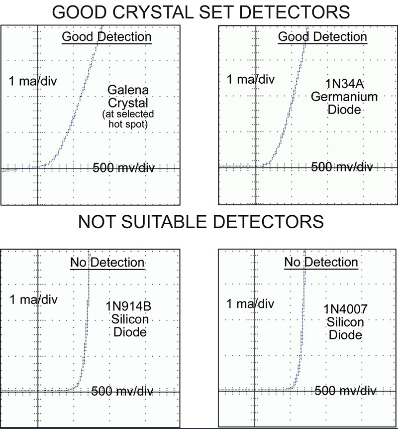
FIGURE 7. Curve traces of various diodes show the superior performance of galena and germanium diodes for this application.
Silicon diodes make poor detectors because their knee occurs at a voltage too high for the weak signals found in crystal radios. A video showing me poking around a galena crystal to find the best radio reception can be found at https://youtu.be/auz64mtoVLY.
THE FUN OF TUNING IN STATIONS
One last thing. I happened to have a small battery-powered RadioShack audio amplifier, so I attached it in place of the headphones. Zowie! One of the stations boomed out. Very loud!
looked it up on Google and found that the broadcasting antenna was only four miles from my location and it was putting out 5,000 watts during the day! No wonder it was so loud! Fortunately, the station reduced its power to 20 watts each evening and I was able to tune in a few other stations.
Even after all these years, it was still exciting to tune around the band and see how many stations I could pull in. Maybe I’ll put up a longer T antenna and do some real DXing.
To sum it up, I’ve enjoyed revisiting an exciting time in my youth and hope that you’ll consider introducing your kids and/or grandkids to the world of crystal sets. Please feel free to contact me at [email protected] for any comments or to share your experiences.
P.S. If you still have a vintage crystal set tucked away in a closet, you get a gold star. LMK. NV