Explore the world of tube-type electronics by restoring this classic 1961-1962 AM/SW/FM broadcast receiver: the Telefunken Jubilate 5161W from West Germany.
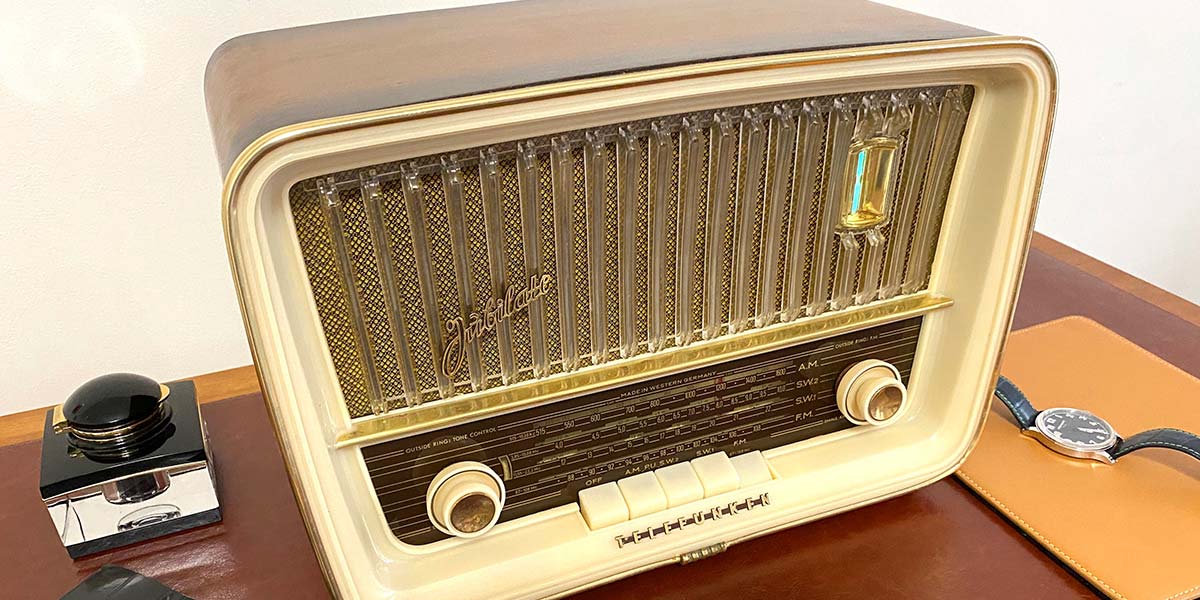
This article continues the exploration of vintage tube broadcast receivers that we started with the restoration of a domestic Zenith radio in Issue-1 2020. The Jubilate (Figure 1), which means “to show great happiness; rejoice” is considerably more complicated than the Zenith. Prices on eBay for a Jubilate that “works” start at around $175. The Jubilate makes a great second restoration project but may not be the best starter radio if you’re new to restoration and have no experience with tube circuitry.
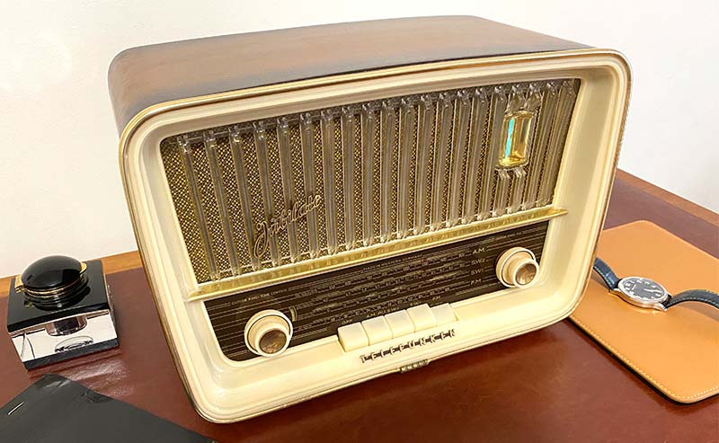
FIGURE 1. Restored Telefunken Jubilate 5161W.
Every restoration — even repeat restorations of the same model — reveals something new about tubes and tube circuitry. In this restoration of the Jubilate, the focus is on reclaiming a circuit board covered with dirt; converting a selenium power supply to one based on silicon diodes; and the best ways to rejuvenate the cosmetics of your radio, including how to refinish a wooden cabinet.
German Tabletop Vintage Radios
You probably won’t be surprised to learn that, for a given year, the best German-made tube-type tabletop radios are more advanced (from an engineering perspective) than those from the US. Brands like Telefunken, SABA, and Grundig are legendary.
In my experience, the top Telefunken broadcast radio receiver — the Opus — is one of the best sounding vintage tabletop receivers ever made. The SABA wins the title of most technologically advanced, while the Grundig (once the largest radio manufacturer in Europe) is the longest lived.
Telefunken Jubilate 5161W
The Telefunken Jubilate 5161W is a classic example of what was produced by Telefunken Deutschland in the 1961-1962 period. It’s one of the smaller tabletop radios produced by Telefunken, at about 14” x 9” x 9” and weighing in at 12.8 lb (5.8Kg). The six-tube receiver — designed for export to the US — covers the US FM band (88-108 MHz), the standard AM broadcast band (535-1605 kHz), and two AM shortwave bands (3.85-10.05 MHz and 11.55-22.5 MHz). The Jubilate has a curved faded wood veneer, a forward-facing 5x7 moving coil speaker, and an audio output of a little over five watts.
The six-tube receiver follows the typical superheterodyne architectures for broadcast AM/SW1/SW2 as shown in Figure 2.
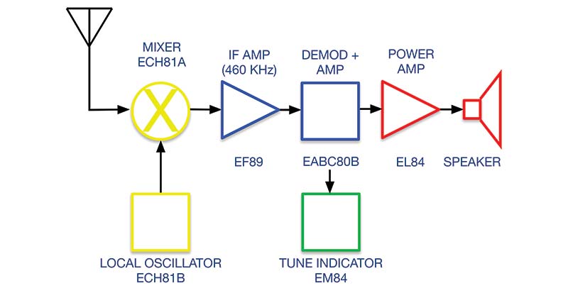
FIGURE 2. Jubilate’s superheterodyne AM receiver architecture. Filters not shown for clarity.
The FM architecture is shown in Figure 3. In the AM mode (used for broadcast AM as well as the two shortwave bands), the broadcast signal from the antenna is mixed with the signal from the local oscillator. The 460 kHz (not 455 kHz) intermediate frequency signal is selectively amplified, converted to audio by an AM detector (demodulated), and subjected to two stages of amplification.
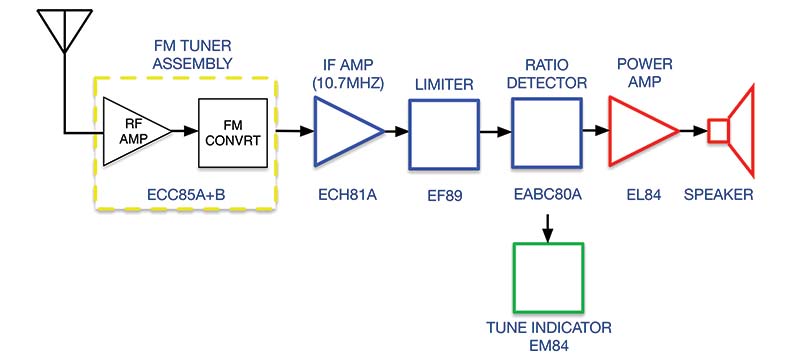
FIGURE 3. Jubilate’s superheterodyne FM receiver architecture. Filters not shown for clarity.
The tuning is indicated by a narrowing of the gap in the tuning indicator. The tubes, their function in the AM mode, and their TubeDepot.com price (at the time of this writing) are listed below. Note that the “A” and “B” suffix indicate two complete tubes within a single glass envelope. For example, the EABC80 is a combined triode and triple diode used as an AM amplifier, AM detector, and FM ratio detector.
ECH81A — Heptode AM mixer ($10)
ECH81B — Triode AM local oscillator
EF89 — Pentode AM IF amplifier ($44)
EABC80B — Triode AM amplifier; diode AM detector ($15)
EL84 — Pentode 5.7W power amp ($13)
EM84 — Double triode tuning indicator ($15)
In the FM mode, the broadcast signal from the antenna is processed by a sealed FM tuner assembly that contains an RF amplifier and FM converter. This converter is used as a “black box” source of FM broadcast signals throughout much of the Telefunken product line. The output of the converter (a 10.7 MHz intermediate frequency signal) is fed to an IF amplifier and then on to the limiter. The output of the amplitude limiter is fed to a ratio detector and then a low-level audio amplifier. This audio signal is then fed to a power amplifier and on to the speaker. The six tubes and their function in the FM mode are:
ECC85A — Triode RF amplifier ($38)
ECC85B — Triode FM converter
ECH81A — Heptode IF amplifier ($10)
EF89 — Pentode limiter ($44)
EABC80A — Diode pair ratio detector ($15)
EABC80B — Triode audio amplifier
EL84 — Pentode 5.7W power amp ($13)
EM84 — Double triode tuning indicator ($15)
Refurbishing the Jubilate requires a detailed schematic, as well as specific tuning instructions. You can download a PDF of the full schematic along with normal voltage and resistance measurements, as well as tuning instructions from the Sam’s PhotoFact site (samswebsite.com) for $15 (PhotoFact 635, Folder 11).
A PDF of the full schematic only is available from Turntable Needles (turntableneedles.com) for $7. I was fortunate because the previous owners left the original schematic inside the unit.
INSTRUMENTS
At a minimum, you’ll need an isolation transformer, variable autotransformer, and a dim bulb current limiter. The isolation transformer will help isolate you from coming in direct contact with the 117V mains voltage. The variable autotransformer (or Variac™) and dim bulb current limiter enable you to limit the power going into the radio, and therefore minimize chances of damaging any components. You’ll also need a vacuum tube voltmeter (VTVM) or digital multimeter (DMM) for voltage and resistance measurements. Some form of capacitance meter and a tube tester are nice to have, but not necessary.
Consider using your smartphone or tablet computer to document the restoration process — especially the original location of wax paper and electrolytic capacitors.
RESTORATION PROCESS
Restoration is a logical process that begins and ends with careful detailed inspection of the radio. Avoid the urge to plug in the radio mains. By the time you smell smoke, it will be too late.
External Inspection
Figures 4-8 show the external state of the Jubilate as I received it from an eBay store. As you can see in Figures 4 and 5, the front of the unit is dirty, the tuning display is barely legible, the grill cloth is stained, and the brass trim is heavily corroded.
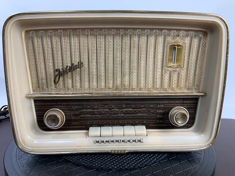
FIGURE 4. Before restoration, atop my 15” diameter swivel.
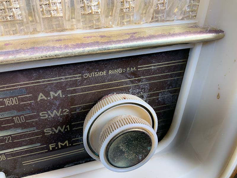
FIGURE 5. Close-up of brass trim, glass panel, and AM/FM tuning knob.
The band select pushbuttons are stained and covered with a sticky substance. The back panel (shown in Figure 6) is in excellent condition, with no indications of rain or other damage. Note the vacuum tube placement chart on the back panel.
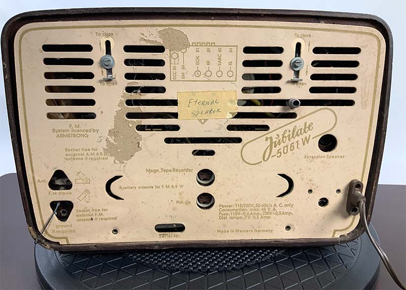
FIGURE 6. Back panel, showing tube layout.
The original thick lacquer finish on my Jubilate is cracked, with occasional pitting (see Figure 7).
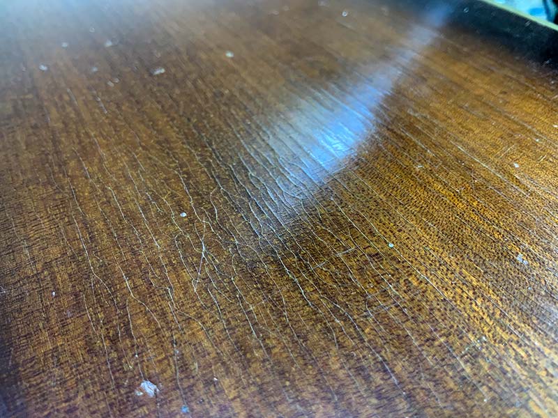
FIGURE 7. Pitted and cracked original finish.
Although the deep cracks are not obvious from a few feet away, the relatively thin wood veneer is exposed to the elements and should be protected. Lastly, examine the two-prong, non-polarized power cord. The cord on my unit (Figure 8) shows typical fraying at the cord-connector joint. You should expect to replace the power cord on your unit. Options range from NOS cords on eBay for $50 or ordinary “TV cheater cords” for $8.
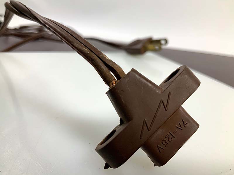
FIGURE 8. Frayed power cord; two-prong, 125V @ 7A.
Internal Inspection
The next step is to open the back cover and inspect the inside of the radio (see Figure 9).
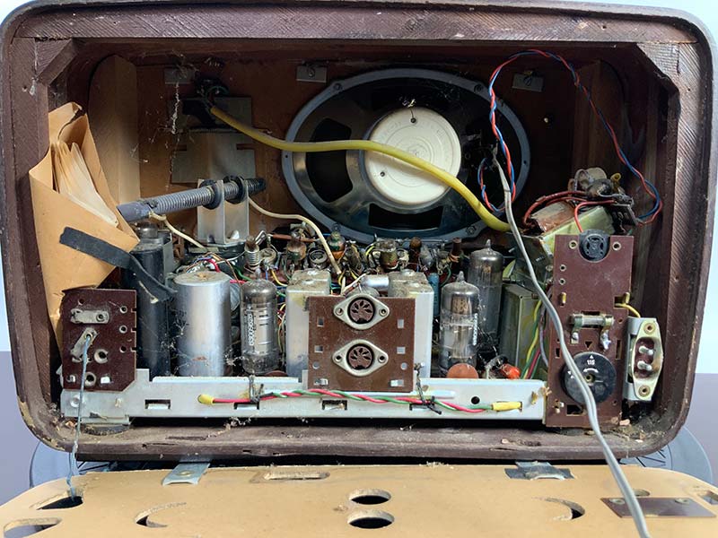
FIGURE 9. Component view with back removed.
As you may be able to make out in Figures 10-12, the components in my set are covered in a layer of dust, dirt, and some type of oil. In my experience, any sort of oily residue on a circuit board is due to the overzealous use of DeoxIT ™ or similar contact cleaner that leaves a “protective” residue.
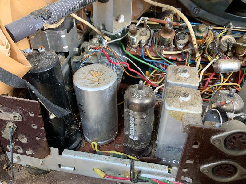
FIGURE 10. Power rectifier and capacitor behind antenna input.
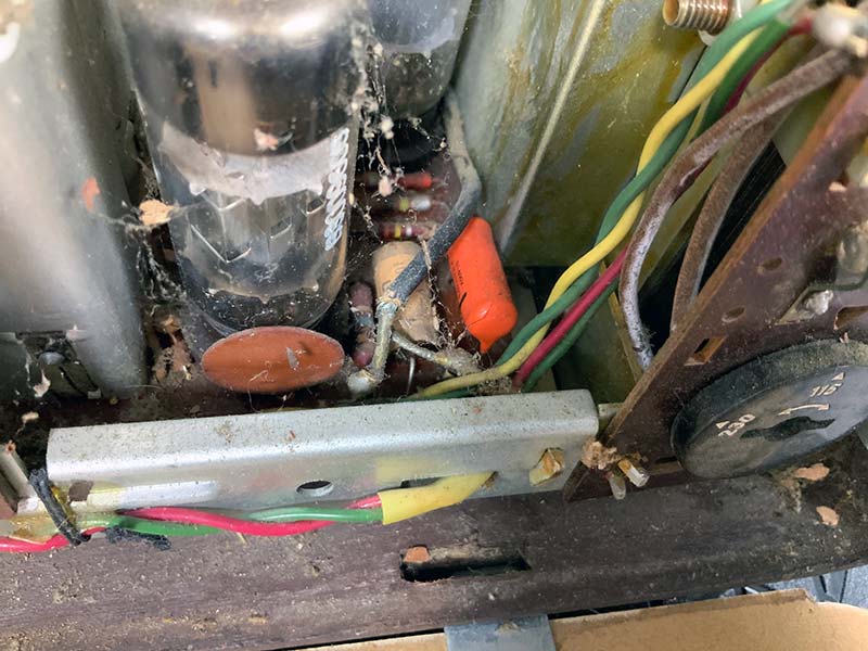
FIGURE 11. Transformer tap selector (right). Note spider web, leaves, and other debris.
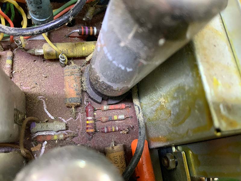
FIGURE 12. Close-up of dirt/oil mix covering the PCB and components.
In Figure 9, you can see the single speaker in the center of the unit; the voltage selection switch and fuse to the right; and the aluminum electrolytic can capacitor and black selenium diode can to the left. The original schematic with tuning instructions is in the envelope on the left — an unexpected find. Note the power transformer which — in addition to supplying plate and filament voltages — isolates the power main from the chassis. If you recall, the Zenith radio had no such isolation, but was connected directly to the mains.
Next, work your way through the set, photographing the position, value, and voltage ratings of the wax paper capacitors and electrolytic capacitors. Every original wax and electrolytic capacitor will have to be replaced. Similarly, note the position of the black selenium rectifier can, which will have to be replaced with a silicon rectifier and a power resistor, zener diode, or power MOSFET.
Check the condition of the 5x7 speaker, including the mounting hardware. I tested the integrity of the speaker by feeding it with the audio from another receiver. In my case, the speaker was fine, but was a little lacking in bass response. I marked the speaker for replacement with a full-range, high-end ($80) coaxial speaker with a bass response more to my liking.
“Working” vs. “Restored”
Electronics on eBay (including vintage broadcast receivers) are typically listed as “Working,” “Restored,” or “Needs Work/For Parts,” and are priced accordingly. At the high end, restored receivers are fully restored, with new capacitors, insulators, potentiometers, and any other parts required to bring the receiver up to specifications.
The most common description — working — means that the radio makes sound when plugged in, but will require new capacitors at a minimum, as well as retuning. Needs work/for parts is self-explanatory. Often, you can pick up a new set of vacuum tubes at a bargain price from one of these units.
Note signs of abuse by a former technician, such as cold solder joints, burned insulation, and poorly rebuilt potentiometers. Use the vacuum tube map on the back cover and remove the tubes, verifying tube type and location. Improper substitution of tubes is common in vintage gear, and a common cause of catastrophic problems such as power transformer burnout.
If you have access to a tube checker, then check the tubes for conductivity, shorts, and transconductance. Gently clean the tubes that pass the tests with a microfiber cloth and store them for later. Check the potentiometers and tuning knobs on the front panel for slippage and seizing. The tone control on my radio (which used a coaxial shaft arrangement with the volume control) was stiff and difficult to turn. Finally, give the unit a gentle shake to dislodge any loose metal objects that might cause problems when you apply power.
Cleanup
Assuming your list of problems and the cost of required parts is reasonable, the next phase of the restoration process is cleanup. Extract the chassis from the wooden case. Using a screwdriver, remove the knobs from the front of the unit, taking care not to damage the felt washers between the knobs and the glass font panel.
Next, remove the four retaining bolts on the bottom of the radio. Remove the front glass panel, clean it gently with a damp cloth, and set it aside. With the glass removed (refer to Figure 13), you have full access to the circuit board, components, and controls.
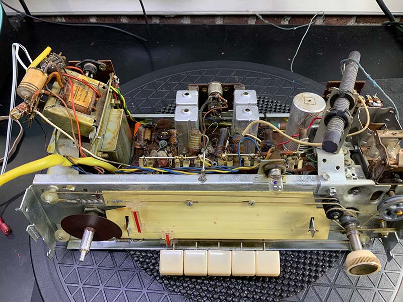
FIGURE 13. View from the top; chassis free of enclosure. Audio output and power transformers on far left.
Because the circuit board and components were covered with a 1/8” thick carpet of oily dirt, I used a two-step process of a water-based cleaner/rubbing alcohol followed by a solvent-based cleaner. If your radio was also used as a terrarium, you can follow the same procedure.
Otherwise, skip ahead to the power supply upgrade section below. Place the chassis on a folded towel in preparation for fully saturating the carpet of debris with about 4 oz of Super Clean cleaner. With the transformer end down (and the variable capacitor end up), start spraying the cleaner just below the variable capacitor. Maneuver the chassis so that the runoff exits toward the corner of the chassis and onto the towel.
Next, use a stiff bristle brush to break up any clumps of debris and to brush off capacitors and other components. Follow up with a spray of about 4 oz of 93% rubbing alcohol, again moving from top to bottom, with the transformers at the bottom. Finish off this first phase of cleaning with compressed air until the alcohol is removed.
Figure 14 shows the printed circuit board (PCB) and components after this first phase of cleaning.
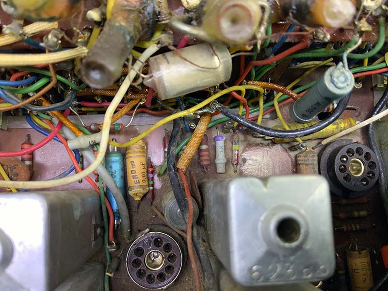
FIGURE 14. PCB after initial cleaning with detergent/rubbing alcohol/compressed air.
The next phase of cleaning involves saturating the board with nearly a full container of CRC QD Electronic Cleaner spray. This means working outside or inside with an incredibly well-ventilated workspace and mask with goggles. Working with the transformers at the bottom, start at the top of the unit. Follow up with compressed air to remove any remnants of the electronic cleaner. A full container of CRC QD cleaner might seem excessive, but it was required in my case to remove the significant oil and debris from the circuit board. See Figures 15 and 16 for the chassis after the two phases of cleaning.
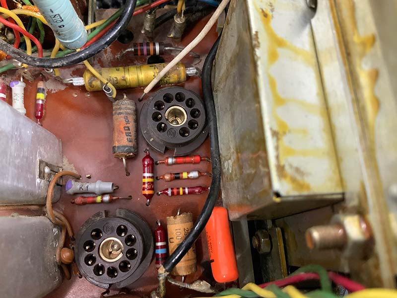
FIGURE 15. PCB after full cleaning.
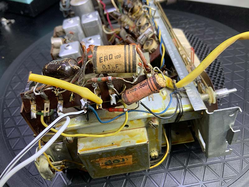
FIGURE 16. Audio output transformer and speaker connections after cleaning.
Power Supply Upgrade
The next step is to upgrade the power supply from the eventually problematic selenium rectifier and electrolytic can capacitor with a silicon rectifier and pair of new electrolytic capacitors. Using a flashlight to backlight the PCB (Figure 17), identify the four leads of the selenium rectifier bridge — two AC, one positive, and one negative lead — before unsoldering the can from the circuit board.
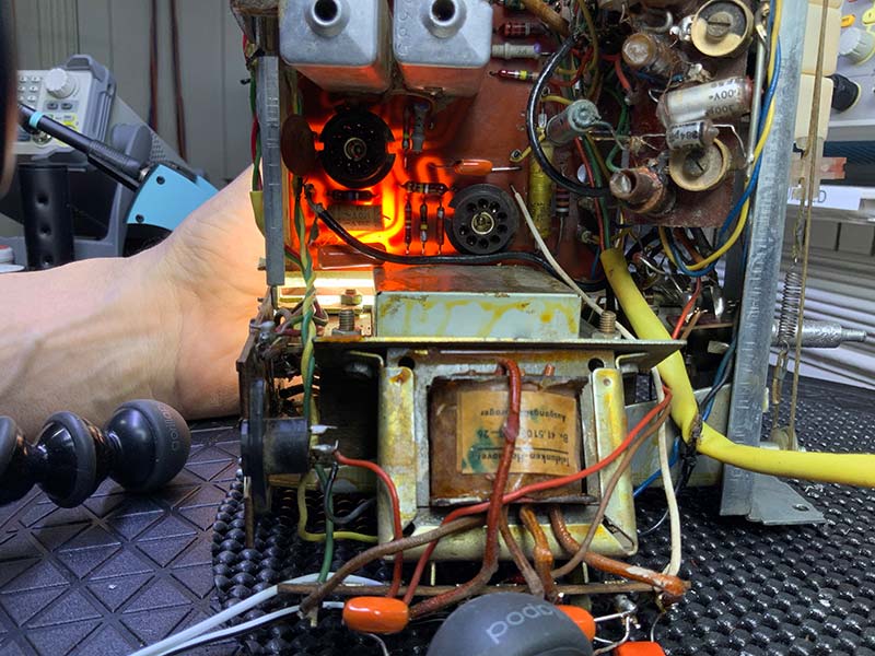
FIGURE 17. Backlighting PCB to trace power supply circuit.
Next, remove the dual 50 µF @ 350V electrolytic capacitor can from the PCB. There are several options for replacing the electrolytic capacitor can: re-stuffing the can with two capacitors; purchasing a custom replacement can from a vendor such as Hayseed Hamfest LLC (hayseedhamfest.com); and replacing the can with two discrete capacitors. I opted to use two discrete capacitors, using the nearest common values, 47 µF @ 450V, as shown in Figure 18.
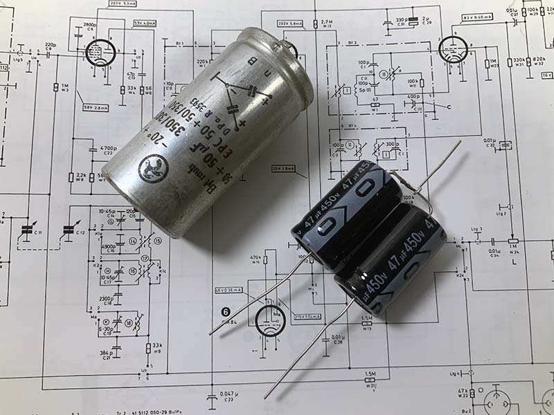
FIGURE 18. Original can electrolytic capacitor (left) and discrete component replacement (right).
Solder the two capacitors in place, noting that nothing is disrupted on the board. A custom electrolytic capacitor can be substituted for the discrete capacitors at any time. Next, install a 600V @ 1A silicon bridge, using the original connections for the selenium bridge. Because the silicon bridge has a lower forward resistance than the selenium bridge, the output of the power supply (as measured at one of the 47 µF @ 450V capacitors) will be higher than specified on the schematic (260V @ 57mA). You’ll need to add a series resistor to the B+ line to obtain the original voltage. Based on my work with similar radios, I used a 330 ohm/5W resistor to reduce the output voltage by about 20V (Figure 19).
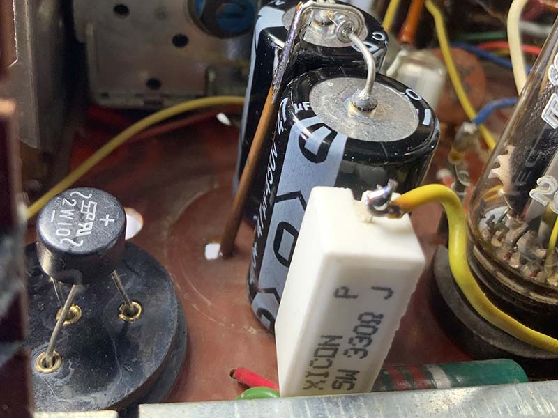
FIGURE 19. Upgraded power supply with silicon diode bridge (left), electrolytic capacitor pair, and white 330 ohm/5W series resistor.
The 330 ohm resistor provides a 330 x .057 or 18V drop. That works out to a generous (.057)2 x 330 or one watt dissipation. I waited to anchor the resistor with silicone sealer until I verified the output in the power-up phase.
Recapping
Replacing the dozen or so electrolytic and wax capacitors with new capacitors is a time-consuming but straightforward exercise in patience. Every potentially problematic capacitor must be replaced with a capacitor of similar value and voltage rating. I used “orange drop” capacitors (see Figure 20) for this project because they’re affordable, easy to use, and robust. When replacing capacitors, try to maintain the position and orientation of the original capacitors, including the outer shell of the wax capacitors. This will minimize the introduction of noise and undesirable coupling between components.
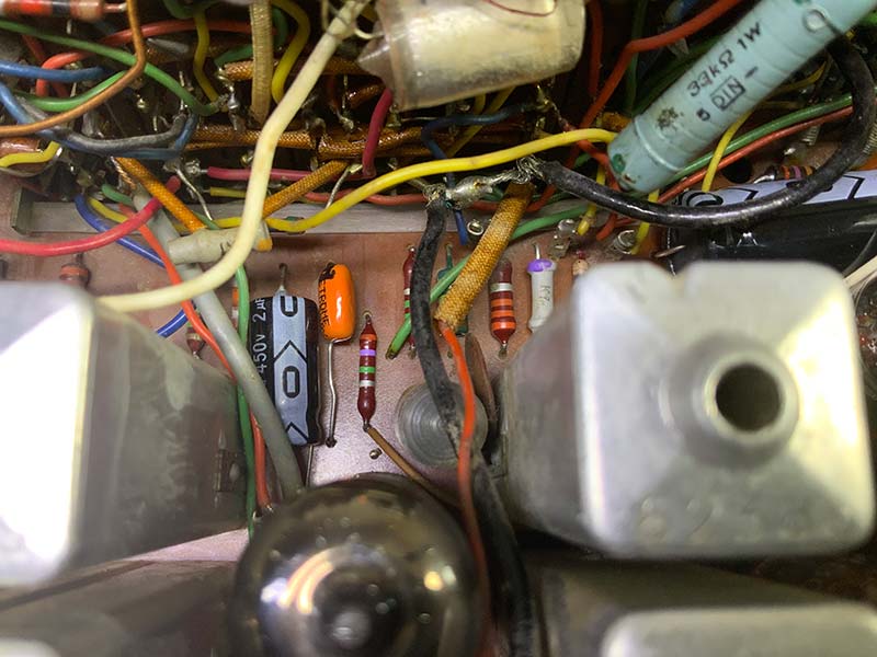
FIGURE 20. New “orange drop” and electrolytic capacitor installed on clean PCB.
Recall from the Zenith project in Issue-1 that unlike wax and paper capacitors, most modern non-electrolytic capacitors lack a polarization mark. As detailed in the Zenith article, you can use an oscilloscope to identify which lead corresponds to the outer shell of the capacitor.
Contact/Potentiometer Cleaning
The next step is to generously spray switch contacts and pots with CRC QD Electronic Cleaner, making sure to orient the chassis so that any debris-carrying fluid drains away from components as it evaporates. Wait 24 hours and repeat the treatment.
After the second application of cleaner, use a cotton swab and fiberglass pen (Bergeon 6240) on the visible rotary switch contacts. Finish off the pots and switch contacts with a carefully controlled, minimum application of deoxidizer spray. Use a paper tower to absorb any extra deoxidizer because it leaves a tacky residue that attracts dust. Again, cleaning with volatile substances is either an outdoor activity or one that occurs in an incredibly well-ventilated shop.
Resistance Check
Replace the vacuum tubes using the diagram on the back panel as a guide. Then, using the schematic as a reference, use an ohmmeter to check for obvious problems such as shorted capacitors and open solder joints. In addition, follow the resistance table that lists resistance to ground for every vacuum tube pin.
If there’s a discrepancy, then address it before applying power to the radio. In my case, the table checked out without a problem.
Power-On
Using a variable AC voltage transformer, an isolation transformer, and dim bulb current limiter (Figure 21), increase the voltage enough to verify operation of the tuning indicator tube and some sound output.
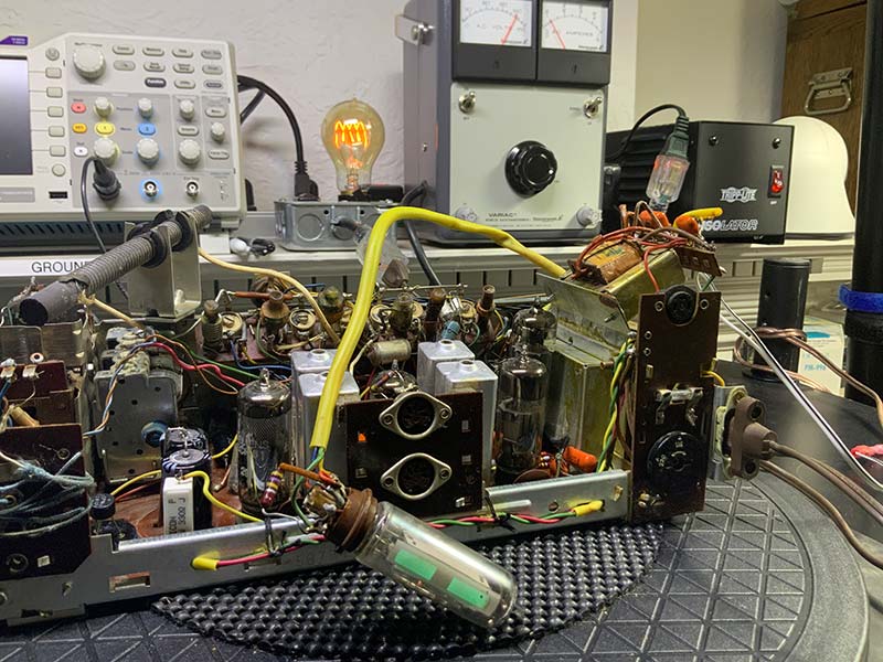
FIGURE 21. Initial power-limited testing. Note current limiter, variac, and isolation transformer in back.
After a 20 minute warm-up period, check the AM and FM functions separately. With the current limiter on, you’ll probably be able to pick up only the strongest signal on each band. Assuming an uneventful power-up, remove the current limiter from the circuit and apply full normal line voltage. Attach an FM antenna to the radio and try to pick up stations on each band. Are the signals strong and clean? Is there any hint of hum? How does the speaker sound? If you’re lucky, you may be able to skip the alignment step. More likely, however, is that your radio will require a little tweaking for the best reception.
ALIGNMENT
Alignment — if needed — is a straightforward process that’s defined in a full-page table on the schematic. As detailed in the instructions, you’ll need a stable signal generator to perform separate AM and FM alignments. As noted earlier, the Jubilate uses a 460 kHz IF on AM and 10.7 MHz IF on FM. Using the instructions in the schematic, set the signal generator to the specified frequency and modulation, and with the proper plastic tools, adjust the specified inductors in turn for maximum output. The alignment process requires about 10 minutes.
SPEAKER AND GRILL CLOTH
Although not necessary, I opted to replace the speaker and dirty grill cloth. If you decide to do the same, the first step is to remove the speaker board shown in Figure 22.
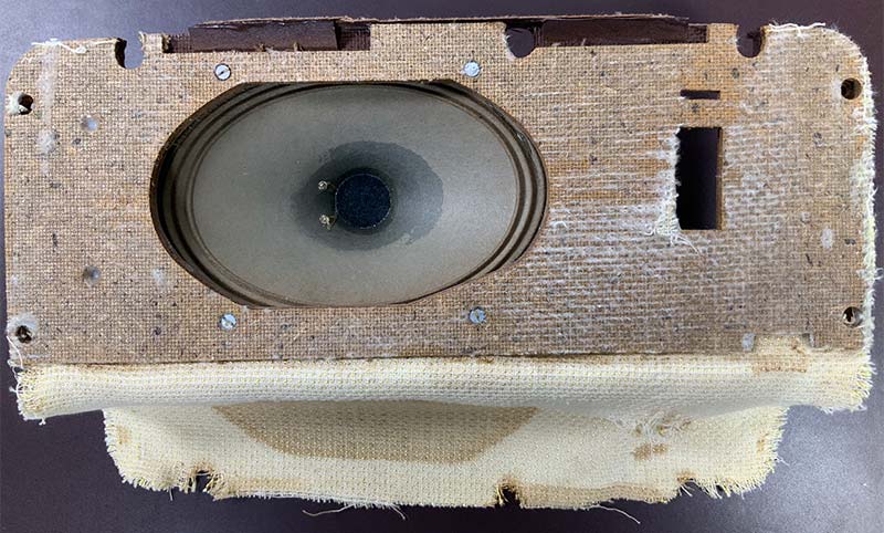
FIGURE 22. Speaker board with original 5x7 speaker and cloth cover removed.
Next, peel back the old cloth which is glued to the board. Replace the speaker and then glue on a new grill cloth using a spray adhesive. Figure 23 shows the bare speaker board ready for mounting the new speaker and new grill cloth.
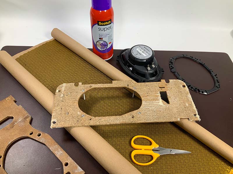
FIGURE 23. Preparing fittings for new speaker and gluing new grill cloth to speaker board.
Spray the adhesive on the board and not the cloth. Otherwise, you’ll muffle the sound from the speaker. Depending on the new speaker, you may have to reposition the mounting screws to accommodate new mounting holes.
BACK TOGETHER AGAIN
Carefully replace the glass front panel, mount the chassis in the wood enclosure, and connect the speaker to the output transformer, as in Figure 24.
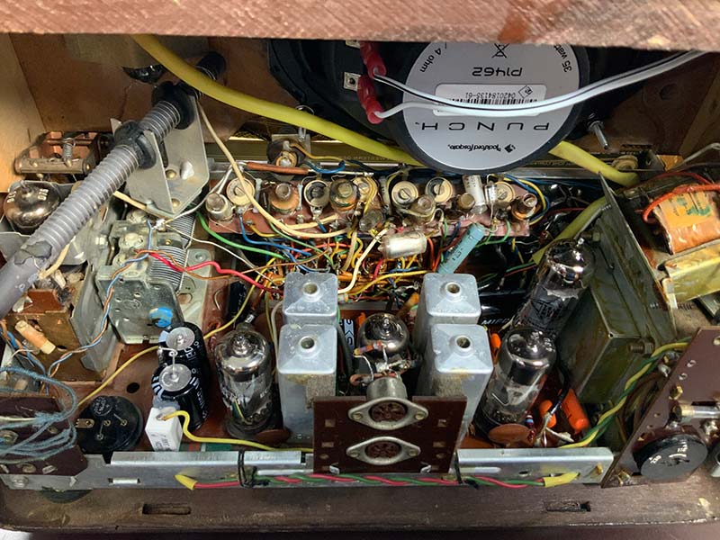
FIGURE 24. Refurbished circuit board and new speaker installed in case.
Next, lubricate the volume/tone pot shaft with a lightweight lubricant (Figure 25) before reinstalling the volume/tone and AM/FM frequency knobs (Figure 26).
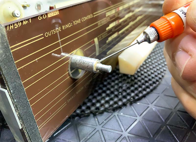
FIGURE 25. Lubricate the sleeve between the volume control and tone control.
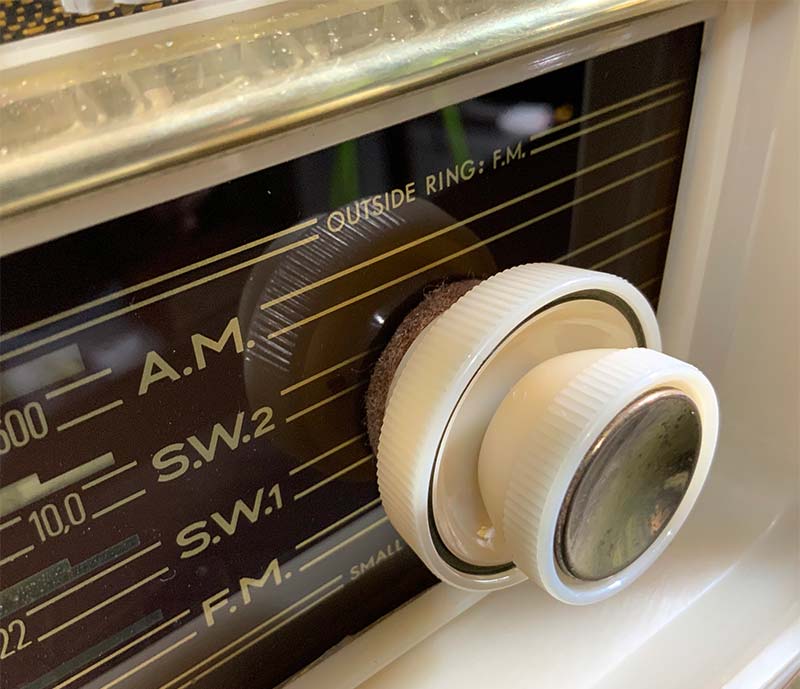
FIGURE 26. Close-up of refurbished knob and brass trim.
COSMETICS
Although I own an ultrasonic cleaner, I’ve had the best results cleaning knobs and other small parts with Super Clean and a soft toothbrush. Don’t get the Super Clean anywhere near a vacuum tube or the front panel because the chemicals will instantly remove any ink or paint from a glass surface. Of course, you can substitute a less aggressive cleaner for Super Clean.
To touch up the brass trim, I used Brasso™ and a fine steel wool pad after removing the trim from the plastic front panel. Remount the trim mounts with the original small brass pins and double-sided tape.
“Restoration” vs. “Preservation”
The focus of this restoration — as well as the others in this series — is to restore and, if possible, improve the functionality of the radios. This is in contrast with preservation, which would entail the use of New Old Stock (NOS) components and other original materials to preserve the original features of the radio.
Although my focus is on restoration, you are welcome to practice preservation. For example, I replace hot, inefficient, and short-lived panel lights with long-life LED equivalents whenever possible. You’re free, however, to use exact replacement bulbs.
Moving to the wooden case, I used fine steel wool to remove the original lacquer finish, taking care not to remove any of the thin, delicate wood veneer. Next, I used small amounts of mahogany colored wood putty to fill the pits and cracks in the veneer.
After removing dust from the surface with a microfiber cloth, I applied three coats of Minwax® clear satin lacquer, allowing each coat to dry in a well-ventilated but dust-free room. Although the lacquer is available as an easy-to-use spray, I’ve had better luck with the brush-on version. The result is shown in Figure 27.
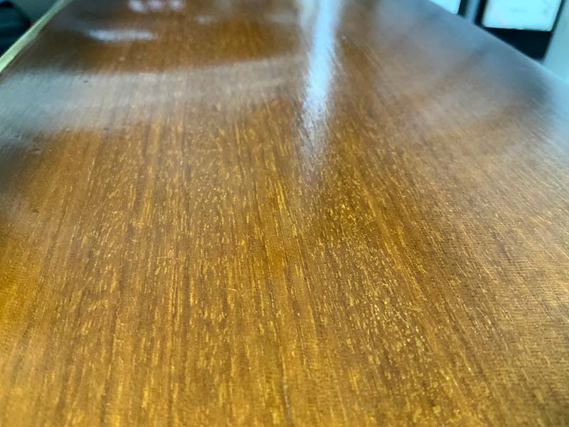
FIGURE 27. New wood finish free of cracks and pits.
Before you put the case away, verify that the felt pads are intact and protrude past the wood of the case. If the pads have flattened with time, replace them or you’ll risk scratching your tabletop or other soft surface.
END RESULT
As shown in the lead photograph, the Jubilate makes a smart retro addition to any bedroom or kitchen. The sound — especially in the FM mode — is rich and powerful enough to fill any room. This was a fun project, requiring about 20 hours of labor over several weekends. If you only need to replace the wax paper and electrolytic capacitors and power cord, expect to spend about $30. Tubes, a new speaker, paint, and any other components will add to the cost.
Figure 28 shows the refurbished radio undergoing burn-in on my workbench. I burn in my refurbished radios for at least 24 hours before I’m comfortable putting them into everyday service.
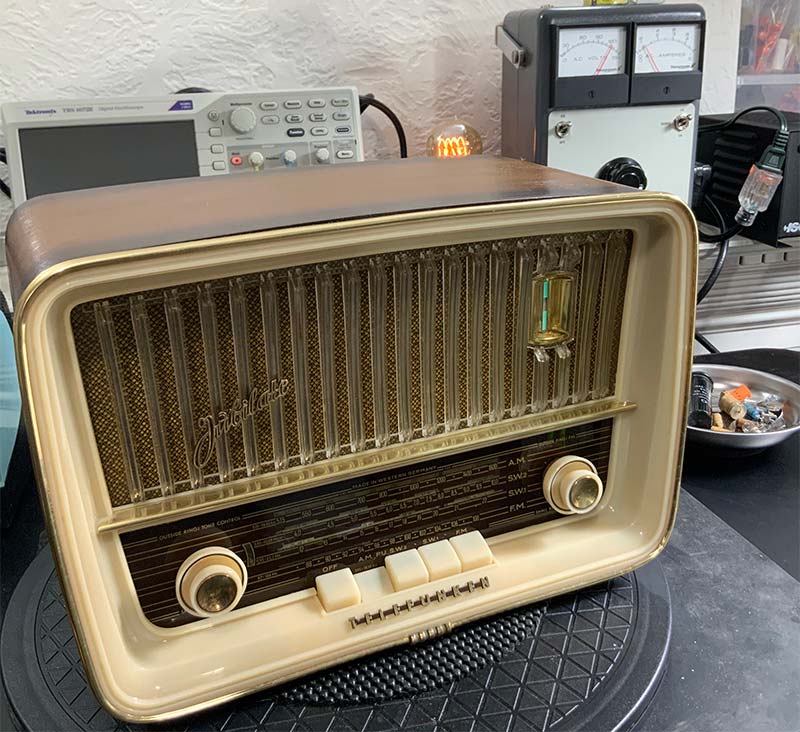
FIGURE 28. Refurbished unit undergoing burn-in on my workbench. Note active tuning light.
If a tube or new component is going to overheat and cause a problem, I’d rather have it fail on my workbench instead of on a nightstand in the middle of the night.
As you’ll see in upcoming projects with German and domestic radios in this series, once you learn one model from a given manufacturer, you learn them all. For example, every AM/FM Telefunken radio that I’ve worked on uses the same FM tuner assembly.
I’m sure you’ll discover other parallels as well. NV
Resources
Antique Electronic Supply (tubesandmore.com)
Handles just about everything, from metal can capacitors to schematics of vintage radios.
Hayseed Hamfest LLC (hayseedhamfest.com)
Custom replacement electrolytic can caps and kits for audio and ham electronics.
HiFiEngine.com
Manuals and schematics for vintage radios.
Radiomuseum.org
Summary photos and documentation on just about every radio receiver ever produced. A great starting point.
The Valve Museum (www.r-type.org)
Detailed specifications on just about any vacuum tube ever produced.
TubeDepot.com
My go-to source for vacuum tubes.
Turntableneedles.com
Good source for hard-to-find schematics.