Explore the world of tube-type electronics by restoring this domestic 1950’s AM/FM broadcast receiver: the Zenith G725.
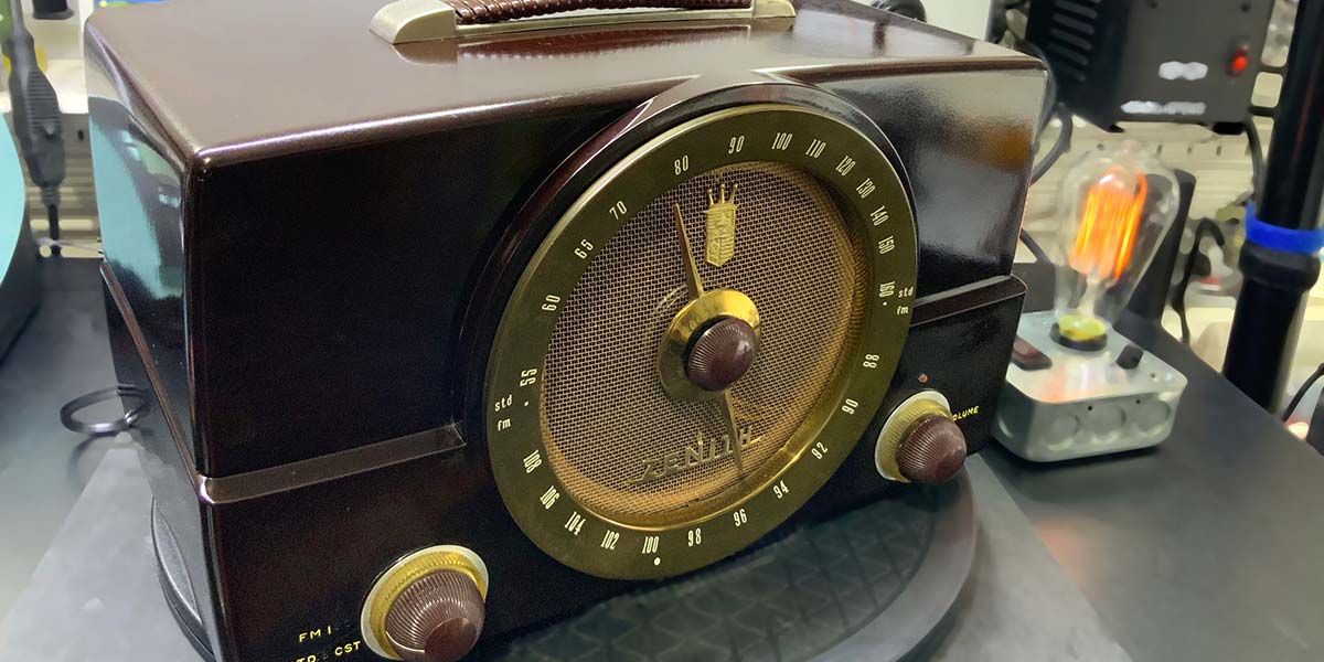
This article — a continuation of the series on the restoration of broadcast receivers — details the restoration of the Zenith G725: an AM/FM receiver introduced in 1950 (see Figure 1).
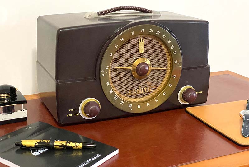
Figure 1. Restored Zenith G725 AM/FM receiver.
This radio makes a great first tube project because the plum Bakelite case is easily restored, the radio is affordable ($25 and up on eBay), and documentation is readily available. We’ll cover the restoration of Bakelite, replacing decomposed rubber insulators, updating a selenium-based power supply, measuring components in circuit, and recapping capacitors that are no longer produced. If you want to know more about domestic broadcast receivers, then check out the restoration of the Zenith H845/C845 (Nuts & Volts Issue-1 2020). For now, let’s jump into the specifics of the Zenith G725.
Zenith G725
The Zenith G725 was produced by Zenith Radio Corporation in Chicago, IL starting in 1950. The lunch kit sized radio measures 15x9x8 inches and weighs 9 lb 10 oz. The seven-tube receiver covers the domestic AM band (535-1605 kHz) and the US FM band (88-108 MHz). The Bakelite receiver has a forward-facing 7.5 inch moving coil speaker and an audio output of about 1.5 watts.
The seven-tube receiver follows the typical superheterodyne architectures for broadcast AM shown in Figure 2.
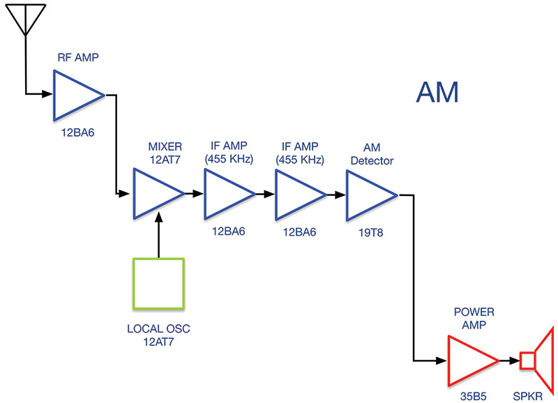
Figure 2. G725’s superheterodyne AM receiver architecture.
In the AM mode, the broadcast signal from the antenna is amplified and then mixed with the signal from the local oscillator. The standard 455 kHz intermediate frequency signal is selectively amplified, converted to audio by an AM detector (demodulated), and then amplified. There is no tuning indicator, but there is a small ON-OFF indicator light above the volume control. The tubes, their function(s) in AM and FM, and their least expensive TubeDepot.com price at the time of printing are listed in Table 1.
| Tube |
AM Function |
FM Function |
Price |
| 12BA6 |
RF Amp |
RF Amp |
$8.95 |
| 12AT7 |
Mixer/Oscillator |
Mixer/Oscillator |
$9.95 |
| 12BA6 |
First IF Amp |
First IF Amp |
$8.95 |
| 12BA6 |
Second IF Amp |
Second IF Amp |
$8.95 |
| 12AU6 |
|
FM Limiter |
$5.95 |
| 19T8 |
AM Detector |
FM Discriminator |
$7.95 |
| 35B5 |
1.5W Amp |
1.5W Amp |
$3.95 |
Table 1. Tubes, AM and FM functions, and the TubeDepot.com price.
In the FM mode, the broadcast signal from the antenna is amplified and converted to a 10.7 MHz intermediate frequency signal. Refer to Figure 3.
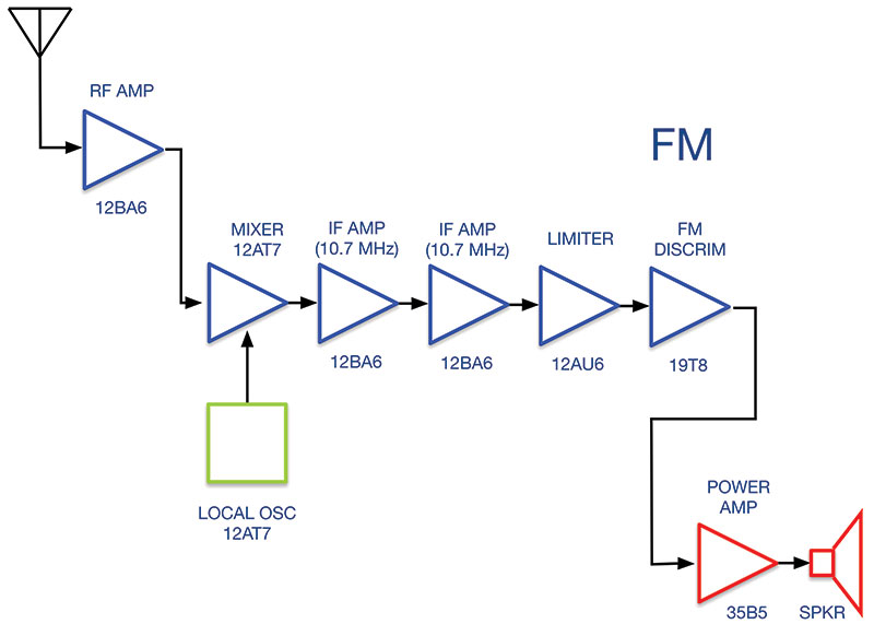
Figure 3. G725’s superheterodyne FM receiver architecture.
After two stages of IF amplification, the signal is then fed to the limiter. The output of the amplitude limiter is fed to an FM discriminator and then on to the 1.5W audio amplifier.
Refurbishing the Zenith G725 requires a detailed schematic as well as specific tuning instructions. You can download a free PDF of the full schematic along with tuning instructions from http://www.nostalgiaair.org/.
INSTRUMENTS
As with all the previous restoration projects in this series, at a minimum, you’ll need an isolation transformer, variable autotransformer, and a dim bulb current limiter.
If someone has played around with the tuning coils, then you’ll also need a vacuum tube voltmeter (VTVM) for voltage and resistance measurements. A DMM will also do, but a VTVM is best. If you intend to check capacitors in-situ instead of replacing every electrolytic, wax, and oil capacitor without testing, then you’ll need a capacitance meter. The capacitor function on many modern DMMs will be sufficient for this project.
Similarly, unless you’re lucky enough to have a radio with working tubes or happen to have a set of spares that you can swap in and out of the radio, you’ll need access to a tube tester. Finally, a smartphone or tablet with a digital camera is a must have. Photograph everything before you start and at each major step along the way. It just takes one misplaced capacitor to double the time required for recapping the radio.
THE RESTORATION
Let’s follow our usual restoration process (see the sidebar for a refresher).
External Inspection
Figures 4-9 show the external state of the G725 as I received it from an eBay seller ($26).
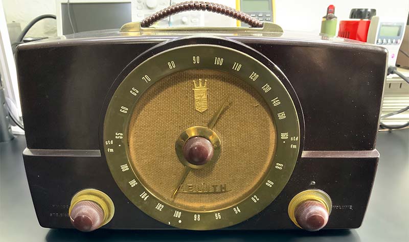
Figure 4. Front of unit, before restoration.
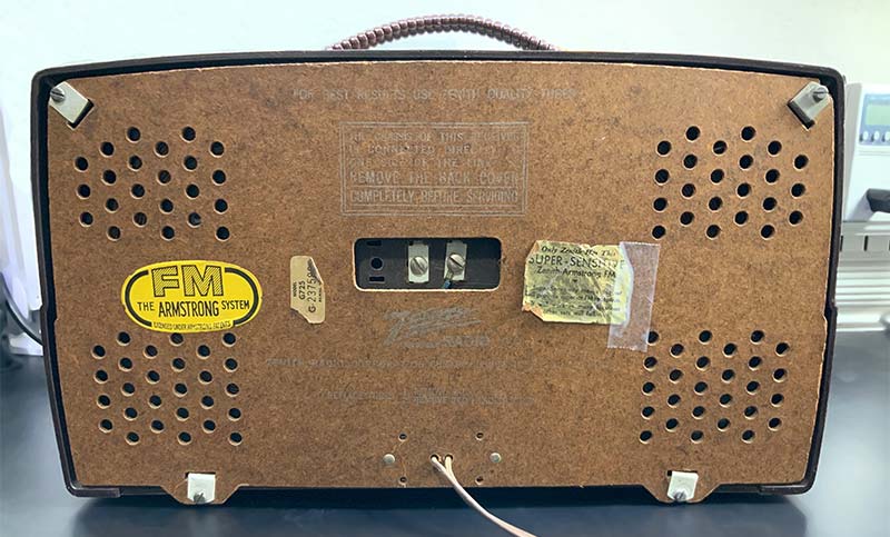
Figure 5. Back of unit showing no signs of water or other damage.
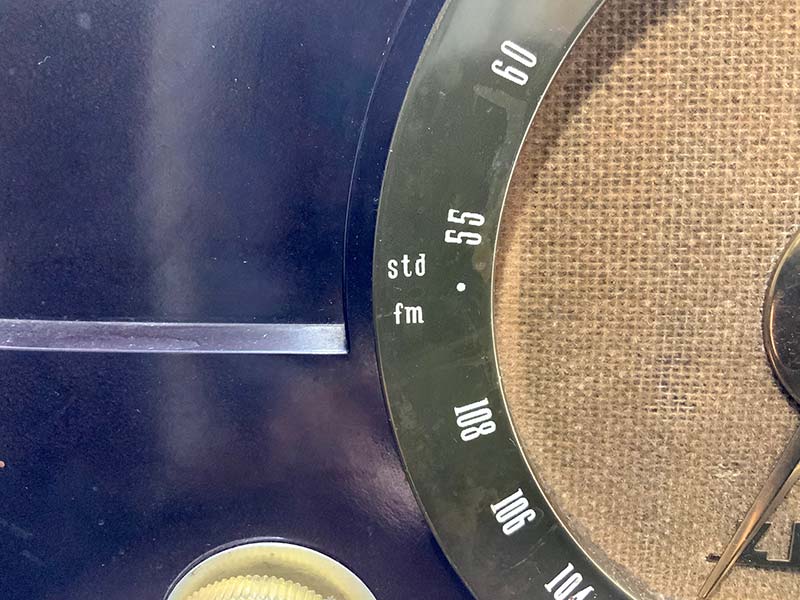
Figure 6. Close-up of tuning indicator and speaker grill.
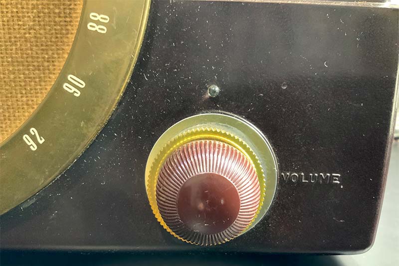
Figure 7. Pitted corner and volume control.
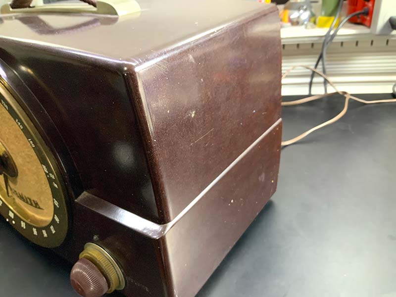
Figure 8. Side of unit.
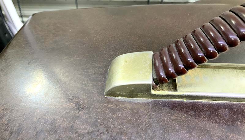
Figure 9. Top pitting and handle showing oxidation.
The plum-colored Bakelite was in excellent condition, with no major chips or cracks. There were numerous flecks and small pits, but nothing severe. The flocking on the wire mesh grill covering the 7.5 inch front-facing speaker was matted to the degree that it likely impeded higher frequency audio. The central tuning indicator/control had some excess play, suggesting the unit needed restringing.
The back of the radio (Figure 5) showed no sign of rain or other insult. A sticker clearly identified the unit as a G725. The vacuum tube placement chart on the underside of the radio — mainly intact (Figure 10) — identified the chassis type as 7G01.
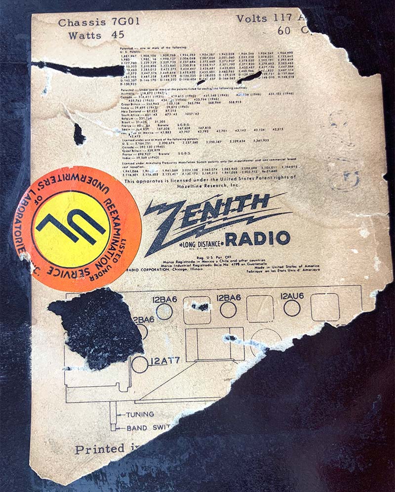
Figure 10. Tube placement chart and power requirements from bottom of unit.
Lastly, the two-prong, non-polarized power cord was surprisingly in excellent condition.
Internal Inspection
Internal inspection (Figures 11-17) is a straightforward process that starts with removing the front grill and knobs. As shown in Figure 11, it helps to have a pair of plastic pry bars to remove the dial/grill structure.
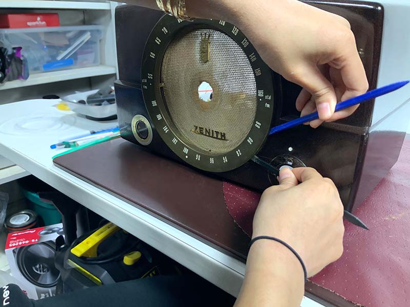
Figure 11. Removing front grill and knobs.
Set the grill and dial components aside (Figure 12) for cleaning. Note the use of cardboard spacers for the grill.
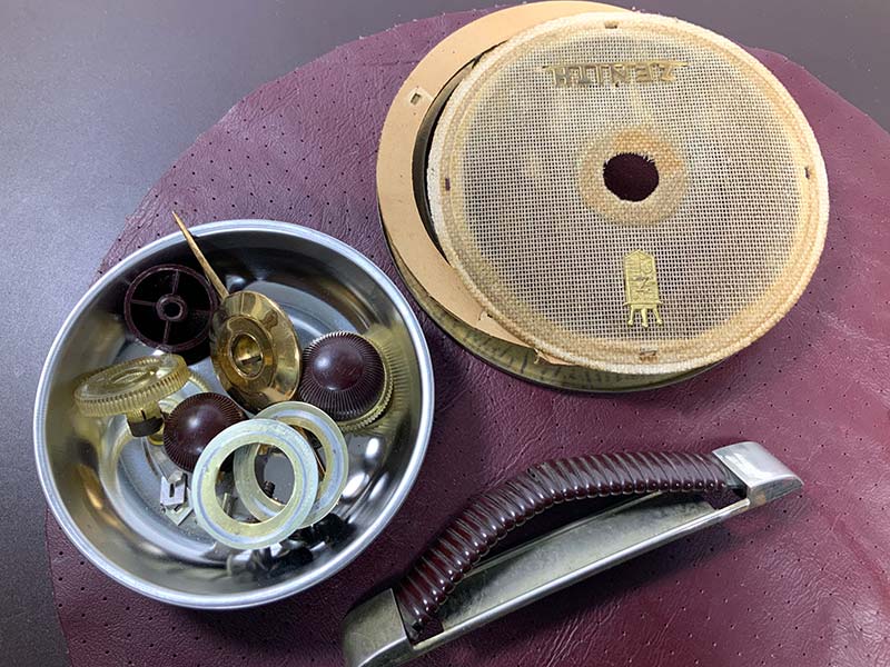
Figure 12. External components removed from Bakelite case.
Facing the front of the unit (Figure 13), note the condition of the speaker, the cord between the two frequency control knobs, and the general condition of the chassis. From Figure 13, note the naked spacer post on the far-left edge of the chassis.
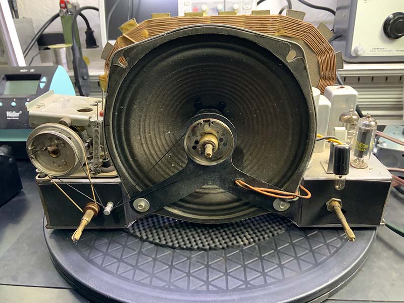
Figure 13. Front of unit, case removed, showing 7.5” speaker.
Also note the NE-2 lamp that indicates power on/off to the right of the speaker, just above the power switch/volume control. The back of the unit (Figure 14) shows an intact AM antenna loop that obscures most of the chassis.
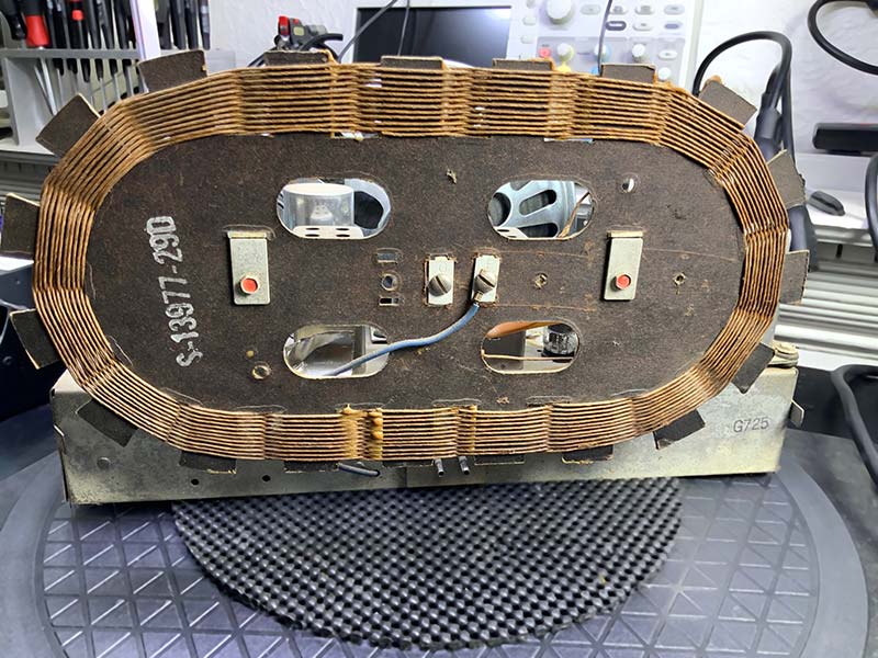
Figure 14. Rear of unit, case removed, showing AM antenna.
There are connections for ground (stamped “G”) and an external FM antenna (stamped “F”). Near the bottom center of the unit are the two male prongs for 115 VAC. Note there are no fuses.
The top of the unit (Figure 15) shows the seven vacuum tubes, roughly aligned with the signal path from left to right, starting with the 12BA6 RF amp at the lower left of the chassis and the 35B5 audio amp at the lower right of the chassis.
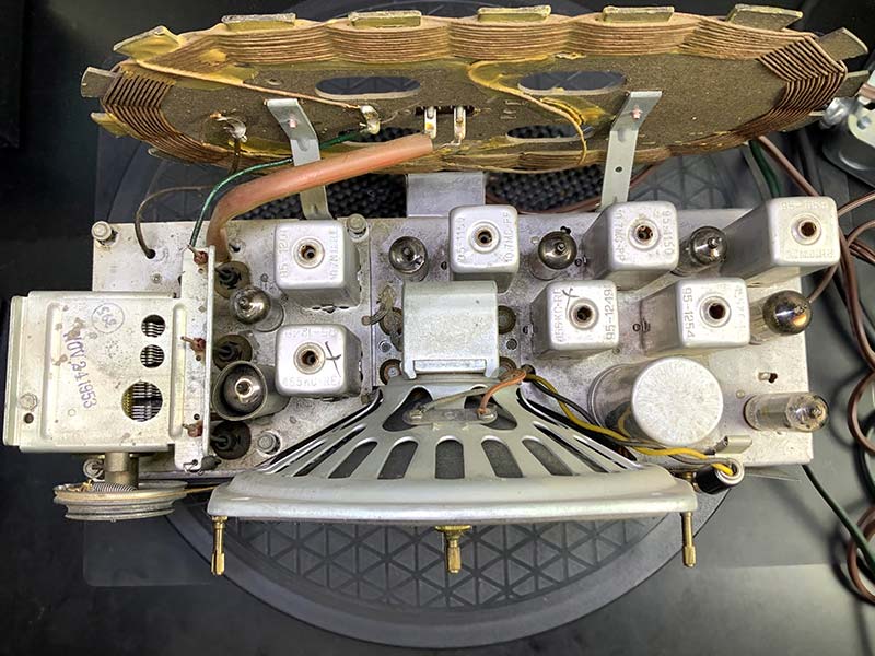
Figure 15. Top of unit, case removed, showing tubes and filters.
The single canned filter capacitor is just behind the speaker, adjacent to the 35B5.
The bottom or component side of the unit (Figure 16) is covered by a steel cap attached with two metal screws on either side of the radio.
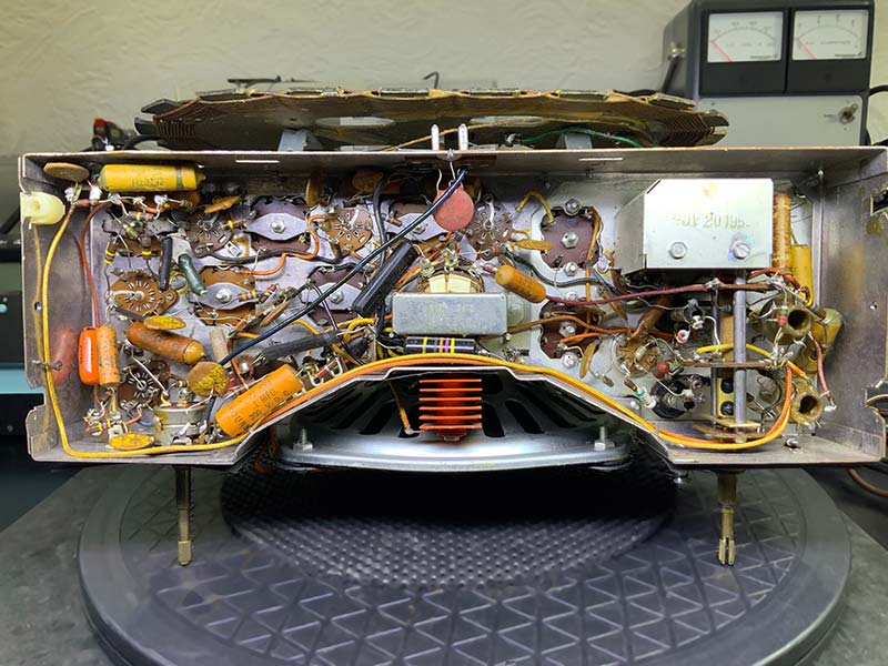
Figure 16. Underside of unit, bottom cover removed, showing components.
Removal of the cap reveals clean point-to-point wiring with almost no dust or sticky residue. About two dozen wax paper capacitors are visible, all of which will be replaced. Note the date stamped on the chassis: Nov 20, 1953. The bright orange selenium rectifier is dead center, just behind and below the speaker. A large, black, oil-filled bumblebee capacitor can be seen immediately opposite the rectifier.
Note that because the bottom metal cover is a tight fit, it’s often not replaced. I’ve had several Zenith radios with the same or similar chassis that arrived without the metal cover. This is a problem because shielding is incomplete, and the circuitry is more susceptible to interference.
The large variable air capacitor is mounted on the left side of the radio. As shown in Figure 17, the plates on the capacitor are clean, parallel, and not touching the adjacent opposite plates.
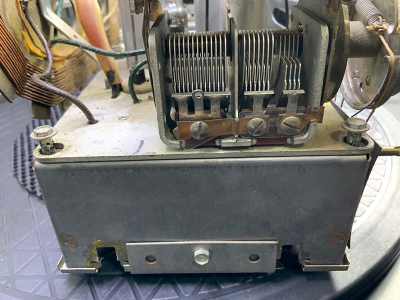
Figure 17. Side of unit, showing tuning capacitor and missing grommets.
The mica dielectric on one of the trimmer capacitors is out of alignment — an easy fix.
The biggest problem revealed in Figure 17 is the missing grommets on the front and rear corners of the chassis. Both the plate currently resting directly on the chassis and the chassis are equipotential at DC because the plate is attached to the chassis toward the middle of the unit by a length of flexible braid. At RF, the plate and underlying chassis are not of equipotential. This design apparently avoids ground loops.
Similarly, the four grommets insulating the speaker mount from the main chassis had disintegrated. Whatever the engineering intent, without the insulating grommets in place, the radio does not work correctly.
Cleanup
Cleanup is normally a time-consuming process involving multiple cleaners, compressed air, and lots of elbow grease. That was not the case here. I used some compressed air and cleaned the top of the radio. No other cleaning was required.
Power Supply Upgrade
The power supply upgrade for this radio is a simple silicon-selenium swap with the addition of a series resistor to make up for the lower voltage drop across a silicon diode. See Figures 18 and 19.
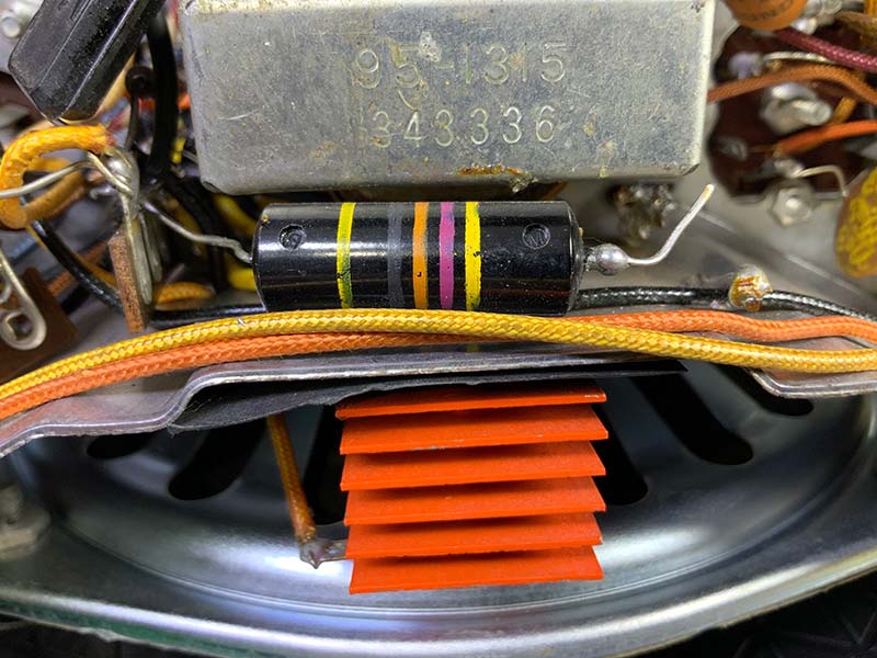
Figure 18. Selenium rectifier (orange plates).
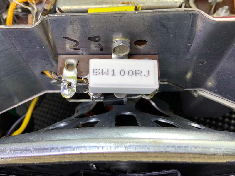
Figure 19. Replacement silicon diode and series resistor.
The bright orange selenium rectifier is bolted to the chassis with a single sheet metal screw.
Remove the screw and use it to mount a four-pin terminal strip. Mount an IN4007 diode (1KV at 1A) and a 100 ohm at 5W series resistor on the strip and connect the AC in and DC out wires. Based on my tests, the voltage drop across the 100 ohm resistor is just enough to make up for the increased efficiency of the silicon diode.
Recapping
Recapping and, potentially, swapping new resistors for old is facilitated by the point-to-point wiring of relatively large components. No SMT tweezers or magnifying glasses required here. As you know, my approach to recapping is all-out war. I replace everything electrolytic and wax/paper with new poly caps with very conservative voltage ratings. For example, as soon as I purchased this radio, I ordered a replacement can electrolytic capacitor from Hayseed Hamfest — my go-to for old and new canned electrolytics.
In this older radio, you may be surprised by oddly shaped components, such as the rectangular resistor shown in Figure 20.
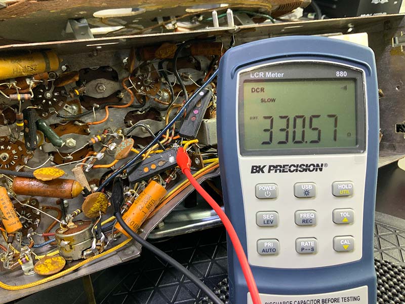
Figure 20. Testing a rectangular resistor in-situ.
In-situ testing with a VTVM, DMM, or (preferably) a dedicated component tester such as the BK Precision LCR meter can verify component type and value. Figure 20 shows a 330 ohm (orange, orange, brown) resistor. From the size, I believe it’s a 5W resistor.
Figure 21 shows the in-situ testing of the (physically) large bumblebee capacitor.
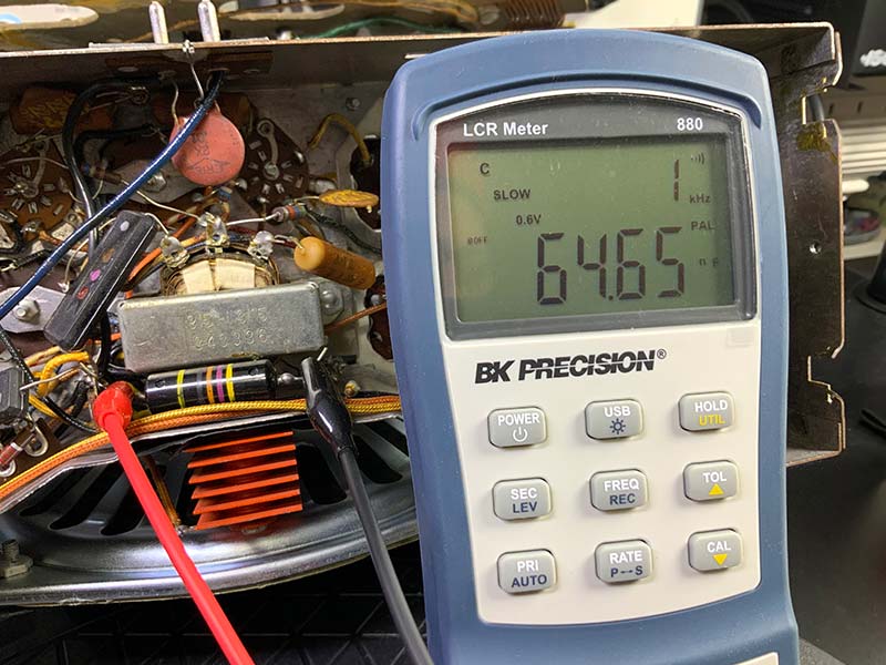
Figure 21. Testing an oil capacitor in-situ.
The outside foil lead (the lead on the right with the solder bulb) is lifted for the measurement. Note the discrepancy between the expected value of the capacitor, .047 µF (yellow, violet, orange, black, yellow), and the measured value of 64.55 nF or .065 µF. Figure 22 shows one of the surprises in this radio: a three-lead wax capacitor.
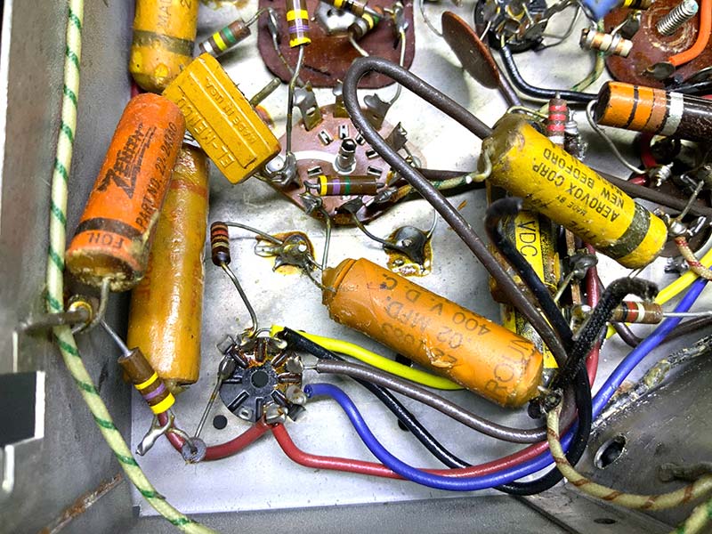
Figure 22. Three-lead capacitor.
The outer lead of the capacitor is a grounded shield. I made a replacement capacitor by winding a coil of bare copper wire around a poly capacitor (Figure 23) and encasing the capacitor in clear shrink wrap (Figure 24).
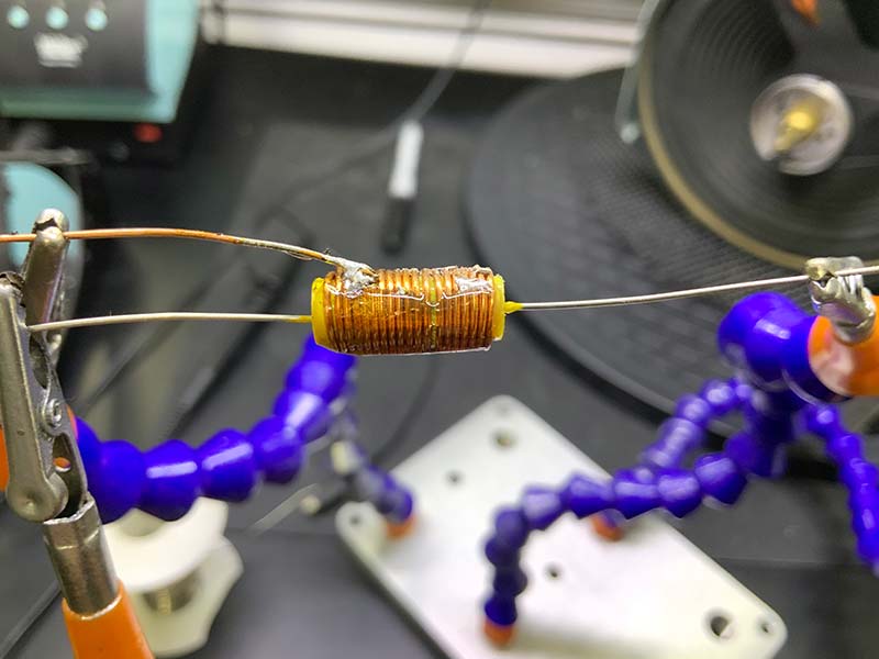
Figure 23. Winding new capacitor.
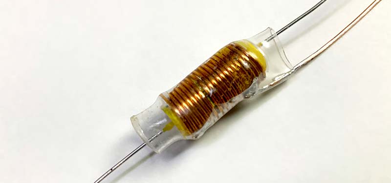
Figure 24. New three-lead capacitor ready for installation.
Switch and Potentiometer Cleaning
I cleaned the potentiometers and switches with a few liberal squirts of CRC QD Electronic Cleaner. Because the cleaner doesn’t provide any long-term protection against oxidation, I followed up several hours later with a very small amount of DeOxit. Because DeOxit becomes gummy and attracts dust over time, avoid overspray onto the chassis or other components.
Chassis Repair
I replaced the four silicone grommets between the speaker and chassis (Figure 25) and the four silicone grommets between the floating plate with the tuning capacitor (Figure 26).
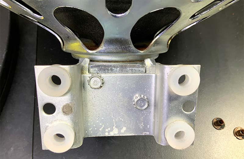
Figure 25. Speaker with replacement silicone grommets.
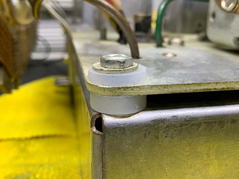
Figure 26. Chassis with replacement silicone grommets.
Next, I replaced the cord connecting the variable air capacitor shaft connected to the outer ring of the potentiometer on the left with the frequency indicator at the center of the speaker.
Refer to Figures 27-29. Make certain you use cord advertised for radio repair. It has just the right mix of elasticity and friction.
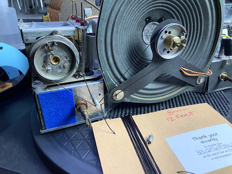
Figure 27. Restringing central control.
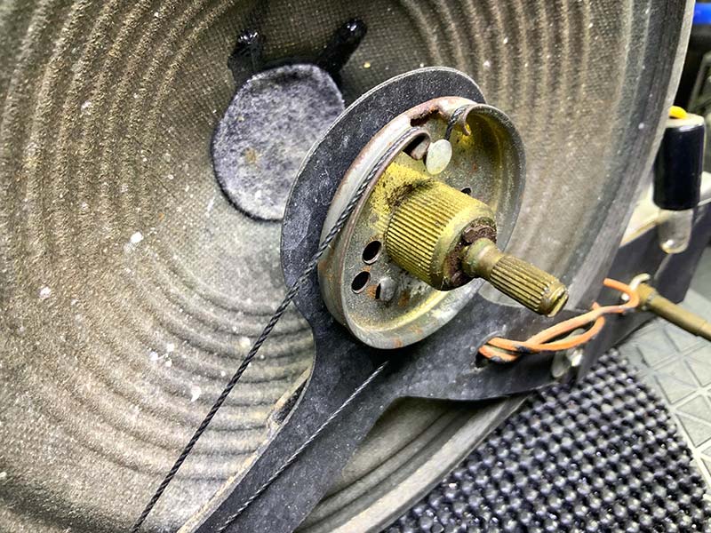
Figure 28. Central control close-up.
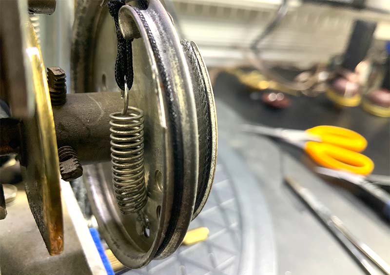
Figure 29. Capacitor control close-up.
Resistance Check
Given the simplicity of the circuit, I performed a cursory resistance check. I checked the resistance across the power input, across the high voltage to ground, and across the electrolytic capacitors and ground. I didn’t find any faults.
Power-On
If you’ve been following this series, the initial power-limited testing with an isolation transformer, a Variac, or another variable AC voltage transformer and dim bulb current limiter should be second nature. Assuming an uneventful limited power-up, remove the current limiter from the circuit and apply full normal line voltage. Attach an FM antenna to the radio and try to pick up stations on each band. Are the signals strong and clean? Is there any hint of hum? How does the speaker sound?
If you’re lucky, you may be able to skip the alignment step. More likely, however, is that your radio will require a little tweaking for the best reception.
ALIGNMENT
Alignment (if needed) is a straightforward process that’s defined in a full-page table on the schematic. As detailed in the instructions, you’ll need a stable signal generator to perform separate AM and FM alignments. This Zenith radio uses a standard 455 kHz IF on AM and 10.7 MHz IF on FM.
Using the instructions in the schematic, set the signal generator to the specified frequency and modulation and — with the proper plastic tools — adjust the specified inductors in turn for maximum output.
The major challenge aligning this radio, compared with the later Zenith models, is that FM slugs were fixed with some sort of cement.
As per the instructions on the schematics, I had to use a hot soldering iron to loosen the cement. The AM slugs had no such treatment.
COSMETICS
Bakelite is a joy to work with. To bring back the original finish, I used a pad of super-fine steel wool and a good amount of Brasso to both remove a layer of Bakelite and polish the newly exposed Bakelite. After about 10 minutes of vigorous polishing, I washed the case in warm water and Dove liquid. I used the same Brasso and a fresh fine steel wool pad to polish the brass trim before returning the speaker grill and tuning indicator to the Bakelite case.
Bakelite
Bakelite, invented over a century ago, was the first synthetic plastic made entirely from synthetic components. Because it didn’t rely on natural materials such as rubber latex (rubber), plant cellulose (Celluloid), or milk protein (Galalith), it was inexpensive, and production was independent on the output of farms. Resistance to heat and electricity made it perfect for electrical appliances such as tabletop radios, telephones, clocks, and lamps. The glossy finish and feel made it attractive for consumer jewelry applications.
Lastly, I recruited the help of an artist to apply yellow enamel paint to the very slightly raised labels above the left and right knobs on the receiver. The lines used to form letters are the width of a toothpick, requiring a high level of small muscle coordination. Refer to Figure 30.
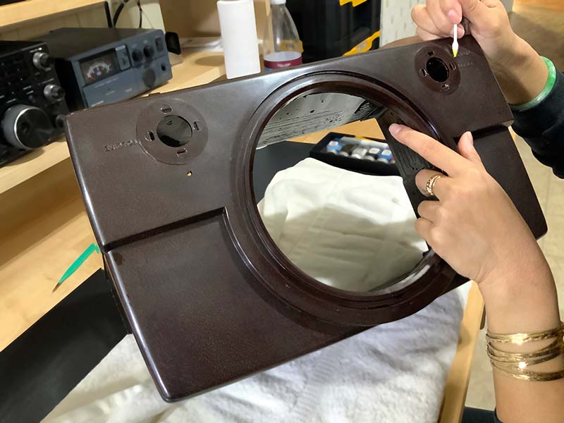
Figure 30. Bakelite case at final stage of refinishing.
BACK TOGETHER AGAIN
Reassembly involves sliding the chassis into the Bakelite case, attaching the potentiometer knobs, and securing the bottom of the unit to the case. Figure 31 shows the fully assembled radio on my workbench during the 24 hour burn-in.
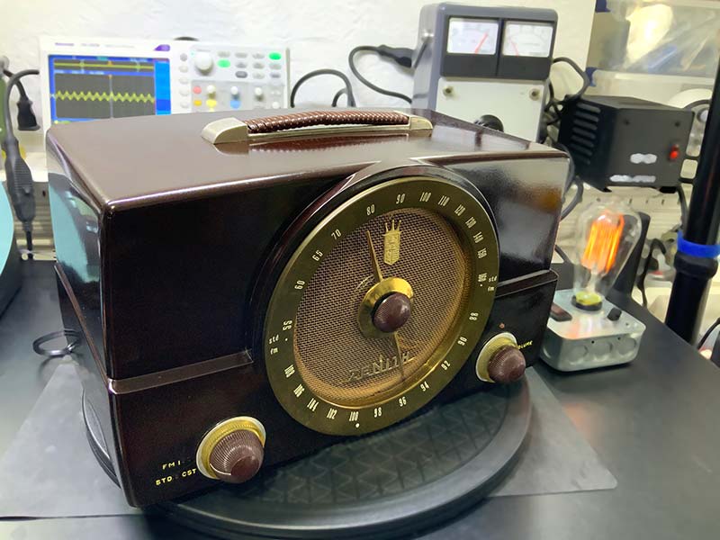
Figure 31. Reassembled radio during burn-in.
Figure 32 shows a close-up of the cosmetic work.
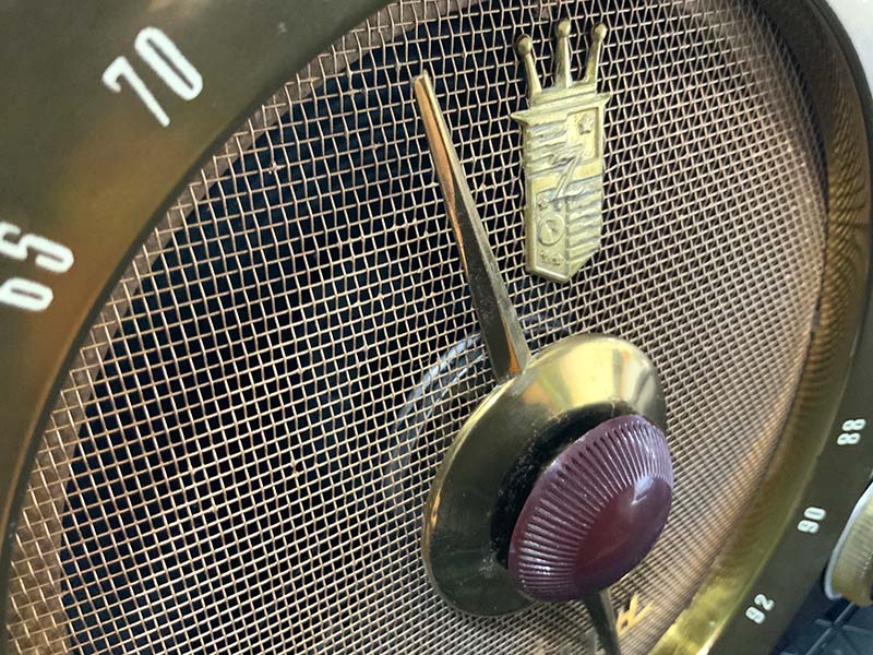
Figure 32. Close-up of grill, central control, and dial.
END RESULT
In all, restoring the G725 was an enjoyable way to spend the weekend, with help on the artistic end.
What’s more, the deep plum Bakelite is a conversation piece just sitting there. NV
The Restoration Process
As a reminder, the restoration process that I’ve advocated throughout this series is, in order:
- External Inspection
- Internal Inspection
- Cleanup
- Component Selection
- Power Supply Upgrade
- Recapping
- Potentiometer Cleaning
- Display Upgrade
- Resistance Check
- Power-On Check
- Adjustment
- Reassembly
- Burn-in
RESOURCES
Antique Electronic Supply (tubesandmore.com)
Handles just about everything, from metal can capacitors to schematics of vintage radios.
Hayseed Hamfest LLC (hayseedhamfest.com)
Custom replacement electrolytic can caps and kits for audio and ham electronics.
HiFiEngine.com
Manuals and schematics for vintage radios.
Radiomuseum.org
Summary photos and documentation on just about every radio receiver ever produced. A great starting point.
The Valve Museum (www.r-type.org)
Detailed specification on just about any vacuum tube ever produced.
TubeDepot.com - My go-to source for vacuum tubes.
Turntableneedles.com
Good source for hard-to-find schematics.