Explore the world of tube electronics by following along with the restoration of this classic US made preamp from 1965.
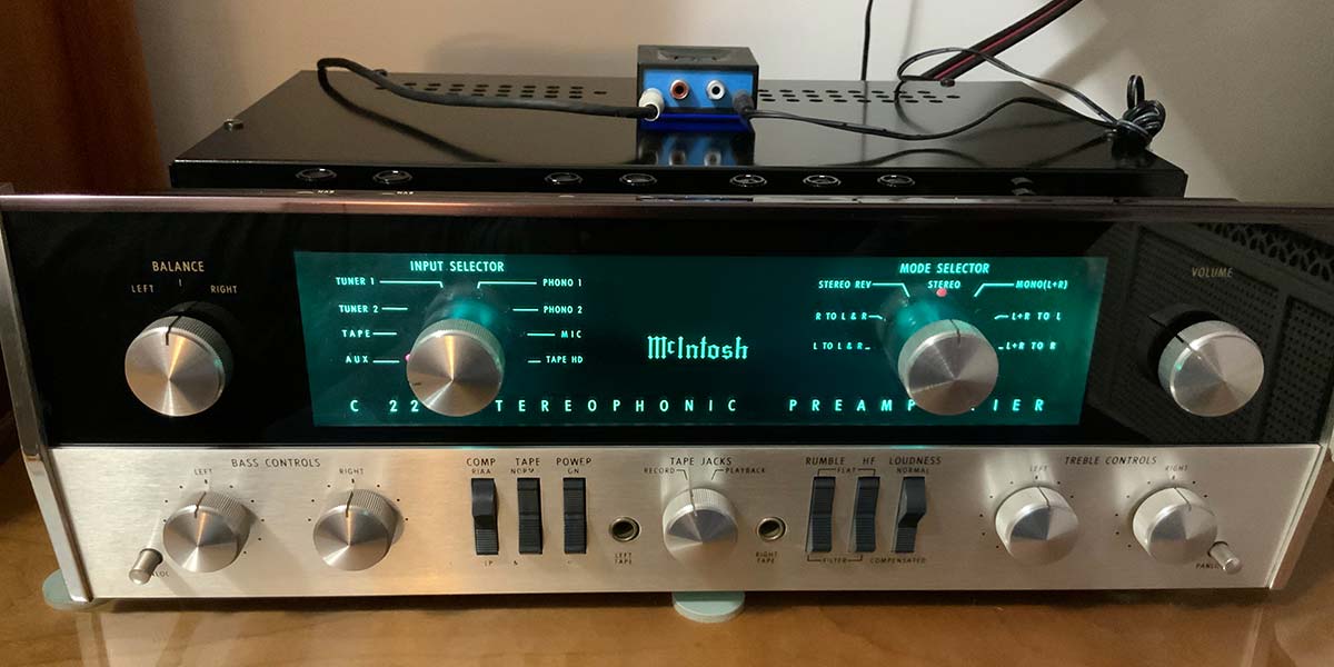
The focus of this third article in our series that explores vintage tube technology is the restoration of the McIntosh C22 tube preamplifier, shown fully restored in a custom walnut case in Figure 1. The C22 — one of my holy grail audio electronics acquisitions — is known for quality in engineering and construction and audiophile performance. The C22, which originally sold for $330 in 1965, now sells for between $3,000 and $6,000, depending on condition. Even if you don’t own a C22, by following along, you can pick up pointers for your own vintage restoration project — especially when it comes to restoring improperly serviced gear.
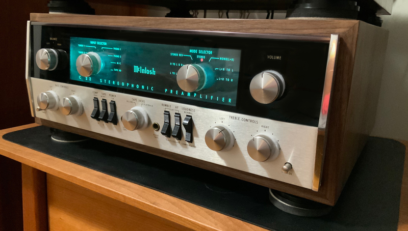
FIGURE 1. Restored McIntosh C22 preamp.
McIntosh Audio Equipment
McIntosh audio equipment from McIntosh Laboratory, Inc., Binghamton, NY, is probably the best known audiophile-grade gear ever designed and manufactured in the US. The company, founded in 1949, is still going strong, with solid-state and tube offerings for stereo and home theater applications. It’s easy to find a schematic — and the all-important service bulletins — of just about any McIntosh audio product ever released, either from official sources or any number of McIntosh-specific sites on the web.
Unlike the self-contained tabletop radios covered previously in this series, the C22 is part of a component system that enables the user to cherry pick each part. For example, my stereo system includes a McIntosh R71 receiver, a McIntosh 240 stereo power amplifier, a modern Thorens TD 309 turntable, the C22, and a pair of Polk tower speakers. The preamp provides impedance matching, filtering, and amplification of signals from the turntable, receiver, and other sources, and presents them to the power amplifier and speakers.
In theory, a component stereo system provides the best of each audio technology. In practice, I can’t tell the difference between my system and a McIntosh all-tube integrated receiver/amplifier. Similarly, specification-wise, contemporary solid-state systems provide much more power at less total harmonic distortion at a much lower price point.
That said, if, like me, you prefer a warm tube sound and the presence of a large stereo system over the cold accuracy of a miniature solid-state stereo system, then you’ll love the C22. And, as an added bonus, the C22, like other tube-type McIntosh products, is a breeze to restore.
McIntosh C22 Preamp
The McIntosh C22 preamp, introduced in 1963 for $279, enjoyed a production run of five years. The sturdy 15” x 5” x 13” (WxHxD) steel chassis weighs 16 lbs. The optional wooden case adds another 1.5 inches to each dimension.
The back panel is packed with RCA connectors for input and output, and there are two input ports in the front panel, for a total of eight stereo channels.
The channels are: Auxiliary; Phono 1 and 2; Tuner 1 and 2; Microphone; Tape Head; and Tape Capture. The overall frequency response of the C22 is 20 Hz–20 kHz ±0.5 db, and the six 12AX7s and four incandescent indicator lights draw about 0.3A at 115 VAC.
The basic architecture of each channel in the stereo C22 is shown in Figure 2.
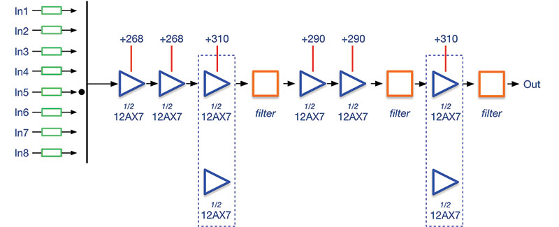
FIGURE 2. McIntosh C22 basic architecture (one channel).
Each of the six amplifier stages (blue) is comprised of half of a dual triode 12AX7 or equivalent ECC83S. As shown in the figure, each input provides an impedance matching resistor or resistors (green), and one of the eight inputs is presented to the first of three 1/2 12AX7s. The three amplifiers lead to an R-C filter (orange), then to a pair of amplifiers, a second filter, a final amplifier, and a final filter. The output is presented to the power amplifier.
Note that the first two amplifiers in a channel are in a single tube (that is, share the same glass envelope), whereas the third amplifiers share a glass envelope with a triode amplifier used by the opposite channel.
Similarly, the fourth and fifth amplifiers in each stereo channel share a glass envelope. The last stage of amplification (like the third stage) shares a glass envelope with an amplifier of the opposite channel.
Note also the B+ supplied to each triode amplifier. The first two amplifiers are supplied with 268 VDC. The third and sixth amplifiers are supplied with 310 VDC, and the fourth and fifth amplifiers are supplied with 290 VDC. These supply voltages will become more important in the discussion that follows.
Figure 3 shows the basic configuration of tandem triode audio amplifiers used in the C22 and many other preamplifiers. The input signal is fed to the grid of the first amplifier; one of the two triodes in a 12AX7. The output of that triode amplifier is fed through a coupling capacitor (in this example, C1) to the grid of the second triode. The output is sent through a second coupling capacitor (C2, Figure 3) to either the grid of a third amplifier or the input of a filter.
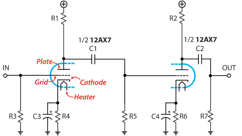
FIGURE 3. Basic 12AX7/ECC83S audio amplifier configuration.
Amplifiers that share a common glass envelope tend to share electrical characteristics, at least more than two separate random tubes do. That is, they tend to be matched — a highly desirable trait in a stereo preamplifier.
My C22 was populated with six new JJ ECC83S tubes. These are good quality tubes, available for about $20 each on TubeDepot.com. Some audiophiles might scoff at the thought of spending such a pittance on the only tubes in the device and opt for something like the Telefunken Smooth Plate/Diamond Bottom 12AX7/ECC83S, available for $600 each on TubeDepot.com. For my current budget, the $20 tubes are adequate.
Filtering is provided by 18 R-C filters in the form of thin, rectangular multi-pin devices. The filter functions include:
- High Frequency, 5 kHz Cutoff
- RIAA/LP Record Equalization
- Rumble, 50 Hz Cutoff
- Bass, 20 Hz
- Treble Boost, 20 kHz
- Treble Cut, 20 kHz
Starting in 1965, the flat orange R-C filter modules were produced by Sprague, as is the case in my unit. That is, if you’re into dating your C22, units produced in 1963 and 1964 have non-Sprague filters.
THE RESTORATION PROCESS
The restoration process for the C22 is generally the same as that used in the previous two desktop radio projects:
- External Inspection
- Internal Inspection
- Cleanup
- Component Selection
- Power Supply Upgrade
- Recapping
- Potentiometer Cleaning
- Display Upgrade
- Ohmmeter Check
- Power On Check
- Adjustment
- Reassembly
- Burn-In
The exception in this case (described in detail below) is that I powered up the unit after a cursory external inspection.
DOCUMENTATION
A download of the C22 schematic, owner’s manual, as well as the all-important service bulletins are available for free from hifiengine.com. You do have to register for a free account.
The service bulletins cover topics such as how to upgrade from selenium to silicon rectifiers and how to change indicator bulbs. Alternatively, you can download the schematic only from tubebooks.org, which does not require registration.
INSTRUMENTS
My goal in restoring the C22 was to verify each channel was operational and to remove components that were likely to fail in the near future. For this task, I used an isolation transformer, a Variac™ variable autotransformer, a dim bulb current limiter, a Fluke 87V DMM, and the camera on my iPhone.
If your goal is to bring a C22 or other preamp up to original specifications, then you’ll need a power meter, total harmonic distortion (THD) meter, a clean (preferably analog) signal generator, and an oscilloscope.
RESTORATION
The seller of the C22 on eBay assured me that the unit was working, provided photographs of the super-clean unit powered up and connected to an extensive component system, and had a perfect eBay rating. As such, my initial plan was to recap the unit, upgrade the power supply, and replace the short-lived incandescent bulbs with LEDs. Unfortunately, the actual restoration process didn’t progress as planned.
External Inspection
Figures 4 and 5 show the external state of the C22 as I received it from eBay. Except for a small chip in the front panel and some worn text on the controls, the unit looked almost like new. Even the two-pronged, non-polarized power cord was in excellent condition.
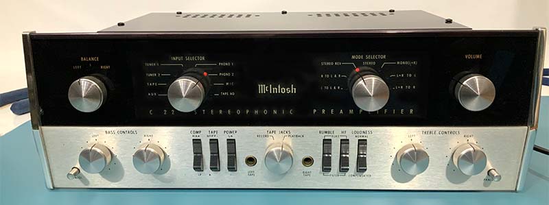
FIGURE 4. Front of C22, showing minor cosmetic defects.
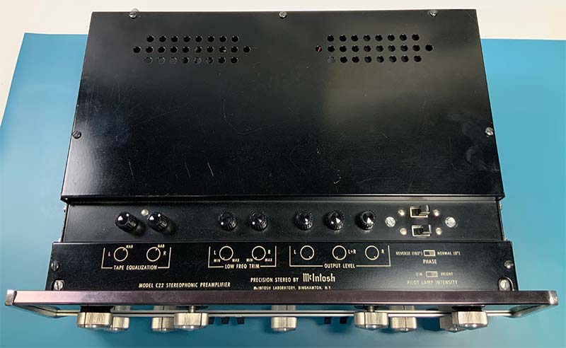
FIGURE 5. Top of C22, showing user controls.
Within minutes of unboxing, I plugged the C22 into the power mains and wired it into my component stereo system. The only problem obvious from the front of the unit (shown in Figure 4) was that the bulbs illuminating on either side of the glass front panel were out. The top (shown in Figure 5) revealed only shallow scratches.
All the switches and knobs appeared to work properly and crisply. I tried the C22 on audio from my iPhone and the Phono input from my turntable. The sound was good in both cases.
Internal Inspection
I began the internal inspection by removing the bottom cover, revealing the six tubes, the power supply, the majority of the resistors, and most of the filter devices (see Figures 6-9). As you can see, the layout is elegant and spacious. Virtually every component is clearly visible; approachable via test probes and soldering irons. Note the orange Sprague filters soldered to the front panel rotary switches (bottom, Figure 6).
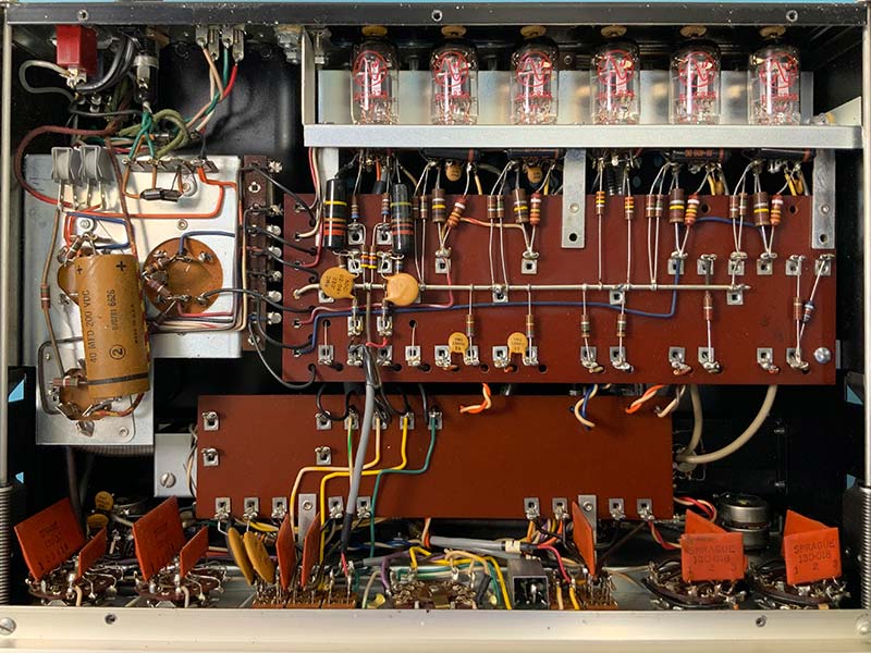
FIGURE 6. Component view with bottom plate removed.
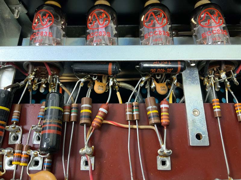
FIGURE 7. Tube base close-up showing capacitors tucked next to each tube.
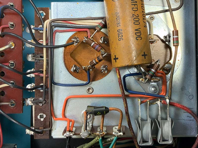
FIGURE 8. Power supply module with HV selenium diode bridge in lower right.
A totally unexpected finding — given that the unit was working — was a scorched (i.e., carbonized) terminal strip and associated wiring on the power supply module, as seen in Figure 9.
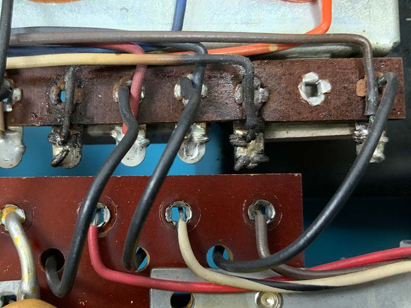
FIGURE 9. Scorched power supply terminal strip close-up, from underside of C22.
The scorched power supply output terminal strip was also visible from the top of the unit, as in Figures 10 and 11.
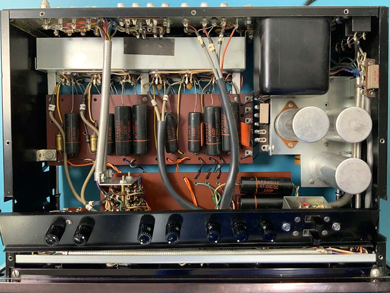
FIGURE 10. Internal view, top cover removed.
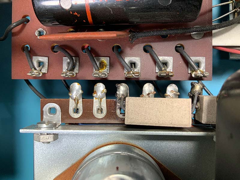
FIGURE 11. Scorched power supply terminal strip close-up, barely visible behind tan 5W resistor, as viewed from the top.
The wiring connected to the charred terminals looked original in terms of color, insulation, and gauge. Although there was soot and other signs of a fire, there were no loose wires, bolts, or other free-floating conductors.
My working hypothesis was that — given the power supply terminals are only a few mm from the terminals on the adjacent board — the chassis had flexed and shorted out the high voltage output. A technician might have picked up the unit, plugged into the AC mains, and allowed the unit to twist and the contacts to touch. In any event, I made note of the damage: wires, a terminal strip, and two 5W power resistors.
As the last part of the inspection, I used my eTracer vacuum tube checker to check each of the six vacuum tubes. All tubes passed the basic test for amplification factor (mu) and lack of shorts. I also checked for a balanced final output tube as in Figure 12.
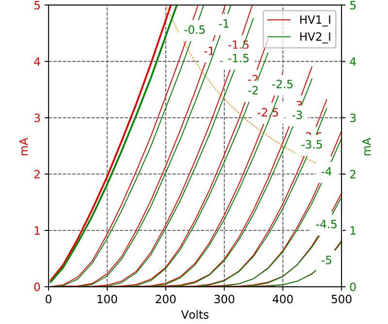
FIGURE 12. Overlaid grid voltage curves for plate voltage vs. plate current for final stage triodes (V6A red and V6B green) from eTracer, showing a very good match.
The two triodes in the sixth and final tube are nearly identical, as shown by the nearly overlapping plate voltage/current tracings. The family of curves is created by measuring the plate current with increasing plate voltage with a fixed grid bias. For example, with a grid voltage of -1V (third pair of tracings from the left), the plate current for each triode is about 2 mA at a plate voltage of 200 VDC. The closer the overlap of the tracings from each triode, the closer they are in electrical performance.
Cleanup
Cleanup with the C22 was a breeze and limited to addressing the normal aging of components. For example, I had to replace the deteriorated foam on the front panel rocker switches shown in Figure 13. Although the foam had no electrical consequences, the feel of the switch was much smoother and quieter with new foam backing.
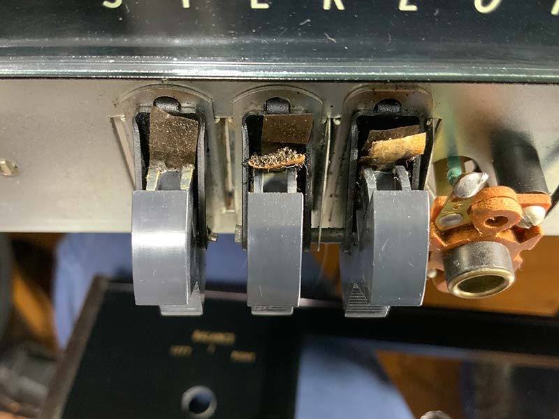
FIGURE 13. Front panel rocker switch foam deterioration.
Component Selection
Given the C22 is an audiophile-grade preamplifier, I gave extra thought to component selection. Instead of the $1 orange drop capacitors I typically use for tabletop AM/FM receivers, I went with coupling capacitors in the $2-$7 range. Similarly, I chose better electrolytics in the $5-$10 range — all rated “high temperature.” Can electrolytics were purchased from Hayseed Hamfest LLC (hayseedhamfest.com), my long-time go-to for custom and hard-to-find replacement can electrolytic capacitors.
The cost of recapping might seem excessive, given there’s about 30 capacitors. It’s definitely the case of diminishing marginal returns. Compared with the $1 capacitors, $7 oil coupling capacitors have slightly lower value drift over time, a slightly lower equivalent series resistance, and a little higher parallel equivalent resistance.
Moreover, component selection is relative. Just as you can outfit the C22 with tubes for $600 each, “audiophile grade” capacitors start at around $65 per capacitor. These capacitors typically have solid silver leads and pure silver, aluminum, or copper plates. They’re also large — around the size of a C or D battery, depending on the value and voltage rating.
I did look into the cost of recapping the C22 with these super expensive capacitors, but, luckily, they were too large for the chassis. That was a relief, and I opted for the middle ground “audio grade” capacitors.
Power Supply Upgrade
The standard power supply upgrade for audio gear from the ‘60s involves substituting silicon for selenium rectifiers, replacing dry electrolytic capacitors with fresh electrolytics, and adjusting the voltage down to specification with a resistor or zener diode. This upgrade is simplified in the C22 because the power supply module is easily extracted from the chassis as in Figure 14.
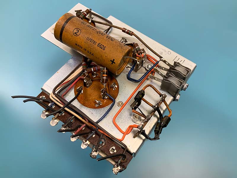
FIGURE 14. Extracted power supply before upgrade.
As you can see from the figure, the power supply has already gone through one silicon/selenium upgrade. The selenium rectifiers used in the tube filament line were replaced with silicon rectifiers. This modification was recommended by McIntosh in the late ‘60s. You can also see the scorched terminal strip.
Today, the modification will focus on the high voltage output of the power supply. Result of the modification is shown in Figure 15. Note the four silicon diodes where the selenium rectifiers used to be. I put several layers of electrical tape below the new bridge to prevent arcing between terminal connectors and the chassis.
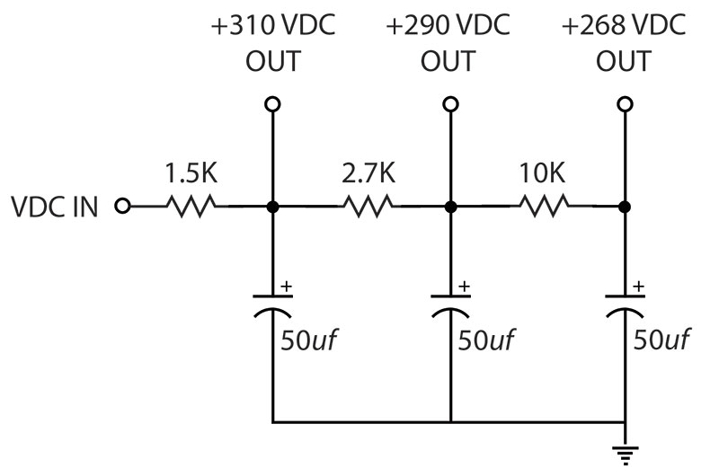
FIGURE 15. Power supply output voltage check. Capacitor tester (left) is used to check electrolytic capacitor leakage.
Figure 16 shows the original schematic diagram of the high voltage power supply. There is a series of voltage drop resistors, each dropping the output voltage by a predetermined amount to 310, 290, and 268 VDC.
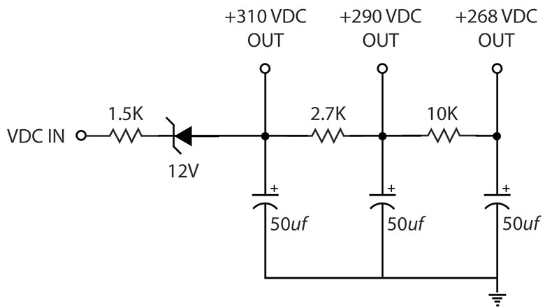
FIGURE 16. Original power supply voltage divider.
Figure 17 shows the upgraded power supply voltage divider circuit. Resistor values remained unchanged, but a 12V zener diode is inserted in series with the high source. The 12V zener compensates for the lower forward resistance of silicone diodes vs. the selenium originals.
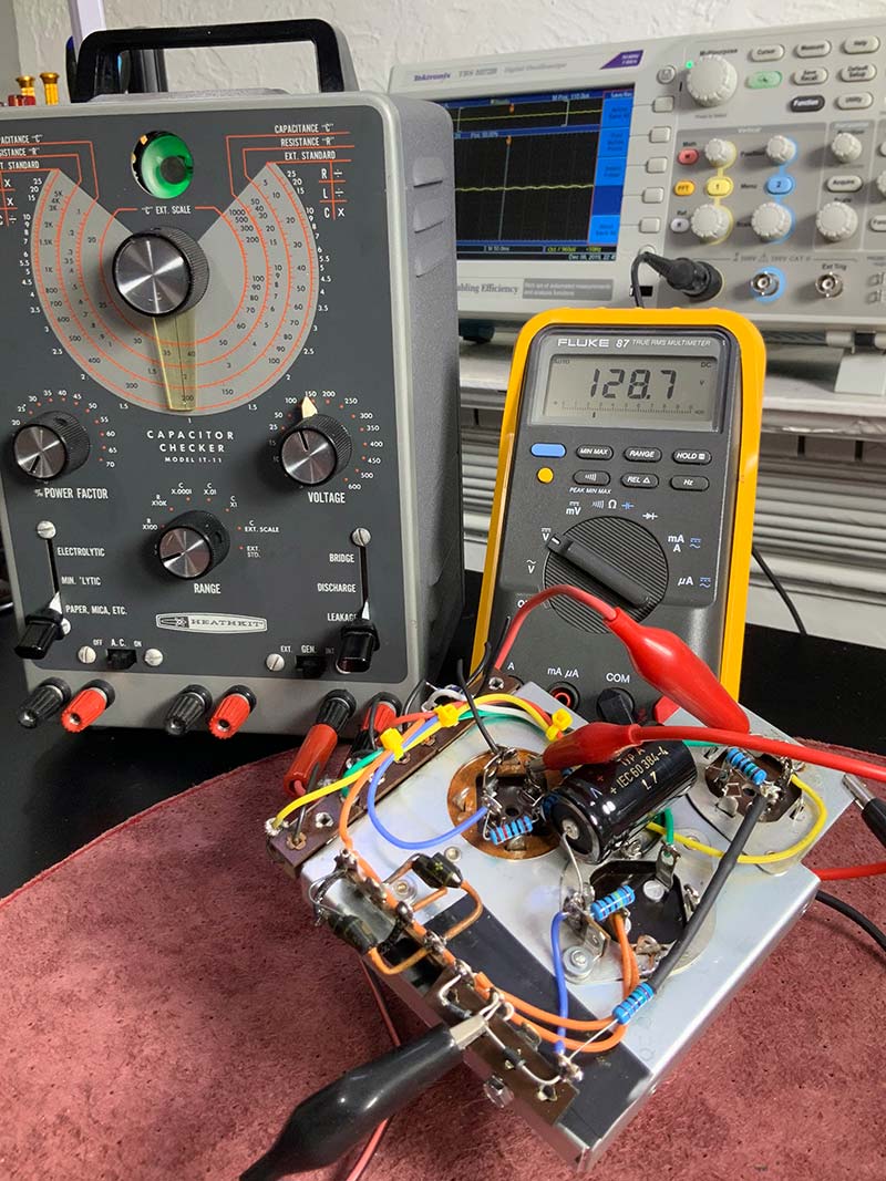
FIGURE 17. Upgraded voltage divider circuit.
Figure 18 shows the refurbished power supply terminal strip. I replaced the tan power resistors and upgraded the power supply wires to flexible, high-temperature silicone encased wire.
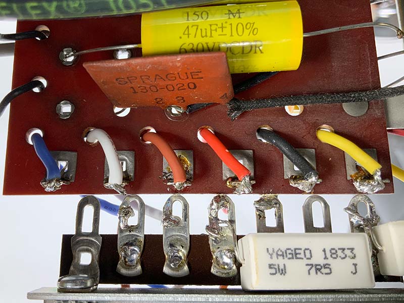
FIGURE 18. Refurbished power supply connector strip.
Recapping
Recapping was straightforward because every capacitor was exposed. All potentially problematic capacitors we recapped, following the polarization of the original capacitors. Figure 19 shows the status of recapping mid-process on the underside of the unit. Note an original .022 µF bumblebee capacitor at the top of the figure and a modern .022 µF at 630 VDC at the bottom.
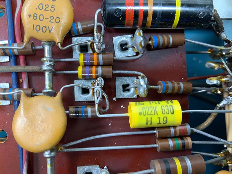
FIGURE 19. Recapping, showing a replacement capacitor and original bumblebee capacitor.
Similarly, Figure 20 shows the recapping process from the top of the unit. The capacitors I chose for this project are about a quarter of the size of the originals despite a much greater voltage rating.
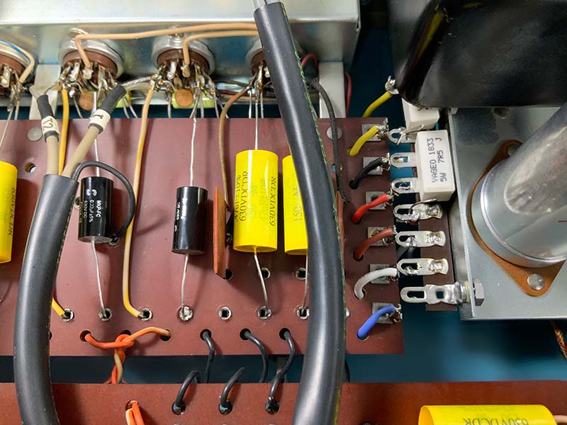
FIGURE 20. Recapping from top of unit.
Potentiometer Cleaning
Next, with full shop ventilation on, I carefully sprayed switch contacts and pots with CRC QD Electronic Cleaner. I waited 24 hours and repeated the treatment. After the second application of cleaner, I used a fiberglass pen (Bergeon 6240) on the visible rotary switch contacts. I finished off the pots and switch contacts with a few drops of DeOxidizer applied with a toothpick.
Display Upgrade
The display upgrade consisted of replacing the incandescent bulbs on the sides of the front panel glass display, as well as the rotary switch position indicators with LED equivalents (see Figures 21 and 22).
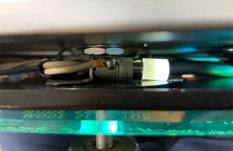
FIGURE 21. LED rotary switch position indicator.
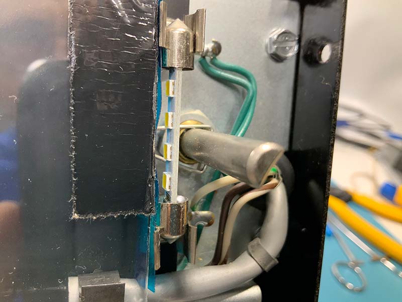
FIGURE 22. Front panel LED side light.
It’s a pain to replace the rotary switch indicator because you have to completely remove the front display from the preamp. However, new bulbs require less than a quarter of the original current and shouldn’t burn out in my lifetime.
Figure 23 shows me repairing the front panel light blocker (a small piece of foam) to keep the light focused on the edge of the glass front panel. The original foam block pieces turned to dust that had to be removed with compressed air.
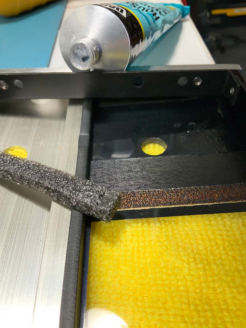
FIGURE 23. Repairing front panel light blocker.
Ohmmeter Check
The ohmmeter check of the circuitry was limited to the power supply module, which passed. Unfortunately, I didn’t extend my investigation to the entire preamplifier, given that I believed the problem to be isolated to the power supply.
Power On Check and Rewiring
Because of the very odd damage to the power supply, I used a Variac, current limiter, and isolation transformer for the power-on test. Refer to Figure 24. The current limiter (which I designed and built) uses light bulbs alone or in combination to limit the current delivered to the preamp.
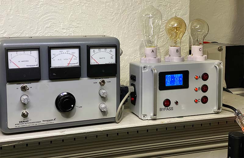
FIGURE 24. Variac, current limiter, and isolation transformer used for power-on check.
I selected a single 30W bulb for the current limiter and slowly increased the Variac output. When I reached 60 VAC, I noticed heat damage to two resistors in the power supply, shown in Figure 25. I immediately shut off the power and traced out the problem.
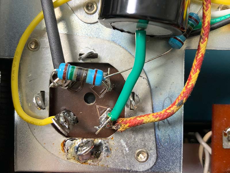
FIGURE 25. Upgraded power supply showing damage to two resistors.
The resistors had begun to fail because, apparently, when the technician upgraded the first set of selenium rectifiers in the ‘60s, he also switched the output wire mapping to resemble Figure 26.
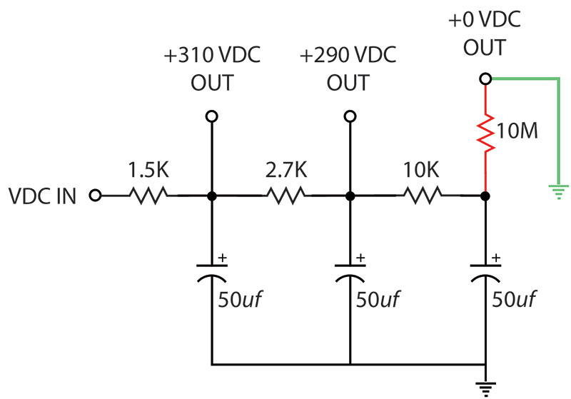
FIGURE 26. Modified voltage divider circuit.
It looks like in the process of replacing the power supply module, he switched the last high voltage output to ground instead of the plates of tubes. Then, when someone opened the chassis and found the burnt-out resistors, he replaced them and either didn’t see or didn’t care about rewiring.
After correcting the wiring error, I repeated the power-on test with the current limiter in the circuit. I also replaced the damaged resistors with fresh ones. The original resistors hadn’t changed values, but they needed to be changed to avoid problems later.
Adjustment
There were no real adjustments to make on the unit. Users can change the settings on the top of the unit for some personalization. Otherwise, it’s plug and play
Reassembly
Reassembly entailed remounting the top and bottom covers on the chassis and reattaching the clean front panel to the unit.
Burn-In
Figure 27 shows my restored C22 undergoing 24 hour burn-in. The only real cosmetic differences between the original and restored units are a brightly illuminated front panel and fresh felt washers just visible under each knob.
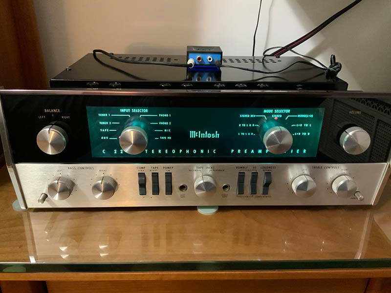
FIGURE 27. Restored C22 during burn-in.
Every hour or so of the burn-in period, I changed the signal source with the illuminated rotary switch to verify each of the eight channels was functioning properly. The small blue and black box atop the C22 is a Bluetooth receiver that feeds the AUX input of the preamp.
After burn-in, I put the C22 in a custom case from RROC3601 on eBay ($285). I’ve ordered several cases from this eBay store, all with good results. There are also less expensive case options, including no case at all.
McIntosh products are finished so well that they look great without being covered by a case. Some say they look best uncovered. NV
Mass Recapping vs. As Needed
Some audiophiles test each capacitor and replace only those found to be defective. My approach on this C22 project was to perform a mass recapping, in part because I was already in the belly of the beast, and in part because all electrolytic and paper capacitors eventually fail. I did, however, save all the original capacitors in the unlikely event that I sell the unit to someone who cares about the original components.
Trust but Verify
This C22 was an eBay purchase. The seller had a 100% rating and was responsive to my questions about the device. It was listed as “taken from a working system” and there were numerous photos of the C22 with the power on. However, in the process of restoring the preamplifier, I discovered some major problems with it, including rewiring of the high voltage power supply. In retrospect, I should have worked down my checklist to verify the wiring before applying power.
RESOURCES
Rroc3601 ebay Store - McIntosh custom cases.
www.mcintoshaudio.com/history.htm
Antique Electronic Supply (tubesandmore.com) - Handles just about everything, from metal can capacitors to schematics of vintage radios.
HiFiEngine.com - Manuals and schematics for vintage radios.
The Valve Museum, http://www.r-type.org/. Detailed specifications on just about any vacuum tube ever produced.
TubeDepot.com - My go-to source for vacuum tubes.