As with any sort of antique restoration project, there can be pitfalls. This article examines the “curtain burner” or those 1930’s radios that were furnished with a resistance line cord that supplied vacuum tube filament voltage as well as power to the radio itself. I’ll look at how possibly restoring these types of radios can be problematic and how to safely restore them.
The Background
The early 1900s were an exciting time for radio manufacturers as well as for consumers. The advent of the home radio was a boon to family life, offering families a place to gather and listen to news and entertaining radio broadcasts (only the Shadow knows …) in the days before television.
In the early 1920s, radios were rudimentary sets operated on battery power using both A (filament-low voltage) and B (plate-high voltage) batteries, often in conjunction with C (grid) batteries to supply the vacuum tubes and electronics that made them work.
As time progressed and radios became more sophisticated, AC-DC sets were developed that could run off the urban power grid (AC or DC) in populated areas, but were also usable in rural settings that could run off generators. During this era of variable voltage sources, power supply requirements in radios changed.
In the mid-to-late 1920s, radios were large and heavy, and in some cases, were even valued pieces of furniture to adorn your living room. By the late 1920s, radio manufacturers saw the value of making smaller tabletop sets such as the rectangular, cathedral, and tombstone styles, but these were still big and heavy.
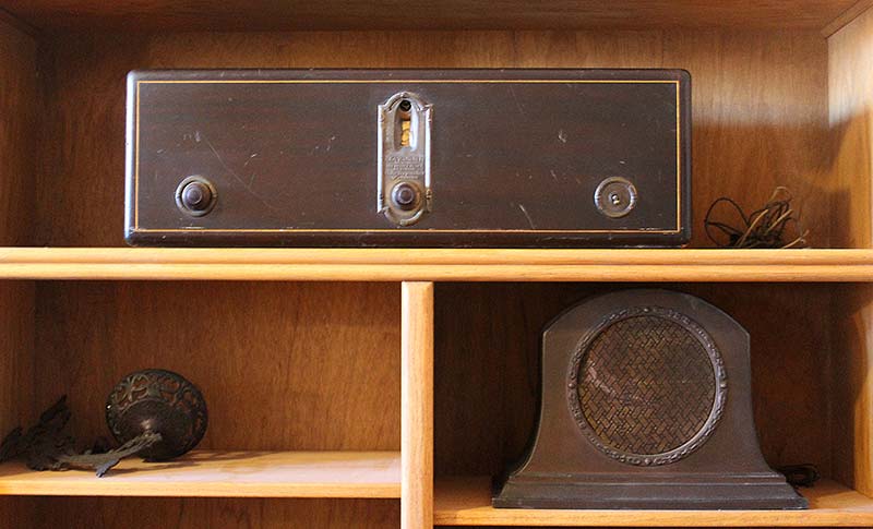
Figure 1. A photograph of an old tabletop set: an RCA Radiola 17 built in 1927. It’s big and heavy.
This “tabletop” version weighs 52 pounds including the external speaker (speaker shown below, right) and measures about 28 inches long.
In the 1930s, manufacturers were trying to make radios smaller, lighter, and less expensive, probably as a result of the Great Depression, thus the All American Five (AA-5) radio was designed; so named because it used only five vacuum tubes and had no power transformer. Power supply issues, however, still had to be addressed.
The Problem
My radio collection includes 16 sets in various stages of restoration dating from 1921 to the late 1940s, one of which stands out: the Grunow Model 501. The set was made in 1933 and was one of the earliest AA-5 sets (Figures 2 and 3).
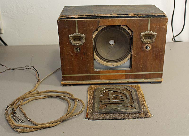
Figure 2. The little Grunow seen with most of its pieces. Note the power cord and what’s left of the plug. No polarized blades there.
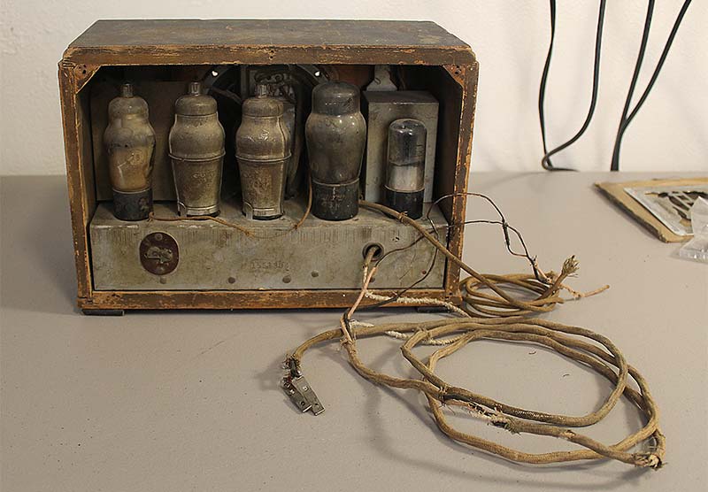
Figure 3. The Grunow as seen from the back. The white insulation on one wire of the power cord going into the chassis is asbestos.
It may look rough at this point, but it’s complete with the exception of the back panel.
The Grunow 501 was smaller and much lighter than many of the period tabletop radios, being only about 12 inches long and weighing in at 10 pounds. This was possible because the power transformer used in bigger sets was removed, making it lighter and less expensive, but the set still used the same vacuum tubes as those in the larger standard types of radios. The voltages for the tube filaments in series needed to add up to and drop the supply voltage, which at the time was somewhere between 110 to 120 volts and was more likely somewhere around 115 volts.
The partial schematic in Figure 4 adapted from the 1934 Volume IV, Perpetual Trouble Shooter’s Manual by John F. Rider (see the sidebar and Resources) shows the power supply side of the radio.
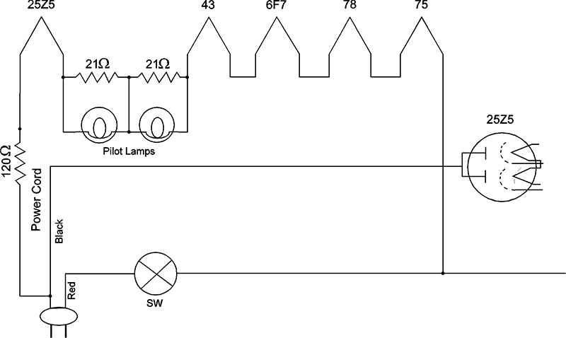
Figure 4. A portion of the schematic showing the power supply section of the radio. Note the series filament string and 120 ohm resistance wire to keep filament voltage in check. The schematic is adapted from Rider 1934.
The filaments had two pilot lamps wired in series with resistors in parallel to the lamps to keep everything running if a lamp burned out.
The tube types are 25Z5, 43, 6F7, 78, and 75, as shown on the schematic. Although most vacuum tube alphanumeric designations indicate filament voltage in the prefix (the 25Z5 tube has a 25 volt filament rating), some old tubes don’t adhere to this standard.
For instance, two of the six volt filament tube types in the Grunow are listed simply as 75 and 78, and the last 25 volt filament tube is simply type 43. Using GE’s “tubes essential characteristics” (again, see the sidebar and Resources), the filament voltages in the Grunow would thus add up to about 69 volts at 0.3 amps. Assuming a line voltage supplied by the power company of 115V, an additional 46 volts (or so) would have to be dropped to avoid burning out the filaments.
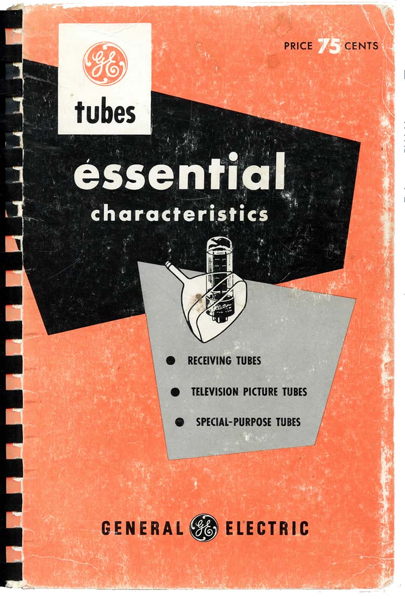
One of most valuable resources for anyone working with vintage tube-type electronic equipment is the General Electric “tubes essential characteristics” book (shown). It contains helpful information on the design purpose and use of vacuum tubes with technical tube specifications and other parameters, plus it’s available in pdf format (see Resources).
Another valuable resource is the Rider Perpetual Trouble Shooter’s Manual (not shown). I believe it’s 27 volumes for the complete set, and contains schematics for 1920s to 1950s vintage radios, as well as parts lists and alignment procedures. The manuals are also available in pdf format (see Resources). I was able to print schematics for radios I’m working on.
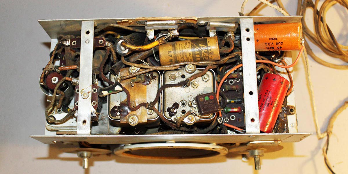
The problem the manufacturers faced was how to drop the line voltage without using a power transformer in the radio. Their solution was to install a resistance line power cord to the radio, where two of the three wires in the cord carried the full voltage to the radio and the third (resistance) wire supplied the tube filaments. Anticipating the amount of heat that the resistance wire would generate, it was insulated with asbestos; Figures 3 and 5 show what’s left of the resistance power cord to the Grunow.
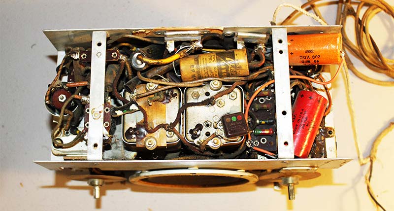
Figure 5. The underside of the chassis. The resistance wire insulated with asbestos ouside the rest of the power cord is seen entering the chassis on the upper right. Note two newer capacitors installed by a previous owner.
As you can see, it’s deteriorated and broken from constant exposure to heat; so much so that radios using these types of resistance line power cords were not so affectionally called curtain burners. Although it was thought that the six foot resistance power cord would be able to sufficiently dissipate the heat satisfactorily (think wattage here), it was an unfortunate radio owner who chose to bundle the cord or route it to the outlet inappropriately, causing it to overheat and inadvertently start a fire.
Later radio manufacturers of AA-5 radios solved this problem by using newer tube designs that had higher collective filament voltages and lower amperage ratings that helped to accept power line voltages more appropriately. For instance, a typical later model AA-5 radio might have filament voltages that added up to about 122 volts at 0.15 amps, thus eliminating the need for the resistance line cord.
The Fixes
To avoid getting nasty looks from my wife if I accidentally set our living room curtains on fire, I needed to repair the Grunow correctly. As with any electronics restoration, there are different schools of thought on the best approach for repair. I’ll present four possible fixes for this, each with their own pros and cons.
Assuming a modern city supply voltage of about 120 volts, roughly 51 volts would need to be dropped to the filament circuit to get the radio working properly. Simply installing a modern line cord won’t work because it won’t provide the necessary voltage drop to the filaments (disastrous), and using any other type of resistance “quick-fix” could be problematic in terms of generated heat.
I could use a new old stock (NOS) resistance power cord since they still seem to be available online, but not only is the resistance wire design a possible problem (burnt curtains), I assume their resistance values could vary, possibly damaging the radio. Further, the very age of NOS can be a problem.
As can be seen in Figure 4, the power cord for this radio had a 120Ω resistance built into the wire which generated heat and — just like a light bulb — resistance generates heat. A second fix would be to install a large power resistor on the chassis, but as seen in Figure 3, there isn’t much room to add additional components in the Grunow.
With no room for a back panel with larger components installed, there’s the danger of possibly touching live components when in use. For these same reasons, a power transformer is probably not practical. A possible final fix would be to install a capacitor or capacitor and resistor (not an electrolytic capacitor) which would work to provide the correct voltage drop. A fair amount of math is necessary, however, to calculate the correct component values.
Paul Stenning’s spreadsheet for these calculations (which is Microsoft Excel compatible) can be found on his UK Vintage Radio Repair & Restoration website under Dropper Calculations (Stenning 1997-2006; see Resources). Although the spreadsheet was created in the UK, standard electronic principles still apply and the correct values for voltage and line frequency can be input.
Using this spreadsheet for the Grunow and its tube lineup, the value for the capacitor should be 8.81 µF and the resistor 33 ohms at 3.0 watts. The capacitor should be rated for voltage as high or higher for this application. I’m not sure what exact component specifications or tolerances need to be if specific values are unavailable. Component values listed here are specific to this project restoration and should be considered an example only since no two pieces of equipment are the same.
This last possible fix seems to be the best since it may require less space for component placement and should produce less — if any — heat at all. One last consideration is to always use a polarized plug for the line cord.
The Next Step
Although this article focuses on the resistance power cord, there are other steps necessary to resurrect this 88 year old Grunow. My goal is to bring new life to the radio, and still retain its original character.
First, it appears a previous owner has already replaced two capacitors under the chassis (Figure 5), but they may be old as well, and may need to be replaced along with other original capacitors. As can be seen back in Figure 3, some definite cleanup is also necessary.
I have all the cabinet parts (minus the back panel) and the two wood knobs for volume and tuning. The back panel can be fabricated. The speaker has a tear, which can probably be fixed to avoid replacing it, and I hope to reamalgamate the existing finish on the wood-veneered cabinet to avoid having to do a complete refinishing job. With that, it can still look good and retain its original character that time has given it.
In this modern era of advanced technology, there’s nothing more rewarding than hearing a radio broadcast on a piece of history that’s approaching 100 years of age that you brought back to life and can enjoy again.
Safety
Vintage radios with resistance power cords and other pieces of early tube-type electronic equipment carry high voltages which can cause harm or even be lethal. Caution must always be observed when working on these!
The power cord on the Grunow had been completely destroyed, but if it had been in decent condition someone could have plugged it into a wall outlet possibly hurting themselves and the radio itself. The potential to have a “hot” chassis or other metal components such as the potentiometer or tuning shafts (without knobs), and even exposed screws could pose a shock hazard.
Additionally, some early radios could have a hot chassis or other metal components when turned on, or be hot when turned off depending on non-polarized plug orientation and radio wiring.
Using an isolation transformer is a good idea since it can help reduce the risk of problems by eliminating a possible direct conduction path to the line voltage. Bear in mind, however, that an isolation transformer does not eliminate the possibility of exposure to the high voltage circuitry.
Using a variac or some other type of variable AC power supply (autotransformer) to bring up supply voltage gradually and a dim-bulb tester are also good ideas. (Many of these safety issues have been identified in previous issues of Nuts & Volts.)
The resources mentioned in this article can help, but it’s up to the technician or hobbyist to evaluate the safety risks for any particular project. I welcome all suggestions and thoughts on this project, and any other solutions you may have for powering-up your old curtain burner. NV
Resources