Smiley's Workshop — AVR C Programming Workshop Series - Part 15
Last episode, we learned to measure light and temperature, and faked showing decimal numbers from data stored as integers. This time, we are going to learn about IR (infrared) object detection.
Recap
In recent Workshops, we’ve been using a new development board and components kit: the Arduino Duemilanove and the Arduino Projects Kit. We recognized that The Arduino Way (TAW) is a very simple and easy way to begin using microcontrollers. And we learned that while TAW uses a C-like language, it does not (IMHO) provide a clear path to learning the C or AVR architecture — both of which are our long-term goals for this Workshop series. So, we were introduced to A C Way (ACW) that uses more standard (again IMHO) AVR tools. We decided to discuss projects using the kit with TAW, but also provide the software ACW in the Workshop zip file for those ready to move on. After we’ve introduced all the kit parts, we will then move exclusively to ACW since we will be looking at issues that are more difficult to accomplish with TAW (such as using timer interrupts).
But Is It Light?
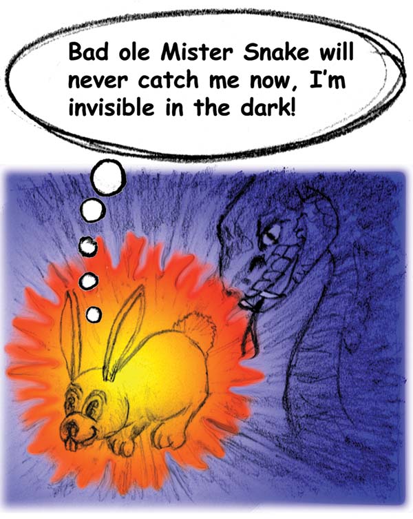 |
| FIGURE 1. Cute L’il Bunny has her last thought. |
In Figure 1, we see Cute L’il Bunny in the dark having her very last thought. What she doesn’t know is that bad ol’ Mr. Snake is a pit viper and has a couple of IR Object Detectors located in pits on either side of his head between his eyes and his nose. These sensors allow him to triangulate on objects that are hotter than the surrounding environment, such as bunnies that think they are well hidden in the dark but are actually glowing brightly to the snake. Yum.
William Herschel accidentally discovered infrared radiation in 1800. He used a prism to split sunlight into colors and placed thermometers along the spectrum to measure the temperatures of the colors. He was shocked to note that the hottest part occurred in the unlit area just below the visible red zone, which he named infrared (infra means below). [Incidentally, in 1781 he discovered Uranus, but I don’t know if thermometers were involved.]
We cannot see IR with our eyes, but if the source is intense we can ‘see’ it with our skin as the perception of warmth. You can close your eyes tightly and find a nearby heater by holding your palms out and turning around until you feel the heat — this isn’t exactly high resolution ‘seeing’ but it is ‘perceiving’ IR light.
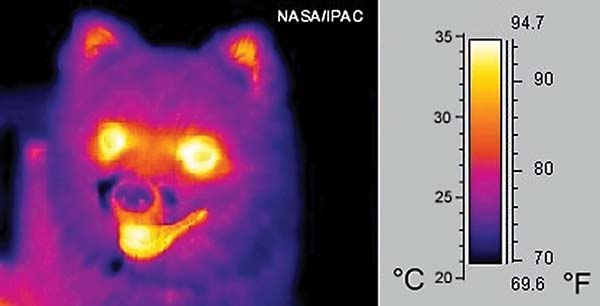 |
| FIGURE 2. Dog IR thermoscan. |
You might think it would be cool if we could see IR with our eyes. Well, think about that for a moment. Since we operate at 98.6° F, we — like that poor bunny — are beacons of IR light and if we could see it we would be blinded by the emissions in our own eyeballs. Snakes can use IR because they are cold blooded. Figure 2 shows a NASA thermoscan of a dog that — in addition to looking really creepy — provides a false color view at how the dog might appear to something that can see IR.
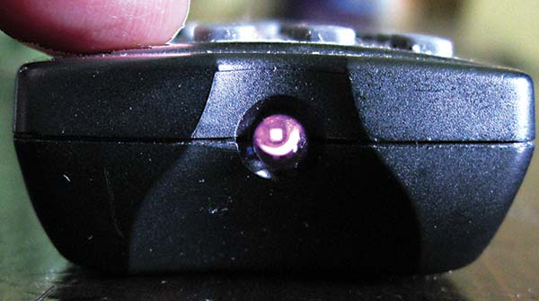 |
| FIGURE 3. Digital camera ‘sees’ TV remote IR. |
Even though you can’t see IR with your own eyes, you can detect it with a digital camera. Just hold a TV remote pointed at your camera (even a cellphone camera will show this) and press the power button. With your eyes you see nothing but as shown in Figure 3, the camera shows a light.
Some Common Uses For IR Sensors
One of our most common electronic IR emitters is, of course, on that blessing to couch potatoes everywhere: the TV remote control. It broadcasts a coded IR signal to the IR detector on the TV console that decodes the signal and saves you the excruciating drudgery of waddling over to the TV to change the channel.
And where would the military be without IR for target acquisition? Fire a Sidewinder missile (named after a pit viper) at the exhaust pipe of your enemy’s jet and say good-bye to your little friend. Another cool way to improve your kill skill is with night vision goggles. This way you can be like Mr. Snake.
There are many other uses, such as on a factory production line that senses tomato soup cans passing on a conveyer belt. This is much more boring than blasting enemies (or eating bunnies), but that’s the practical example we will construct by the end of this Workshop.
IR Reflective Object Sensor: The QRD1114
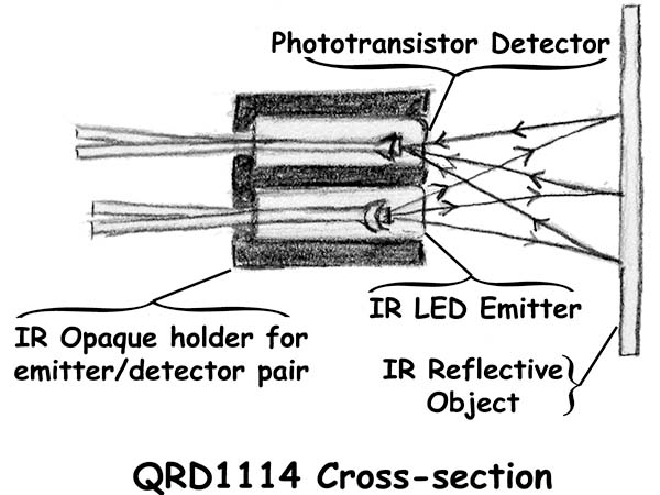 |
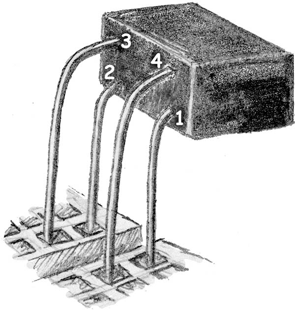
| FIGURE 4. QRD1114 cross-section. |
The Arduino Projects Kit has an IR Reflective Object Sensor (the QRD1114) that we will use for several projects. The QRD1114 is made from an IR LED emitter, an IR phototransistor detector, and an IR opaque shield that holds them together. You can remove the emitter and detector by holding the legs and pushing toward the front of the device. If you do this, remember which way the legs were so that you can get it reassembled properly. Also remember to watch for protruding beyond the shield, as this will radically affect the way the device works. The functional concept is simple: The shielded emitter radiates IR from the open end which can only be seen by the shielded detector if the IR bounces off something. This is shown in a cut-away view in Figure 4.
Making IR Visible
The QRD1114 must be calibrated to a specific application to be used to its greatest effect. Calibration is necessary for two main reasons: 1. The sensor detects IR not just from the reflections of the associated emitter, but from ambient (environmental) IR; and 2. The amount of IR reflected back from the emitter varies with the IR reflectivity of the reflecting object and the distance to that object.
IR Doesn’t Know Black From White
White reflects all visible light and black absorbs it. You might think that a white area would reflect more IR back to the sensor than a black area. I did, but it turns out that the operative part of the definition of black and white is ‘visible.’ Some things that appear black and white to me reflect the same amount of IR and look identical to the IR sensor. I printed my first motor wheel encoder on photographic paper and my detector couldn’t tell the difference in the white and black bars.
Naturally, I assumed that the problem was something in the software or hardware and spent a lot of time looking for a bug. It turns out that printing the same image on plain paper works pretty well. Apparently, the shiny surface of the photo paper is transparent to the human eye but reflects the incidental IR. I found that I got an even better sensor reading if I went over the plain paper printed black areas with a black Sharpie© ink pen. Again, I couldn’t see much difference but the detector sure could.
Breadboard: Show Invisible IR Intensity With Visible Red LED
 |
| FIGURE 5. QRD1114 reflective object sensor. |
You can see a drawing of the QRD1114 along with its schematic symbol in Figure 5.
 |
| FIGURE 6. Bending the QRD1114 legs. |
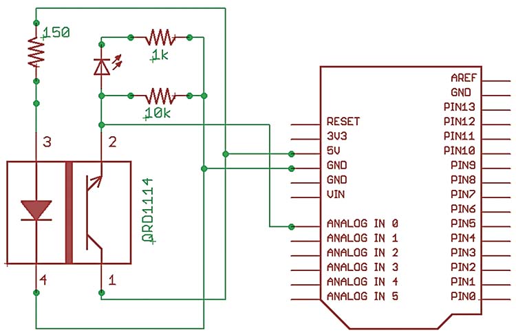 |
FIGURE 7. Object detector schematic.
|
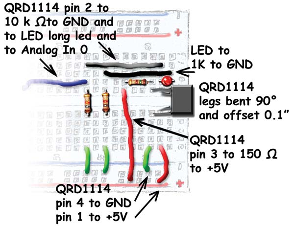 |
| FIGURE 8. IR object detector layout |
We are going to carefully bend the legs on the QRD1114, as shown in Figure 6, so that we can mount it on the end of the breadboard with it ‘looking’ to the horizontal. Be very careful when you bend these legs and even more careful when you trim them to fit in the breadboard. The legs will break if bent more than a couple of times so make sure you get it right the first time. It is very easy to lose track of which leg goes where and since you only get one of these in the kit, you don’t want to screw this up. Bend the legs that go to the phototransistor straight down to the side and then bend the IR LED legs in the same direction, but make the bend a little over 0.1 inch from the bottom. Next, trim them so that they will fit in the breadboard with the face of the sensor at the edge of the breadboard (but not overlapping the foamcore base since that edge slides into the ALP box). The breadboard schematic is shown in Figure 7 and the layout in Figure 8. Figure 9 is a photo of the IR object detector.
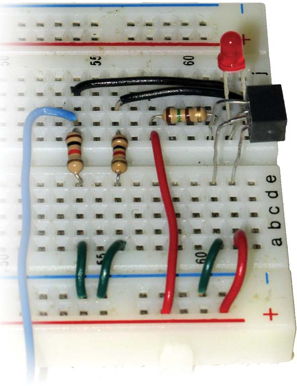 |
| FIGURE 9. IR object detector photo. |
As you can see from the schematic, a red LED has been inserted into the circuit that has its brightness controlled by the detector, providing us with a visible cue for the amount of IR being detected. The IR light falling on the phototransistor base provides the bias current that controls the collector emitter current that flows through the LED. You can move your finger back and forth in front of the sensor and the red LED will brighten or dim in response. This is a purely analog response and could — with proper amplification — be used to drive some other analog device such as a motor.
We can get a digital measure of this response by putting a 10 KW resistor from ground to the phototransistor and running a wire from that point to the Arduino ADC in analog input pin 0 as shown in the schematic. Let’s apply this to a real-world experiment (and by ‘real’ I mean ‘contrived’).
Tomato Soup Can Counter
 |
| FIGURE 10. Tomato soup can counter prototype. |
I went a little overboard when I did this experiment. I made a foamcore board ‘conveyer belt’ where I placed six Tomato soup cans (reduced sodium for a healthier experiment) and dragged them past the sensor to get calibration values. Figure 10 shows the device in the starting position and after the cans have been conveyed past the sensor. As for the construction details, I used foamcore board and masking tape, and eyeballed everything. So should you — it’s a prototype, so expect imperfections. The ‘belt’ should be a little wider than a soup can and long enough to hold six cans (which is the number I had in my pantry), while the ‘base’ should be just slightly wider than the belt so you can slide the cans past the QRD1114 as shown in the pictures. The IR detector should almost touch the soup cans as they pass by to get a good reflection.
Tomato Soup Can Counter Software
You have no way to predict the ADC values for the IR returned from a particular object other than it will be between 0 and 1,023. I did preliminary tests using the ReadPot TAW source code in the Arduino IDE (from Smiley’s Workshop 12) and substituting the detector for the potentiometer. The data shown in Figure 11 varied from a low of 145 to a high of 799 for my finger (your finger will probably be different).
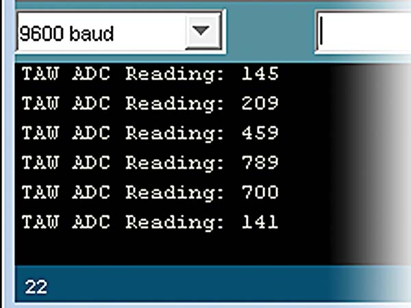 FIGURE 11. ADC readings of finger movements. FIGURE 11. ADC readings of finger movements. |
| |
When I set up the soup can conveyer and slowly moved a can past the sensor while observing the results from the ReadPot TAW software on the Arduino Serial Monitor (slow since the code is only measuring once per second), I saw a range of values above (>600) which I could be certain that a can is present and another range below which I could be sure there was no can present (<300). There is also a sloppy mid range where I couldn’t be sure (301 to 599). Remember your values won’t be the same as mine. You must make your own measurements to determine the certain ranges: YES_CAN and NO_CAN, then use a true/false variable ‘yes’ to decide if a can has passed the sensor. There really are many ways to do this kind of thing, but I selected the easy (for me) to understand logic of:
If the analogInput is greater than YES_CAN and yes is equal to 0, then set yes to 1. Else if analogInput is less than NO_CAN and yes is equal to 1, then set yes equal to 0 and increment the can count.
Think about this for a moment from the perspective of a can moving by the sensor. Before the can gets there, ‘yes’ is equal to 0 for false and the analogInput value is less than the YES_CAN constant we have predetermined that indicates a can is present. As the can moves into view of the sensor, at some point analogValue becomes greater than YES_CAN so we know there is a can and we set ‘yes’ equal to 1 for true (yup, there is definitely a can present). Then, we keep measuring as the can slides past and the analogInput drops to a value less than NO_CAN. We check and see that ‘yes’ is true, so there was a can, but now our analogInput reading says there is no can, so it must have passed by. We set ‘yes’ to 0 and increment the can count. Whew! This will probably be clearer from reading the source code.
I put YES_CAN and NO_CAN in the Tomato_Soup _Can_Counter source code as hard-coded constants (this is not a good programming practice, but it is useful here for keeping things simple).
// Tomato_Soup_Can_Counter<br />
// Joe Pardue June 27, 2009
// Sensor level constants<br />
#define NO_CAN 300<br />
#define YES_CAN 600
// O if NO_CAN, 1 if YES_CAN<br />
int yes = 0;<br />
// Can count<br />
int count = 0;
// variable for analog input value<br />
int analogValue = 0;
void setup()<br />
{<br />
  // begin the serial communication<br />
  Serial.begin(9600);<br />
}
void loop()<br />
{<br />
  // read the analog input on pin 0<br />
  analogValue = analogRead(0);<br />
 <br />
  // print prolog to value<br />
  Serial.print(“ADC Reading: “);         <br />
  Serial.print(analogValue, DEC);<br />
 <br />
  // If the analogInput is greater than YES_CAN<br />
  //  and yes is equal 0 set yes to 1.<br />
  // If analogInput is less than NO_CAN<br />
  //  and yes is equal 1, set yes equal 0<br />
  //  and increment count.<br />
  if ((analogValue > YES_CAN) & (yes == 0)){<br />
    yes = 1;<br />
    Serial.print(“ - YES_CAN”);<br />
  }<br />
  else if ((analogValue < NO_CAN) & (yes == 1)){<br />
    yes = 0;<br />
    Serial.print(“ - NO_CAN”);<br />
    count++;<br />
  }  <br />
 <br />
  // show the count<br />
  Serial.print(“ count = “);<br />
  Serial.print(count, DEC);<br />
 <br />
  // print a newline<br />
  Serial.println();<br />
 <br />
  // delay 1 second before the next reading:<br />
  delay(1000);<br />
}
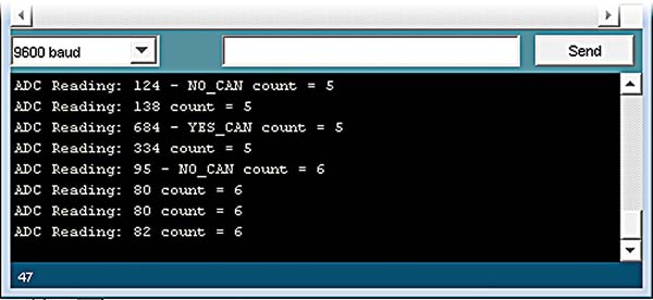 |
| FIGURE 12. Can count on Arduino serial monitor. |
For this demonstration, I kept the time between ADC readings at one second to avoid being overwhelmed with serial data. When I first tried counting the cans, I got some weird can counts and found that I had to make my conveyer belt narrower so that the cans were all pretty close to the sensor when they passed. The serial output is shown in Figure 12.
Once you get the system calibrated, you should be able to remove the serial output and the one second delay, and set a flag so that you only output the count when it changes.
Please note that you should leave the detector circuit in place on the breadboard for next month’s article. NV
You can find the source code and supplements for this article in Workshop15.zip in the downloads section of the Nuts & Volts website and Smiley Micros website.
The Arduino Projects Kit
The Arduino projects kit is a special hardware pack that will help you get hands on experience as you follow along with this series. It provides components for use with Workshops 9, 10, 11, and many future Workshops. Over time, we'll learn simple ways to use these components, and more importantly, use them to drill down into the deeper concepts of C programming, AVR microcontroller architecture, and embedded systems principles.
The Arduino Projects kit is offered through the Nuts & Volts webstore and Smiley Micros website.
Back to top
Downloads
Smileys Workshop 200910 (Workshop15.zip)