AVR C Programming Workshop Series - Part 3
Last time, we wrote our first C Program: CylonEyes.c, built the CylonEyes hardware, and watched the LED light zip back and forth. This month, we will look at AVR port input and output. And we will add an eight-bit DIP switch to our learning platform.
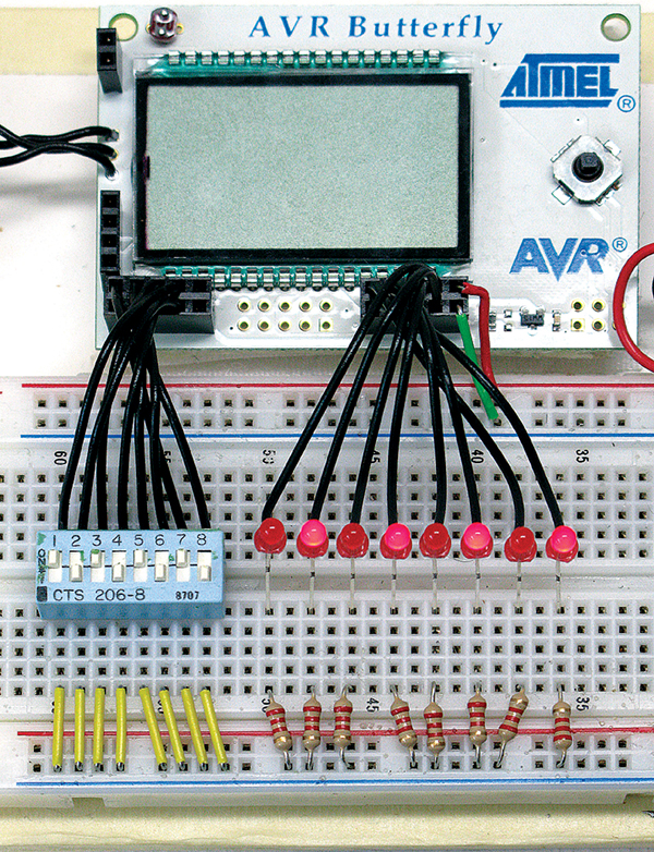 |
| FIGURE 1. Port input and output. |
Remember in Workshop 1 where I compared learning C and AVRs to walking across two continents and said I’d give you some warnings? Well, prepare to have a branch smack you in the face. This workshop has some very tedious facts in it. Sorry, but it can’t all be fun and games and you have to climb a high wall in order to get to the fun stuff. As Randy Pausch said in the ‘Last Lecture’ “... brick walls are there for a reason. The brick walls are not there to keep us out. The brick walls are there to give us a chance to show how badly we want something. Because the brick walls are there to stop the people who don’t want it badly enough. They’re there to stop the other people.”
Data Types and Sizes
Bits — The first computers were people with quill pens who spent their lives calculating tables of things like cannonball trajectories to help soldiers more accurately slaughter their enemies. Later, mechanical computers with brass gears and cams were developed to make the slaughter cheaper, quicker, and easier. Then one day a genius figured that you could do all this computing even easier if you used switches.
Switches can be off or on, and the fundamental datum is the ‘bit’ with exactly two ‘binary’ states. We variously refer to these states as ‘0 and 1’ or ‘on and off’ or ‘clear and set’ or ‘true and false.’ It’s the latter that allows us to use bits to automate Boolean Logic (an ‘algebra’ for determining if a statement is true or false), and thus the modern binary logic computer entered the world and now slaughter is so cheap, quick, and easy to compute that anybody can do it. Maybe this is skimming the topic a bit (har!) but a full explanation would begin with the first sentence of Genesis and only hit its stride about the time Alan Turing offed himself as his unjust reward for saving the free world in WWII. And while fascinating, it won’t get us blinking LEDs any quicker, so let’s move on.
Each of our LEDs is connected to a microcontroller pin that can have two voltage states: ground or Vcc, which can be manipulated as a data bit.
Bytes — The AVR and many other microcontrollers physically handle data in eight-bit units called bytes — a data type that can have 256 states, 0 through 255. This is shown in the following sequence of states (leaving out 5 through 250):
00000000 = 0
00000001 = 1
00000010 = 2
00000011 = 3
00000100 = 4
...(states 5 through 250) ...
11111011 = 251
11111100 = 252
11111101 = 253
11111110 = 254
11111111 = 255
For CylonEyes, what you are seeing is eight of the 256 possible states being presented in a sequence that fools us into thinking we are seeing a back and forth scrolling motion. Using binary numbers where the lit LED is represented by 1 shown next to the binary, hexadecimal, and decimal equivalent, what we are seeing is:
00000001 = 0x01 = 1
00000010 = 0x02 = 2
00000100 = 0x04 = 4
00001000 = 0x08 = 8
00010000 = 0x10 = 16
00100000 = 0x20 = 32
01000000 = 0x40 = 64
10000000 = 0x80 = 128
In microcontroller applications, we will often be dealing with the states of byte-sized ports, like port D. A microcontroller port is a place where outside voltages (0V or 3V) can be read or set. Experienced microcontroller programmers memorize the binary equivalent of hex digits and find hex numbers very useful. For instance, given 0xA9, what would the LEDs (or the voltage states of an eight-bit register) look like? If you memorize the hex table, you come up with 0xA = 1010 and 0x9 = 1001, so the LEDs (voltage states) will look like 10101001. If you ask the same question in decimal, what will 169 look like on the LEDs? Well, good luck on doing that in your head.
char — The name of this data type is short for character, and is typically used to represent a character in the ASCII character set. Originally, there were 127 ASCII characters used by Teletype machines to transmit and receive data. Remember that in Figure 1 of Workshop 1, you saw Dennis Ritchie who wrote C standing next to Ken Thompson who wrote UNIX, working on a Teletype machine. Clunky as they were (the Teletype, not Ritchie and Thompson), Teletypes were light-years ahead of entering data by individual switches representing each bit of data. Teletypes send and receive characters so a lot of C, especially the standard library, stdio, is character oriented. The number of bits in a char is machine dependent, but in all machines I’ve encountered including the AVR, a char is an eight-bit byte that can have 256 bit states. The computer uses this byte of data as representing a signed value from -128 to +127.
unsigned — If the modifier unsigned is used in the definition of a char variable ‘unsigned char,’ the value is from 0 to 255. Many C compilers will have ‘byte’ or ‘Byte’ defined as equaling unsigned char. The byte keyword is not part of C, but it is very convenient, since in microcontrollers we usually use a lot of numbers, but not a lot of ‘char’acters.
int — On AVR microcontrollers, int (short for integer) declares a 16-bit data variable as having values from -32768 to +32767. A variable declared with ‘unsigned int’ will have a value from 0 to 65535.
The long and short of it — Everybody else makes that dumb joke at this point, so why be different? You can declare variables as ‘short int’ and ‘long int.’ For C, the size is machine dependent, but on many systems a short int is the same as an int (16 bits), while a long int is 32 bits.
uint8_t and uint16_t — More recent C standards use uint8_t for an eight-bit unsigned char and uint16_t for unsigned int. This increases portability between machines and lessens confusion about the size of the data type we are using.
Declarations
A declaration is a text statement that declares to the compiler how your words are to be used. When you declare ‘unsigned char counter = 0’ you are telling the compiler that when it encounters the word ‘counter’ to consider it as data stored at some specific address with the alias name ‘counter’ that can have values from 0-255, but in this case, it initially has a value of 0.
Variable Names
The changeable data you are processing is stored in bytes of RAM (Random Access Memory) at specific addresses. Variables are names that provide an alias for the address being used. We’ll look at those gory details in a later Workshop.
Constant Names
Literal constants are data that are not really variables but read-only values that are textually replaced on the first pass of compilation. The literal’s name is traditionally typed in all caps, and located in a header file or at the start of the software module. For example, we might want to use pi in a calculation, so we define as follows:
#define PI 3.1415926
We can then use PI anywhere in our software and the compiler will automatically substitute the numerical value for it (Listing 1).
| Listing 1 |
|
float pieCircumference = 0.0;    // we don’t know yet<br />
float piePanRadius = 2.2;    // this we measure so it can vary
// sometimes you just gotta have PI.<br />
pieCircumference = PI * ( piePanRadius * 2 );
|
Operators
Note: Some of these operators may seem strange at this point, but they are explained fully in later Workshops. Then they’ll seem even stranger. You may already be familiar with some of these operators, and rather than take space elaborating each, we will wait to see how they are used in context in later Workshops.
| Operator |
Name |
Example |
Defined |
| [] |
Array element |
x[6] |
Seventh element of array |
| . |
Member selection |
PORTD.2 |
Bit 2 of port D |
| -> |
Member selection |
pStruct->x |
Member x of the structure pointed to by pStruct |
| * |
Indirection |
*p |
Contents of memory located at address p |
| & |
Address of |
&x |
Address of the variable x |
| TABLE 1. Data access and size operators |
| Operator |
Name |
Example |
Defined |
| () |
Function |
wait(10) |
x converted to a double |
| (type) |
Type cast |
(double)x |
x converted to a double |
| ?: |
Conditional |
x?y:z |
If x is not 0 evaluate y, otherwise evaluate z |
| , |
Sequential evalution |
x++,y++ |
Increment x first, then increment y |
| TABLE 2. Miscellaneous operators |
We will save the Arithmetic operators for Workshop 4 and in Workshop 5 we will look at Logical, Relational, and Bitwise operators.
Okay, I’m tired of all these words, let’s play with some hardware!
Port Input and Output
We skimmed over a lot in Workshops 1 and 2 so that we could get some LEDs blinking. Let’s now take a more detailed look at I/O ports.
AVRs are available with from six to 86 I/O pins (ATmega169 has 54 I/O pins). Most of these pins are organized into eight-bit ports. Many of the pins have more than one possible function. They can be used to input or output digital logic data, they might be used for detecting external interrupts, or for analog-to-digital conversions and so on.
Pins can be set as either Input or Output. Pins set as outputs can be driven to Vcc or Gnd. Pins set as inputs can have a pull-up resistor enabled or disabled. Each pin can be changed to either input or output without affecting the state of any other pin. This is also true for changing an output pin’s drive value or an input pin’s pull-up resistor enable or disable.
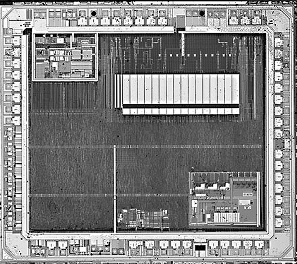 |
| FIGURE 2. ATmega169 |
The ATMEGA169 on the Butterfly has six eight-bit and one four-bit general-purpose I/O ports as shown in Figure 2 (page 3, ATMega169 data book). (You can get the data book from www.atmel.com or as part of the Workshop3.zip*). That diagram looks mighty complex, doesn’t it? Well, it is a simplified block diagram of a circuit that is vastly more complex. When you see a photomicrograph of these chips like in Figure 2, they resemble aerial photos of a vast ancient city with streets laid out in a grid surrounded by a wall. The ports are like the gates to the city. Each pin in a port is configured by three individual bits in registers DDRx, PORTx, and PINxn (see page 74 of the datasheet). For example, port A has PORTA, DDRA, and PINA registers each with eight bits to set up each pin. When used for general-purpose I/O, the port DDRx (Data Direction Register) bits must be set to 1 for output or 0 for input. For example, to use the upper four bits of PORTB as inputs and the lower four bits as outputs, set the bits to 00001111, which in hex is 0x0F:
DDRB = 0x0F;
When a port pin is configured as an input, writing a 1 causes the port pin to be connected to Vcc via a resistor. If it is configured as an output pin, then writing 1 drives the port high (logic 1) or writing 0 drives it low (logic 0).
// enable pull up<br />
// on input port<br />
PORTB = 0xFF;
If you look at the I/O-Ports section of the ATmega169 datasheet beginning on page 52, you will see that there is a bit more complexity to this topic than we covered here, but at least we have enough for now to read and write ports. One thing to remember is that we set a port to a value by writing to the PORTx, but we read a port by reading PINx. For example:
PORTD = PINB;
writes the value off the PORTB pins to PORTD. It is very common for newbies to forget this. In this project, we will set PORTB to input data from switches and PORTD to output Vcc to drive LEDs. We use the PINB register to read the switches from port B and write the value to port D using the PORTD register. Then we write an infinite loop that gets the switch data from port B using PINB and equates it to PORTD that will light the LEDs.
|
Listing 2
// PortIO.c<br />
#include <avr/io.h>
int main (void)<br />
{<br />
       // Set port data direction registers<br />
       DDRB = 0x00;  // PORTB set to input<br />
       DDRD = 0xFF;  // PORTD set to output
PORTB = 0xFF; // enable pull up on input port
       while(1)<br />
       {<br />
             PORTD = PINB;<br />
       }<br />
}
|
Create a new AVRStudio project — PortIO.c — as discussed in Workshop 2 and enter the C code shown in Listing 2. The PortIO source code is also included in the Workshop3.zip.
And as before, compile and download the hex file to the Butterfly. Remember to turn the Butterfly off and back on WITH THE JOYSTICK PRESSED TO THE CENTER! Then, hold down the center joystick button while clicking on the ‘AVR Prog…’ menu item in AVRStudio. Finally, after the code downloads, remember to turn the Butterfly off and back on, then click the joystick to the upper position to start the program. DOWNLOAD THIS PROGRAM TO THE BUTTERFLY BEFORE WIRING PORTB, WHICH INTERFERES WITH THE JOYSTICK.
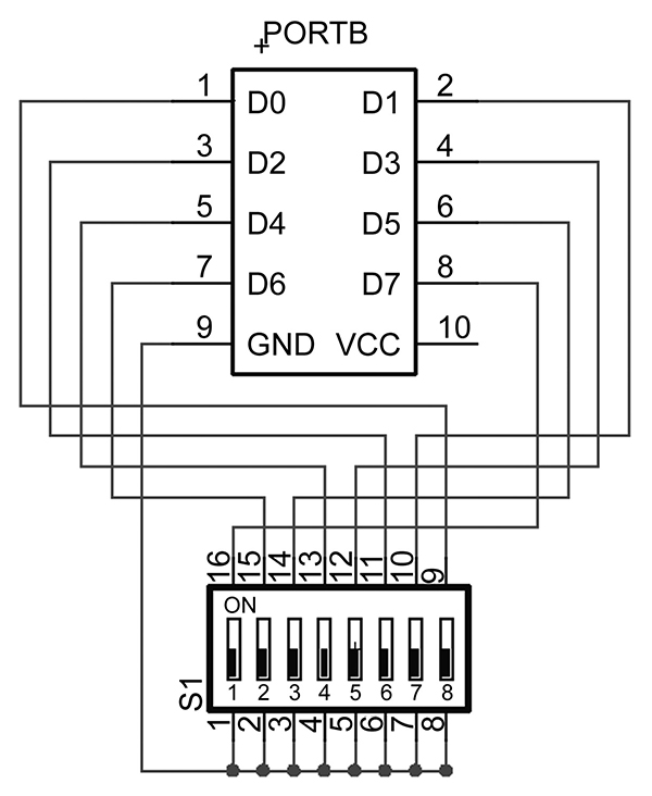 |
| FIGURE 3. PORTB to eight bit DIP switch |
Using the LED wiring from the last project, add the switch as in Figures 1 and 3. You may refer to Figure 3 from Workshop 1 to see where port B is (you can download Workshop 1 from www.nutsvolts.com or www.smileymicros.com).
The LEDs will display the state of the switches. And, if you are paying attention, you’ll say, ‘Hey wait a minute, these switches and lights are reversed.’ And you’ll be wrong. PORTB pins are pulled up so when nothing is on them they are at Vcc and the associated LED is lit. Turning the switch ‘on’ pulls the pin to GND, thus the associated LED turns off. Okay, you think it’s crazy that one kind of on means off, but as we’ll see in detail later, we define what voltages are true or false or on or off any way we want to. A lit LED can mean either off or on, it’s a choice not a law. Think about the logic behind this since it isn’t nearly the most confusing thing we’ll eventually see. Next month, we’ll look at some more C syntax and learn how to get a Butterfly to talk to a PC. NV
Joe Pardue has a BSEE and operates www.smileymicros.com from the shadows of the Great Smokey Mountains in Tennessee. He is author of Virtual Serial Port Cookbook and C Programming for Microcontrollers
Links
The datasheet for the Atmel 8-bit AVR Microcontroller with 16K bytes In-System Programmable Flash can be found at Atmel.com but here is a direct link to the download: ATMega169 datasheet.pdf
Downloads
Smileys Workshop 200810 (Workshop 3 files)