I’m designing and building two identical stereo amplifiers for a stereo system, and needed a good speaker protection and muting circuit. Here’s what I did ...
A speaker protection and muting circuit is installed between a DC coupled audio power amplifier output and the speaker. Its main purpose is to disconnect the speakers as soon as a large DC voltage that can damage the speaker is present at the output of the amplifier.
This can happen when the amplifier is malfunctioning. The most common failure scenario is when one of the output device fails short, resulting in the full DC rail voltage being delivered to the output terminals. Besides defending speakers against output device failure, the circuit also eliminates “turn-on thump” by connecting the speakers only after the power amplifier has been powered on and enough time has passed to allow the DC offset to stabilize.
Speaker protection and muting schematics have been around for a long time, but it seems to me that one configuration hasn’t been taken into account. I’m talking about using an optical coupler right after the low-pass filter at the front end of such a design. From my days working in telecom, I remembered that the GaAs infrared LEDs used in optical couplers need a small amount of current to open — especially when higher speed is not needed.
So, I will build this using an optical coupler. A Google search shows at least one device that fits the bill: a dual channel bi-directional optical coupler that has a photodarlington (LDA210) at the other side, making the current gain high. Per the datasheet (available with the article downloads), it has a typical current gain of 8,500% and the LEDs require about 75 µA to open.
Using a bi-directional optical isolator has a couple of obvious advantages. Aside from the galvanic isolation, there is also perfect symmetry without the need for a differential power supply or a floating reference like other schematics are employing. After testing different configurations, I came up with the schematic in Figure 1.
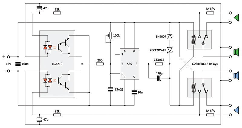
FIGURE 1. Schematic of the circuit.
The 555 timer takes care of the muting part; it’s set at two seconds with the 100K ohm (55.1K ohm) trim pot and the 33 µF tantalum capacitor. I like to use tantalum capacitors in timing circuits because the value of their capacitance has good stability over time.
A different muting time can be calculated using t = 1.1*RC, where R is the 100K ohm trim pot and C is the 33 µF (t) capacitor. The 555 timer has a maximum of 200 mA current capability sinking or sourcing through pin 3, making the schematic even simpler.
The 133 ohm/0.5W resistor with the 470 µF capacitor is a power-saving circuit. When the circuit is first powered up, for a moment — until the 470 µF capacitor is charged — the current drawn with a 11.37V DC power supply will be about 84 mA. After the capacitor is charged, it drops to 42 mA.
One would think that this power-saving circuit will make the release time of the relays longer, but, in fact, the release time is about the same because the voltage across the coils drops from the maintenance voltage of 6.5V and not from 11.37V. The 11.37V is from a 12V power supply with a diode in series. Of course, the circuit works with 12V equally well.
The way that it works is simple: If a positive or negative DC voltage is present at the output of one of the power amplifiers (or both), the corresponding 47 µF bi-polar capacitor begins charging through the 22K ohm resistor until it reaches the threshold of 1.2V. At this voltage, the corresponding infrared LED will open, and the collector-emitter of the Darlington will open as well, shorting the 33 µF capacitor to minus through the 200 ohm resistor.
When the voltage across the capacitor drops below 1/3 of the supply voltage, the output (pin 3) of the 555 timer goes high, and the relays disconnect the speakers and connect them to the amplifier’s ground.
The amount of time it takes for the relays to disconnect the speakers depends mainly on the time constant of the RC low-pass filter at the input. The table in Figure 2 shows the disconnecting time with DC voltages from the threshold (1.2V DC) up to 50V DC. In case you were wondering, I always discharge the capacitor before each measurement.
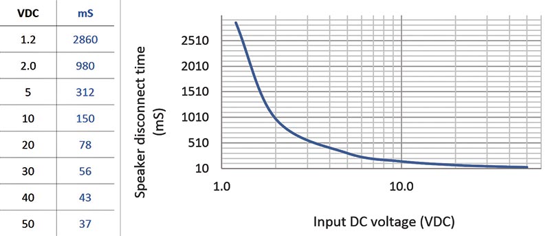
FIGURE 2. Graph with delay times.
I designed this for my 40W amplifiers. The maximum output voltage on an eight ohm load before clipping is about 18V RMS, and is linear between 20 Hz and 20 kHz. The input of the amplifier has a 1 µF capacitor with a 100K ohm resistor to ground, making a low-pass filter with an fc of 1.59 Hz. Leaving the voltage level at 18V RMS at 20 Hz, I lowered the frequency until the relays were turned off. The relays turn-off frequency is 3 Hz with a 17.58V RMS with the 22K ohm/47 µF low-pass filter.
This is a good compromise. I don’t think a 3 Hz signal is something common nowadays in recordings, but I imagine that a warped vinyl record can generate a very low frequency (maybe even 3 Hz) unless there is a low-pass filter in the signal’s path.
Two Separate Inputs or One Common Input?
The reason I’m using two separate inputs is because with one common input (two resistors feeding one capacitor), the DC voltage is halved, making the disconnect time about twice as long.
Also, there’s a very remote possibility of both channels of the amplifier failing at the same time: one putting out the positive, and the other the negative rail DC voltage. In this case, if the protection circuit uses a common input, the two DC voltages cancel each other rendering the circuit useless.
For the input filter, I’ve also tested a second order cascaded filter, but it turns out that, in fact, it’s slower because the capacitors are charging one at a time. This is a case where simpler is better.
Relays
There are a good number of kits and schematics for speaker protection and muting one can find. However, most of them have a common issue: The way the speaker is wired to the relay does not protect the speaker in case of amplifier malfunction.
In most of these circuits, the relay opens when the DC voltage is present, but the arcing will weld the contacts together, and the energy from the capacitors in the power supply will pass through the speaker’s coil to ground. In fact, the arcing could last seconds as there is a “ping-pong” match between the speaker’s inductive reactance and the capacitors in the amplifier’s power supply.
To really protect the speaker, the relay used should have an SPDT contact that puts the speaker to ground as we can see in the circuit. This arrangement will take the arcing to ground and not through the speaker, forcing the fuse to blow.
Of course, there are relays designed for large DC voltages and currents, but usually those are expensive. There are relays with magnets placed close to contacts that will break the arcing, or with the contacts sealed in an inert gas; relays with contacts with a higher melting point (like tungsten) doubled by silver contacts for better conductivity; or multiple contacts in series, etc.
Or, we can use two fast solid-state relays (fairly expensive) controlled by the circuit presented here to disconnect both DC rails when DC voltage is present at the output of the power amp. All these could be employed, but they will end up doing the same thing as the G2R relays used.
PCB Design
For drawing the schematics, I use VISIO Technical. I did the PCB (printed circuit board) design on double-sided FR4 with 2 oz of copper for higher current capability. The software used is Pad2Pad and can be downloaded from the Pad2Pad website (https://www.pad2pad.com).
An external trace of 1.00 mm width with 2 oz copper can carry 3A. On my board, the high current traces are wider and doubled as you can see in Figure 3 and Figure 4.
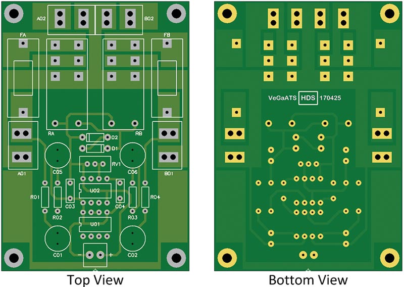
FIGURE 3. PCB artwork, top and bottom views.
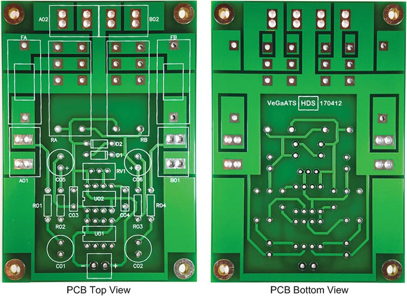
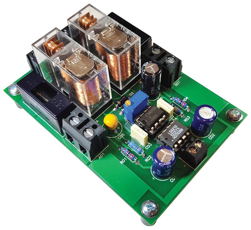
FIGURE 4. Photo of PCB, top and bottom.
AC Detecting
Following the same principle, an AC detecting circuit can be inserted (as shown in Figure 5) for applications where there is not 12V DC that falls fast enough to disconnect the load before the output of the amplifier goes through the sudden large voltage swing that can stress the speakers and the ears.
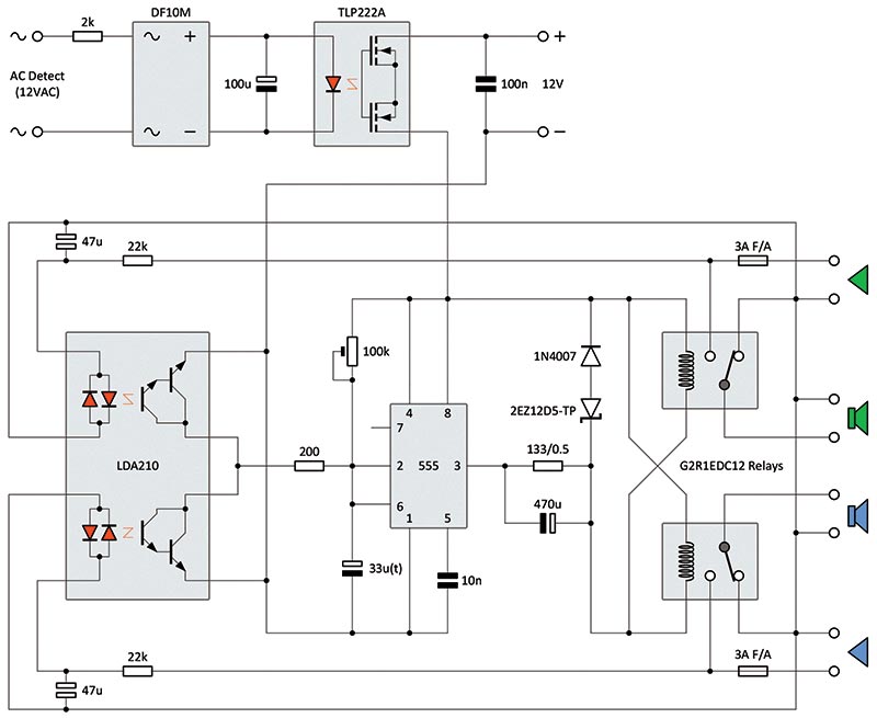
FIGURE 5. Schematic of the circuit with AC detection.
The TLP222A is a solid-state relay (SSR) used in series with the 12V supply. It stays open (2.0 ohms max) if there is AC voltage at the input of the DF10M bridge rectifier. Per its datasheet, the time taken by the SSR to open and cut the voltage to the protection circuit is maximum 0.5 ms. The maximum release time of the G2R relay is 5 ms.
For different AC voltages, the value for the 2K ohm resistor must be changed to limit the current through the LED inside the SSR to a typical 7.5 mA. In the datasheet, the recommended range for the current for the LED is from 5 mA to 25 mA. The test I did was for 12V AC and the current-limiting resistor was 2K ohm.
Conclusion
This circuit will protect speakers in case of amplifier malfunction. When the amplifier gets repaired, it’s recommended to replace the relays also; that’s because the contacts will be damaged more or less, depending on how much current and how long the arcing occurred. This is still cheaper than a pair of special relays.
For AC inductive loads (cosq = 0.4), the contacts of the G2R high capacity relay used in this design are rated for 16A and 180V.
For DC resistive loads, the contacts are rated at 16A and 30V. For DC inductive loads, refer to the graphics under Engineering Data in the G2R relay datasheet.
As it is, this circuit works well for my 40W power amplifier. It will probably work for amplifiers with up to 100W of power.
For amplifiers with more power, different relays will have to be selected.
As I said before, this is important, and it will save your expensive speakers if the correct relay is chosen. NV
Parts List
| COMPONENT |
VENDOR |
VENDOR PN |
QTY |
| 154 ohm 0.5W |
Mouser |
603-MFR50SFTE52-154R |
1 |
| 200 ohm 0.25W |
Mouser |
603-MFR-25FRF52-200R |
1 |
| 22K ohm 0.25W |
Mouser |
603-MFR-25FRF52-22R |
2 |
| 100K ohm trimpot |
Mouser |
652-3296W-1-104LF |
1 |
| 10 nF film |
Mouser |
594-2222-370-36103 |
1 |
| 100 nF film |
Mouser |
594-2222-370-36104 |
1 |
| 33 µF (t) |
Mouser |
581-TAP336K025SCS |
1 |
| 100 µF electrolytic NP |
Mouser |
667-ECE-A1EN101UB |
2 |
| 470 µF electrolytic |
Mouser |
667-EEU-FR1E471Y |
1 |
| 1N4007 |
Mouser |
512-1N4007 |
1 |
| LM555 |
Mouser |
926-LM555CN/NOPB |
1 |
| LDA210 |
Mouser |
849-LDA210 |
1 |
| 2A fast-acting fuse |
Mouser |
576-0217002.HXP |
2 |
| RTD34012 relay (16A) |
Mouser |
655-RTD34012 |
2 |
| 3.5 mm terminal block |
Mouser |
538-39357-0002 |
1 |
| Fuse holder PCB mount |
Mouser |
534-4527 |
2 |
| 4-position 7.5 mm fixed terminal block (15A) |
Digi-Key |
ED1569-ND |
1 |
| 2-position 7.5 mm fixed terminal block (15A) |
Digi-Key |
ED1567-ND |
2 |
Downloads
What’s in the zip?
Datasheet
Parts List
Schematic
PCB File