Instrument Your Favorite Sporting Goods!
Is it a bird? Is it a plane? No, it's a computerized Frisbee with a BASIC Stamp! In this simple project, I will show you how to make an ultralight, but easy-to-assemble, acceleration recorder that you can use to measure the dynamics of small vehicles, much like the "black box" aircraft flight recorders.
CHARTED DATA.
Frisbee Background
I wanted to understand the aerodynamics of a Frisbee by taking in-flight measurements of lift and drag. Although Frisbees (the name — a corruption of that of William Frisbie, a Connecticut baker whose pie tins formed the inspiration for flying disks — is a trademark of Wham-O, Inc.) are very familiar objects, their impressive flight performance is only documented with a handful of published studies and wind-tunnel measurements. Some background can be found at http://mae.engr.ucdavis.edu/~biosport/frisbee/frisbee.html. By taking in-flight measurements, I would understand the changing aerodynamic forces throughout a free flight.
The challenge was to make a super-lightweight and compact instrument package. The accelerometer and the microcontroller were tiny enough, but the power supply presented a problem. Two lithium button cells (CR2032) in series can provide 6V, but only about 10 mA of current. This is, however, just enough to run a BASIC Stamp II (although not enough to run other faster microcontrollers like the BS2-SX or a BASICX-24.) The accelerometer draws just a few milliamps at most.
The circuit itself is very simple, as the accelerometer interfaces very easily with the microcontroller. Given 5V, it spits out two square wave signals, which are pulse-width modulated (PWM) by the acceleration in two axes. If it senses zero-g, if that axis of the accelerometer (there are two) is horizontal, or if the device is in free-fall, the duty cycle of the output is 50%. The duty cycle increases by 12.5% for each "g" of acceleration, up to two in each direction. So, all the circuit does is measure the pulse lengths on the two accelerometer axes, record those numbers, and read them out afterwards. Simple!
Choice of Accelerometer
The best device to use is the Analog ADXL202 (if you can still find them). The accelerometer itself is a tiny surface-mount device, but it is conveniently sold on an evaluation board. This unit used to be sold by Parallax (the makers of the BASIC Stamp), but they have replaced it in their catalog with a MEMSIC unit, which is a little smaller.
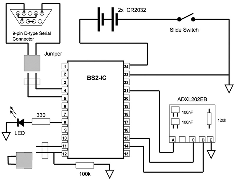
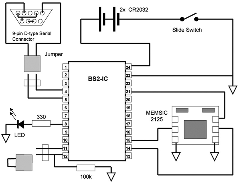
There are three big differences between these devices. The Analog device uses a bending beam to sense acceleration and can be tuned to optimize bandwidth against signal-to-noise (two 0.1 mF capacitors and a 120K resistor on the board set the pulse width and sensing bandwidth correctly for this application, the PWM period being about 1 ms), and draws only about 0.5 mA. The MEMSIC unit uses a different sensing principle, measuring the "gravity-driven" convection of heated air. It, therefore, has an intrinsically slower response, and draws more current — about 4 mA. The evaluation board sold by Parallax has the PWM period fixed at 10 ms — giving great accuracy, but a slow response. For convenience, I give construction details (Figure 1 A, B) for both kinds of accelerometer, but the ADXL202 is better.
A.
B.
FIGURE 1. Circuit diagram for the ADXL202 (A) and MEMSIC 2125 (B) accelerometer options.
Construction
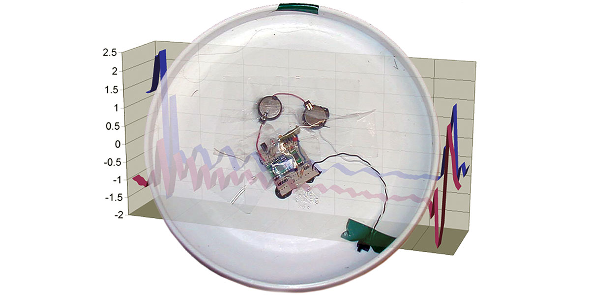
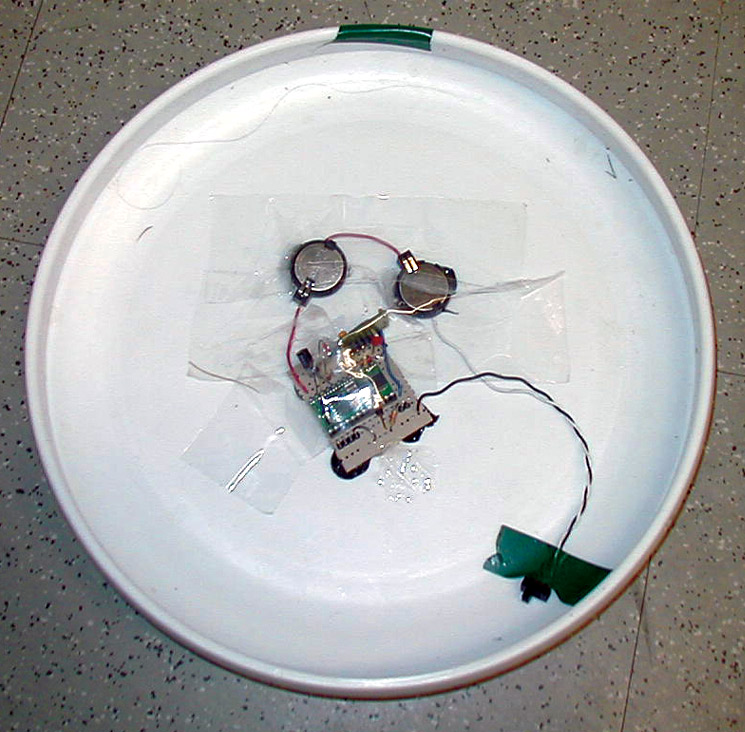
Most of the lift on the Frisbee comes from its top, so it was safe to mount the circuit on the underside of the disc where it doesn't greatly affect the airflow. I put clear plastic tape over much of the circuit after assembly to smooth the airflow and minimize any drag effects.
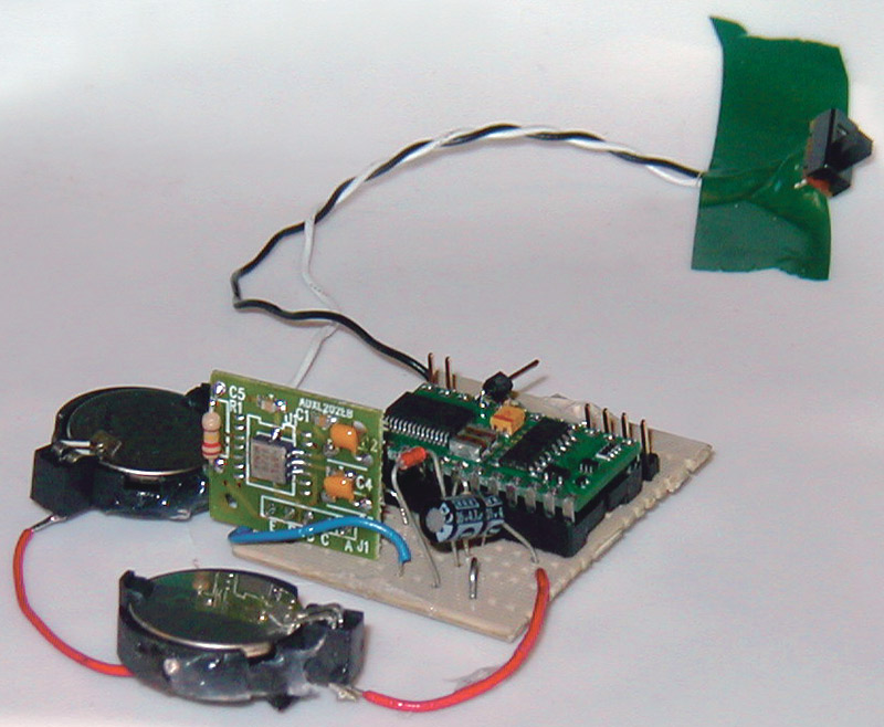
I assembled my first circuit on a piece of stripboard for sturdiness, but, since there are actually very few connections, it is easier (and lighter) to make individual wire connections to an IC socket. Complete with batteries and switch, the circuit board version weighed around 28 g; the bare-bones version was under 20 g (Figure 2). These weights are minimal when compared with the 175 g weight of the Frisbee — less than 20%.
A.
B.
FIGURE 2. Arrangement of parts on the underside of the Frisbee (A) with a close-up of the ADXL202 version, built on a small circuit board (B). The two circles are the lithium button cells. Green chip is the BASIC Stamp, small green board is the ADXL202EB.
I added an LED, just to be able to see what the program was doing. The program strobes it rapidly when it is taking data, and goes on constantly afterwards when the code is reading out the data. A dark LED is a sure sign that something isn't working.
The other items in the circuit are the two cells connected in series (I gave them a few inches of wire, so that the cells could be placed around the center of the Frisbee, balancing it) and a slide switch. Placing this near the rim of the disc meant the circuit could be turned on just as I threw the Frisbee. I mounted all the items on the underside of the disc with silicone adhesive (Figure 3). It is important to mount the accelerometer as close to the center as possible. One accelerometer axis should be along the spin axis of the Frisbee.
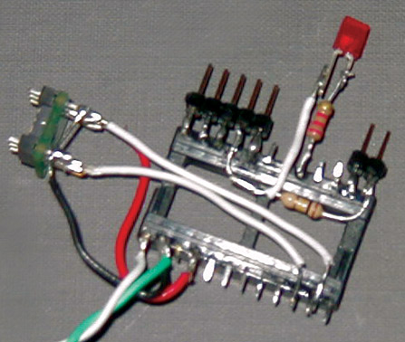
FIGURE 3. Close-up of "skeleton" boardless construction around the 24-pin IC socket, with the MEMSIC accelerometer on the left. Note the header pins for the realtime/sample-and-readout switch and serial connector.
One approach, if you have a BASIC Stamp breadboard, is to download the program to it, and transfer the chip to the Frisbee set-up. However, if you want to tweak the program, this can be tedious and tends to bend pins on the Stamp. What I did was to make a separate cable to link a nine-pin serial connector to pins 1-4 on the Stamp via a small header (Figure 4).
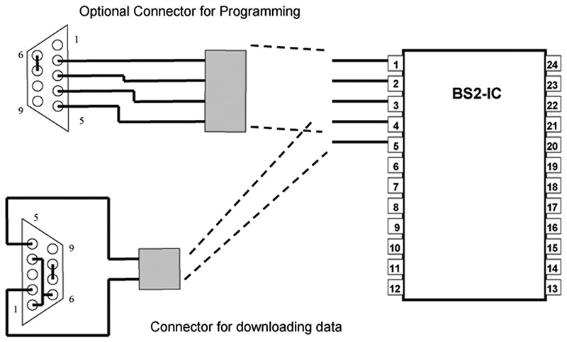
FIGURE 4. Serial connection details.
Because the serial handling for downloading the data from the unit after flight is easier, the data output is on pin 5 (P0) — a two-wire header (or two pins of a five-pin) connects pin 4 (ground) and pin 5 to a serial conector. This connector is easily attached after the flight.
The Program Operation
The BS2 has a 2K EEPROM, which must contain the program, as well as any data. The program itself is quite short and leaves about 1,600 bytes of EEPROM memory spacefor data storage. The BS2 reads the accelerometer with the PulseIn command, which returns the length of a positive PulseIn the PWM output stream, measured in units ("ticks") of two microseconds. (I found that using two PulseIn commands reduces noise for the ADXL202, although for the MEMSIC, this slows the execution speed too much.)
Now, numbers like the PulseIn output are 16-bit (two byte) words. To store each reading for each of the two accelerometer axes would not only require two EEPROM write operations (which are slower than most of the BS2 operations, like arithmetic) and would require two of the precious bytes of EEPROM. But, adequate precision (about 2%) for this application can be had with only eight bits of data. The ADXL202 output is easily scaled to an eight-bit range (0-255) by subtracting about 80 from the output. The much slower MEMSIC device has a longer pulse length, and so the output, in ticks, needs to be divided by a factor of 10, as well as subtracted — you might need to fine-tune these numbers yourself. The program reads the sensors, performs this conversion, and stores one byte per reading in EEPROM.
Once the program has finished sampling (about 12 seconds for the ADXL202 version — long enough for anything except a record-breaking Frisbee flight!), it reads out the data to the serial port as two columns of numbers separated by a comma. The two accelerations are reported as eight-bit integers. To convert to real accelerations, I read the data into a spreadsheet program and convert according to a formula such as:
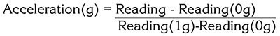
where the 1 g reading is for that axis of the accelerometer pointed downwards, and the 0 g reading for the orthogonal axes.
For testing/debugging and getting these calibration readings, I found it easier to have the BS2 read data out in real time to the serial port, rather than storing and reading it out later. Rather than reprogramming the BS2 each time, I switched between the two modes with a jumper cable that acts as a switch on pin 12 — you could easily install a switch, although this might be heavier than a jumper. To simplify the wiring, I took the lazy approach of supplying the 5V for this test from pin 11; pin 12 is pulled low by a 100 K resistor to ground, unless pins 11 and 12 are linked.
The data can be captured by setting up a terminal program (Hyperterminal is installed on most Windows PCs) — the settings have to be 9600 baud, eight data bits, one stop bit, no parity, and no flow control. The data can be captured to a text file, converted as above in a spreadsheet program, and then graphed for analysis.
Making Sense of it All
The 800 readings in 12 seconds correspond to about 65 two-axis samples per second. (Using the MEMSIC device gets only about 30 samples per second, although the record lasts longer). You can get the sample rate by watching the LED to determine the exact time of the record and dividing by 800.
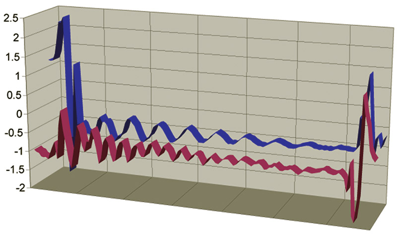
The record shows a violent disturbance as the disc is thrown. The axial accelerometer channel shows an almost constant time-average value of about -0.8 g, indicating almost level flight up to the end, although there are a lot of oscillations added from the wobbling of the slightly imbalanced Frisbee just after the throw. The radial accelerometer also shows a -0.5 g offset, due to the fact that the accelerometer isn't quite dead-center, and so it records a constant offset due to the centripetal acceleration, proportional to the square of the spin rate. The radial signal has a spin-modulated component about this mean, due to the accelerometer axis alternately being along and against the drag force (actually, the disc flies with a slight nose-up "angle of attack", so what is sensed here is drag force and a bit of lift that is inclined backwards). The period of this oscillation directly indicates the spin rate of the Frisbee, which a careful study shows to be decreasing from about 6.5 to about 5.5 revolutions per second.
Interpreting these results in quantitative aerodynamic terms is, of course, an involved business, but just looking at the graphs gives you a good idea of what is going on. Analyzing data like this might make a good science fair or other project.
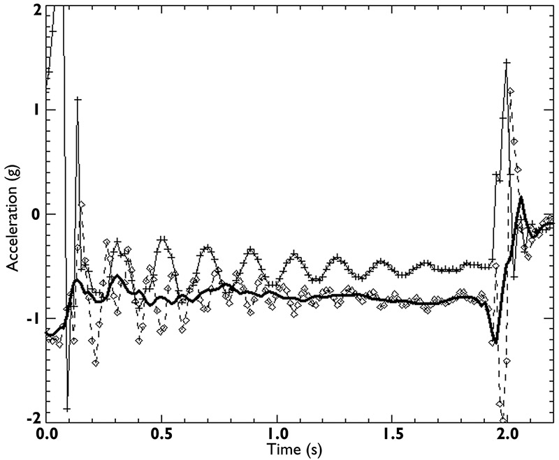
FIGURE 5. Flight results (see text). Diamonds show the wobble-modulated axial (lift) accelerometer, with a solid line showing smoothed data. Crosses are the spin-modulated radial (drag) accelerometer. Accelerations go out-of-range for the throw at the beginning and the impact at the end.
Other Ideas
You could use this sort of circuit on a radio-controlled airplane, car, or boat. A similar circuit could be used for a model rocket, although the g-loads will be much larger than the ±2 g range of the ADXL202, so a different accelerometer would need to be used — the ADXL210 is similar to the 202, but with a 10 g range. For higher accelerations, you may need to use more sophisticated circuitry with an analog-to-digital converter, as PWM outputs are not typical for such high-g devices.
You could also try all kinds of variants on a circuit like this — photodiodes to measure the position of the sun and hence the "wobble" on the Frisbee or pressure sensors to measure the suction that causes the Frisbee's lift. Maybe infrared or ultrasonic rangers could tell you the altitude as a function of time. Happy flying! NV
PARTS LIST & VENDOR INFORMATION
24-pin IC Socket
BASIC Stamp 2 (Parallax BS2-IC or Jameco #130892)
330 ohm 1/4W Resistor
Red LED
100K 1/4W Resistor
Slide Switch
2x Two-pin Header and Connector
2x CR2032 Lithium Button Cell
2x Button Cell Holder (Jameco #38535)
Nine-pin Female D-type Socket
MEMSIC 2125 (Parallax #28017) or Analog ADXL202EB Accelerometer
(Optional, for programming the Stamp in-situ)
Replace one of the two-pin headers above with a five-pin header and add one four-pin connector and one nine-pin female D-type.
www.jameco.com
www.parallax.com
See also
www.analog.com
www.memsic.com