In the 1950s and ‘60s, Popular Electronics and other magazines carried ads for strange looking machines called Geniacs and Brainiacs. The ads claimed they were “electric brains” that could play Tic-Tac-Toe and NIM. A while ago, I bought several sets on eBay and would like to share my experiences of learning about them and my sometimes frustrating — but successful — efforts to get them to work.
Figure 1 shows a typical Geniac advertisement from a 1958 issue of Popular Electronics. It was $19.95. The concept was simple enough. It had six giant 4.5” diameter rotary switches that could be configured in a zillion different ways to help youngsters learn how electrical circuits could solve logic problems and play games such as Tic-Tac-Toe. Ten flashlight bulbs were mounted across the middle to indicate and guide the outcome of the games. It included a manual that described over 100 different “machines” to build.
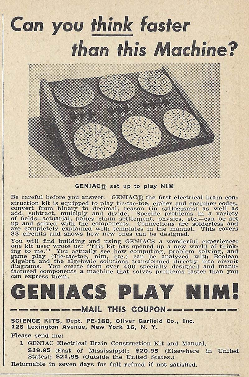
FIGURE 1. Geniac sets were heavily advertised in electronics magazines in the 1950s and ‘60s. Only $19.95 and no soldering required. Over 30,000 sets were sold.
MASONITE SWITCHES
The Geniac rotary switches were made of hard Masonite as seen in Figure 2 and had metal screw contacts underneath to conduct current to the flashlight bulbs.
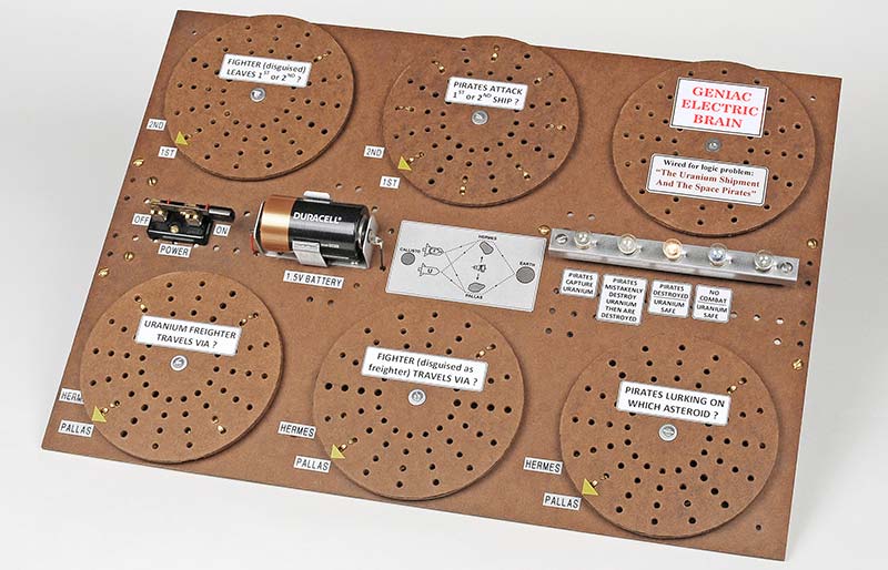
FIGURE 2. The large Masonite rotary switches enabled many different configurations including logic problems such as “The Uranium Shipment and the Space Pirates,” shown here.
Each switch had 64 holes to mount a number of brass “jumpers” and the 12” x 16” backboard had an equal number of holes to mount dozens of mating “contact screws.” Please see Figure 3.
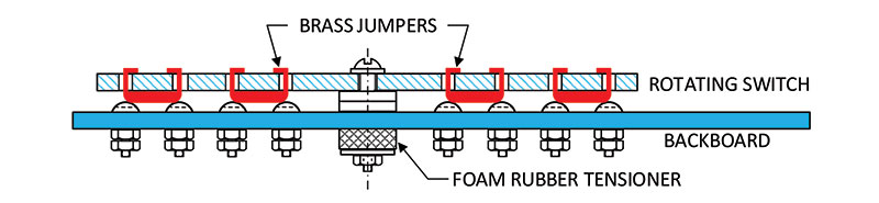
FIGURE 3. The rotating switches used brass “jumpers” to make contact with 6-32 screw “contacts” mounted in the backboard.
The configurations were easily changed by simply moving the 6-32 screws to different holes in the backboard. Interconnections were made on the backside, with insulated wires looped around the screws and secured by nuts. I’ll talk about the jumpers and contact screws in greater detail later on. And about the problems they had.
THE START OF MY JOURNEY
About a year ago, I happened to see a pair of vintage Geniac sets for sale on eBay. Then, I also found a Brainiac in a colorful box. To make a long story short, I bought all three and started on a very bumpy four month journey to get the sets to work. First of all, I read over the manual and settled on wiring up an interesting logic problem called “The Uranium Shipment and the Space Pirates.” Please refer to Figure 2 again. It used five of the switches to enter various scenarios for the Pirates, a Fighter ship, a Uranium Freighter, and two asteroids. The four lamps shown in Figure 4 indicated the outcomes of the scenarios, such as “Pirates Destroyed, Uranium Safe.”
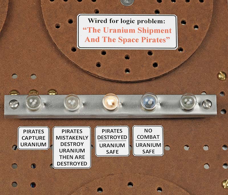
FIGURE 4. There were 32 possible scenarios using the switches. The four lamps indicated the success or failure of transporting the Uranium to safety.
THE LOGIC WAS NOT AS SIMPLE AS IT LOOKED
Figure 5 graphically illustrates that the logistical task was to safely move a valuable load of Uranium by Freighter from Jupiter’s moon Callisto to Earth. There were two routes to take: either via Hermes or Pallas. However, the wild card was that an all-powerful Fighter ship — cleverly disguised to look like a Freighter — could be used to protect the actual Uranium Freighter.
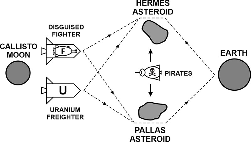
FIGURE 5. The wild card in the game was to decide whether the all-powerful disguised Fighter should lead or follow the Freighter in order to destroy the Pirates.
To further complicate things, the Fighter and Freighter could either travel on the same route or separately, and if they went together, you had to select in what order they would leave Callisto.
The final complication was that the Pirates could be lurking on either asteroid. Furthermore, if two ships approached them, the Pirates could gamble that the first Freighter was actually the disguised Fighter and let it go by, then wait for the defenseless Uranium Freighter to fall into their trap.
This supposedly simple logic setup had a grand total of 32 different states and four outcomes to keep in mind. Made your head spin!
THE BACKBOARD WIRING
Figures 6 and 7 show the diagram from the manual and the actual wiring of the Pirate game on the backside of the Masonite “backboard.” You might notice that my many years in Aerospace were reflected in how I wired the backboard. For me, it had to look neat and be tied up with lacing cord. I couldn’t help myself.
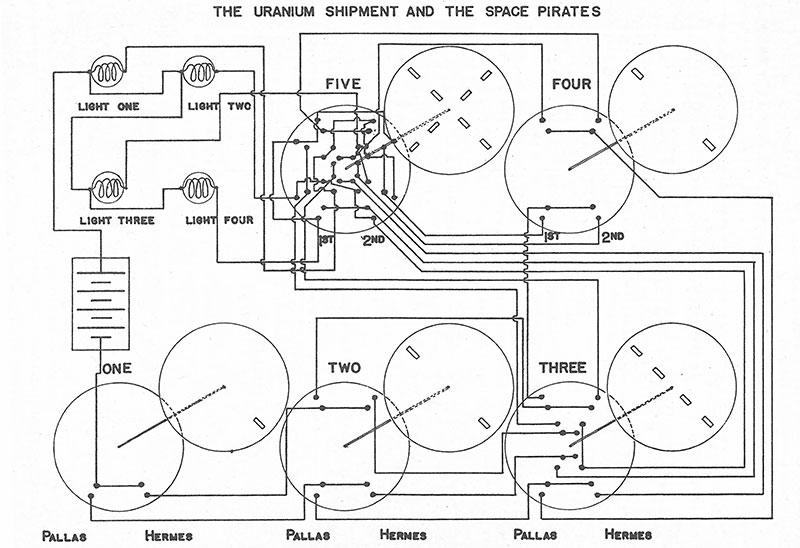
FIGURE 6. “Backside” schematic of the Pirate game from the manual. Notice I changed the wiring layout of switches #3 and #5 in Figure 7 to reposition all contacts to the more reliable outer ring.
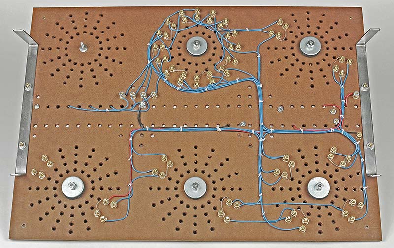
FIGURE 7. The various circuits used #22 wire to interconnect the 6-32 contact screws and lamps. I couldn’t help myself making it look neat instead of a rat’s nest.
ALL WAS NOT WELL
When I first put the Pirate game together (back in Figure 2) and tried to save the Uranium, all was not well! When the switches were rotated, the contacts didn’t always make good connections and the appropriate lamp would not get any voltage.
Sometimes I could use my fingers to press down on parts of various switches to make contact and light the lamps. Many times, no lamps would come on at all and I would get confused, frustrated, and irritated! But I persisted.
TRYING TO FIX THE PROBLEM(S)
Problem 1: The screw heads were not all exactly the same height.
Possible Fix: I glued a disk of 100 grit emery to a flat disk of aluminum and sanded off the high spots on the screw heads.
Results: The operation of the game was no better. Darn!
Problem 2: The brass jumpers were not all the same height.
Possible Fix: I used the same disk of emery to gently sand them, since they were made of very thin brass.
Results: No better again! Darn again.
Problem 3: I checked the flashlight lamps to make sure one wasn’t burned out.
Possible Fix: Amazingly, one WAS burned out. It looked okay but the tiny filament was open.
Results: Replaced lamp. Still no better operation. Double darn!
Problem 4: The lamps flickered sometimes when I wasn’t even touching the switches.
Possible Fix: I applied voltage directly to each socket and found that the lamps tended to loosen up all by themselves.
Results: Double-checked that all lamps were tight before each test.
Problem 5: Perhaps if I traced out the circuitry, I could locate the really poor connection(s) and know exactly where to press down on the switch(es) to make contact.
Possible Fix: I spent two days rotating switches to different positions and using a VOM to locate exactly where the poor connections were.
Results: One time the bad connection would be on Switch #5, then on Switch #3, then back on #5, etc. Very frustrating!
Eventually I just threw up my arms!
SCREW HEADS OR WIPERS?
Over the approximate 10 year life of Geniacs and Brainiacs, two types of contacts were used to make the rotating connections. Figure 8 shows the two competing contact schemes: screw heads and spring wipers. Both had their problems.
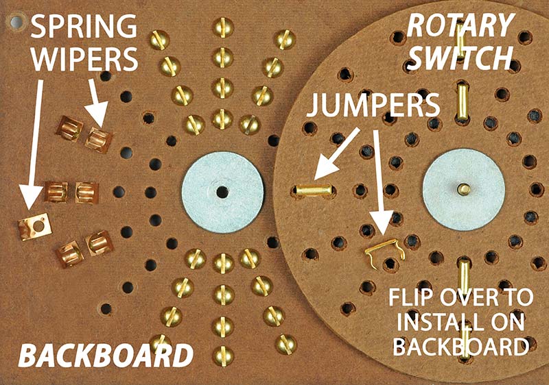
FIGURE 8. Disassembled view of the rotary switch, showing two styles of contacts: screw heads and spring wipers. Both styles were used in various sets over the years. Neither were reliable.
Both also used the same little brass jumpers to wipe across the contacts. The jumpers were installed up through the underside of the Masonite disks and their little tabs were bent over on top to hold them tightly against the Masonite. Please refer back to Figure 3 for a better visual.
IDENTIFYING THE CORE PROBLEM
Again referring to Figure 3, I concluded that the Masonite switches were just not mechanically precise enough for four fixed jumpers to make simultaneous contact with eight fixed screw heads. If just one screw head was a little too low or a Jumper was slightly canted, contact was lost.
The spring wipers were a little better but they also had problems achieving the precise alignment required to be reliable. I have read that other builders of Geniacs and Brainiacs had similar problems. One user I heard from said it all, “It was a box of well-intentioned junk.”
LET ME INTERRUPT FOR A MINUTE
I imagine that some of you might have built a Geniac or Brainiac at one time and had first-hand experience with them. What games or logic problems did you try and how did it go? Do you still have one tucked away in a closet? I would certainly love to hear from you.
Perhaps you would consider saying a few words in the COMMENTS section on the website page for this article. Thanks!
A SUCCESSFUL SOLUTION
Figure 9 shows the successful solution I devised that works great for the Pirate game.
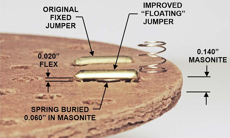
FIGURE 9. My solution was to add tiny springs under the jumpers so they would press against the screw heads. The Pirate Game in Figure 2 had 18 springs and it worked every time!
My idea was to make the jumpers “floating” instead of “fixed.” I did this by installing tiny springs directly under the jumpers, in little pockets in the Masonite. Then, the jumper tabs on the top were bent over such that the jumpers were not pulled up tight against the wood. This gave them a little room to flex up and down. Actually, I milled little pockets in all the Masonite switches for the springs to drop into. In operation, that small amount of flexing allowed the jumpers to press down against any uneven screw heads and make good contact. SUCCESS AT LAST!
Triumphantly, I spent several hours playing the Pirate game and learned that it was far better to be a Fighter pilot than a sneaky Pirate.
TIME TO MOVE ON TO THE K-20 BRAINIAC SET AND NIM
The Brainiac I bought on eBay was a K-20 and the box was a sight to behold; refer to Figure 10. Brainiacs came in two popular sizes: the K-20 having four switches and the K-30 having six.
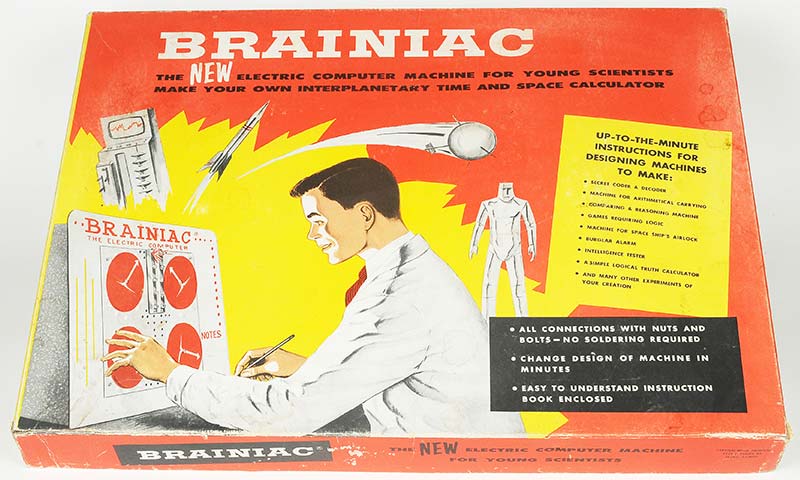
FIGURE 10. Look-alike Brainiacs arrived in 1957, after a contentious splitting up of the two original Geniac developers. I found a K-20 set on eBay.
I chose to wire up the Brainiac to play NIM using the diagram in the manual. As you might know, NIM is a very old game and typically consists of a number of piles of things like stones or coins.
For example, it could start with four piles of eight stones, although the piles don’t really need to have an equal number of stones. Each player, in turn, removes one or more stones from any one pile. The other player then does the same, removing any number of stones from any one pile. The person who picks up the last stone wins the game. It sounds simple, but it’s not.
There are some underlying mathematics that can vastly increase your chances of winning. The schematic in the manual shows how to wire the Brainiac so it always makes the best moves, i.e., the game is stacked against you unless you know the tricks. Hint: Don’t let Brainiac make the first move.
I HAD A CRAZY IDEA
The manual specified four piles: pile A=1, B=2, C=3, and D had 4. To play a typical game, the first player might rotate switch A to 0, leaving nothing. This action, in turn, would light up one of five flashlight bulbs.
The manual explained that depending on which bulb was on, the player would then be required to execute the machine’s turn by physically rotating a certain switch a certain amount.
And so it went. Player, machine, player, machine, player, machine, etc., until the last switch was rotated to zero and that player was declared the winner. It wasn’t all that exciting because the player had to physically make all the moves. But it was fun to try to outsmart the machine.
That’s when I had a crazy idea! Why not make the switches move themselves? That way, the player could make a move, then the machine would make its move, etc.
I couldn’t resist jumping on this idea, so I mounted four RC servo motors underneath the backboard and connected them to the shafts of the Masonite switches. An Arduino was also added to put out the correct pulses to control the servos.
Figure 11 shows the end result and it worked beautifully. Zip, zip, zip! It was the classic man against machine! Of course, I wasn’t satisfied with just adding servos. I also had to include a digital sound track to give a “voice” to the game. Plus, a wooden box was needed to give it a finished look and to house all the extra goodies.
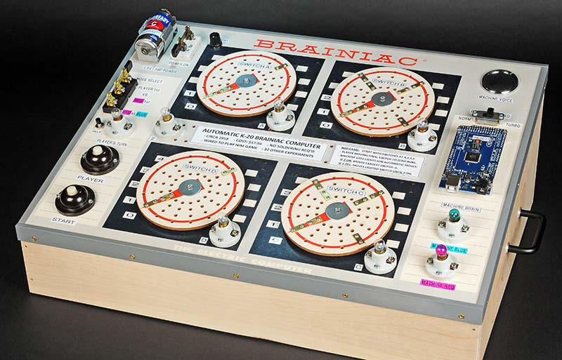
FIGURE 11. The Brainiac was wired to play the game of NIM. I added four servo motors underneath to rotate the switches so the machine could make its own moves.
Figure 12 is a close-up of one of the servo motors underneath. The original Brainiac Masonite switches were not made to be driven from below. They simply pivoted around long screws. So, I fabricated and installed 1/4” drive shafts to each switch to connect them to the servos.
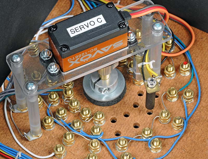
FIGURE 12. The servos below were attached to the switches with new drive shafts. The Arduino enabled the machine to play a game against itself in 6.2 seconds.
RED MACHINE VERSUS BLUE MACHINE
However, the coolest thing was that now the machine could theoretically play a game of NIM against itself. Zowie! So, I sat down and programmed the Arduino to play NIM with the undefeated Red Machine versus the Blue Machine. The program used the lamps to guide the moves, just like before. The Arduino was only there to move a certain switch a certain amount, according to which lamp was on or off.
The first time I tried it, I hit the Start button and the switches and soundtrack starting flying. “Red, Blue, Red, Blue, Red ... Winner, Winner, Winner!” It took just 6.2 seconds to declare the Red Machine the winner. I was gassed.
Of course, I realize the whole idea with the servos was a stretch, but I had fun with it. You can see a video at www.youtube.com/watch?v=LfWWqfK2_FE of the machine playing NIM against me and also against itself. (Please note there is an “underscore” between the 2 and FE in the link above.)
GENIACS AND BRAINIACS, A SHORT HISTORY
The Geniac was first introduced in 1955 by Edmund Berkeley in a joint venture with Oliver Garfield. Thousands of sets were sold, but several years later they had a VERY contentious falling out, resulting in a lawsuit and a splitting of the company. Garfield continued to sell Geniac sets until the early ‘60s and claimed to have sold over 30,000 units.
After their split, Berkeley introduced a new series of sets in 1957 called Brainiacs. In actuality, both machines were almost identical, although the Brainiacs had much better graphics and the manual was nicely re-drawn. Electronic magazines like Popular Electronics sometimes carried competing ads for both machines in the same issue. Weird? However, by the early ‘60s the advertisements had disappeared and the machines faded away.
It was a new age and it was now the “electric brains” of digital computers that were sparking the imaginations of young minds. NV
SIGNING OFF
Feel free to contact me at [email protected] for comments or corrections. I would like to thank Prof. Brian Moriarty for his consultation.
POSTSCRIPT
Don’t forget to add your two cents’ worth about your past experiences with Geniacs or Brainiacs to the COMMENTS section on the website page for this article.