There are still millions of older and not so old appliances that waste too much energy in standby mode. The device described here helps to save energy without compromising usability.
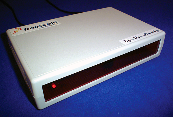 |
| FIGURE 1. This is the Green Standby device in action. Just plug the appliance in the back and connect it to the grid to start saving energy! |
Most of today’s home appliances have no genuine off switch. They are instead equipped with standby circuitry over which users have no direct control. The main power switch controls only the low voltage circuitry and even when the machine appears to be turned off, it is still consuming a few watts of energy without any purpose.
Although solutions do really exist like the switchable mains outlet strip, they have a distinct disadvantage in home entertainment applications: Convenience vanishes if you can no longer switch the device on or off simply by zapping it with the remote control handset. Solutions of this kind have the key advantage that hardly any power is ever wasted on standby current. The downside is that you can no longer wake up the appliance with its remote control. With these semi-intelligent standby switches, you need to press an onboard button to rouse them again, wiping out half the attraction.
The proposed device (see Figure 1) reacts to virtually any key press of almost every infrared remote control on the market. It enables you to upgrade an existing appliance with poor standby characteristics, reducing standby current very significantly. It doesn’t need installation or any configuration.
The interface to the outside world comprises a 120 VAC mains input and output together with an infrared sensor and a power supply. When a button is pressed on the infrared handset and is registered by the IR sensor, the signal detector delivers a trigger pulse to the circuit’s microcontroller. This operates the relay and the 120 VAC outlet is powered. Additionally, current flow is monitored for a number of seconds. If the microcontroller recognizes normal operation, the relay remains activated. If the current drops below a preset threshold level, the relay is deactivated after a few seconds and the mains outlet is powered down. See Figure 2 for a detailed block diagram.
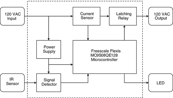 |
| FIGURE 2. High level block diagram of the Green Standby. |
Good for the Environment
Standby mode of operation refers to the lowest power consumption mode which cannot be switched off by the user and that may persist for an indefinite time when an appliance is connected to the main electricity supply and used in accordance with the manufacturer’s instructions.
Standby power is a relatively new phenomenon. An ever-growing number of consumer goods and appliances are now designed in a way that they draw power 24 hours a day, seven days a week, every week of the year.
Standby is often necessary to power certain core functions or to sense communication for those products that are waiting to provide full services. This power is consumed not while the appliance is being fully utilized, but while it awaits instruction. However, in many cases, standby power serves no useful function or operates at excessive levels.
Some studies estimate that the amount of energy wasted by running dormant devices left plugged in on standby power could light up, heat, and cool the homes of two-thirds of the planet. In the latest big study to track household energy use, the Australian government last year found that households squander 10 percent of their electrical bill on electronics that invisibly suck power.
As an example, other studies appraise that the annual collective standby power draw from households in the USA is around 8 Gigawatts — equivalent to the electricity production of eight large power plants. Globally, standby power consumption is estimated to be responsible for about 1% of the world’s carbon dioxide emissions.
Think about it. We could reduce 1% of the amount of carbon dioxide being spewed into the environment just by switching appliances off when not in use and all save some money on each power bill in the process!
How It Works
The installation procedure is really simple. There are no switches or complicated setup procedures to follow. As an example of use for a TV, simply connect the TV plug into the ‘Green Standby’ socket and finally connect the Green Standby to the power grid. A truly plug and play device!
As soon as the Green Standby is plugged into the mains, it flashes the red LED to show that the initialization process has finished successfully and enters in a much reduced power mode, waiting for a key press from the wireless infrared remote controller. Then, as soon as a key press is sensed, it wakes up and switches the TV on so you can choose your favorite channel to watch. Any subsequent key press from the wireless remote controller does not affect the Green Standby.
When the standby device is on, it is continually monitoring every half a second if the TV has been switched off by the user. If this is the case, it waits for five seconds to definitively switch the TV set off and enters into sleep mode, waiting for a new key press. See Figure 3 for a functional flowchart description.
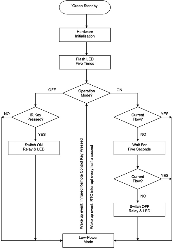 |
| FIGURE 3. Here is the flowchart of the application. Most of the time, the Green Standby is in a deep sleep mode, helping to consume only around 50 mW when idle. |
Circuit Description
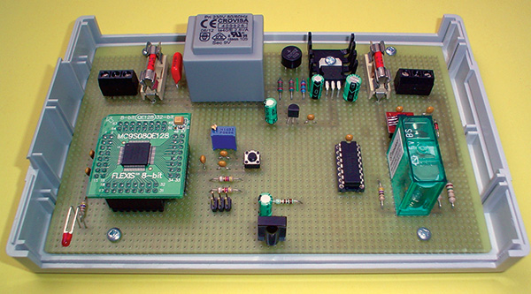
The hardware design (Figure 4) is built around the Freescale Flexis eight-bit MC9S08QE128 microcontroller. It has an impressive low power operation mode as required by this application. The use of the low power mode in the microcontroller allows a significant reduction in the overall power consumption.
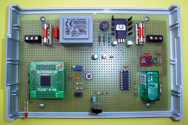 |
| FIGURE 4. Close-up view of the Green Standby’s internal circuitry. The hardware is so simple because the number of active components has been reduced in order to lower the total system power consumption. |
All the hardware design is oriented to low power consumption from the beginning. As a rule of thumb, the best way to reduce the overall power consumption is to minimize the number of active and passive components, as well as to choose low power components. Figure 5 shows the hardware schematic.
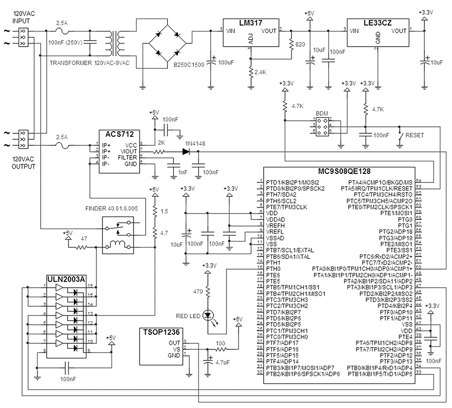 |
| FIGURE 5. Here is the board’s schematic based on the Freescale Flexis eight-bit MC9S08QE128 microcontroller. |
The type of power supply is an important issue for energy conservation. So, instead of using a conventional fixed voltage regulator such as the LM7805 with a residual current of up to 6 mA, I opted for a standard adjustable voltage regulator such as the LM317. It delivers a stable output voltage with a quiescent current of just around 1.5 mA. To power the microcontroller at 3.3V, I selected the LE33CZ fixed low dropout voltage regulator from ST Microelectronics with a quiescent current of just 1.5 mA. For further energy-saving considerations in the power supply, you can use a low overhead regulator, but take into account that they are more expensive and difficult to find. With respect to the transformer, although they have improved continuously over the past years, they still have some losses. So, using a good quality transformer makes good sense.
For the relay used, I decided to use a single-coil latching relay instead of a classic relay. This relay can pose a design challenge because coil current must flow in both directions through a single coil. Current flowing from a positive pin to negative pin causes the relay to latch in its reset position. On the contrary, current flowing from a negative pin to positive pin latches the relay in its set position. The relay maintains its position even when the coil current is removed, so power is saved by removing coil current after the relay latches.
The main advantage of a latching relay over a classic relay is that as soon as the relay has switched, it remains in that position without consuming energy. So, no current consumption means less heat production, hence smaller heatsinks. Best of all is a dramatic decrease in power consumption. In addition, the relay driver is built around a standard ULN2003A Darlington driver instead of using a half-bridge circuit. This simplifies the hardware.
There are several options available for the current sensing method used. The load current can be sensed by either using a current transformer or by passing the current through a very small resistor and then measuring the voltage across this resistor. As an advantage, a current transformer offers isolation through the transfer of current from the primary to the secondary winding. It can also handle higher currents than a resistor and consumes less power.
However, current transformers are more expensive and less accurate than resistors. Another disadvantage of current transformers is that the core can saturate in large current applications making the device highly non-linear, thus causing measurement errors. On the other hand, I discarded the use of a resistor as a current sensor because it might cause other nearby components to overheat.
In addition, both solutions need additional active components for signal conditioning and amplification. So, I decided to use an integrated Hall-effect chip such as the ACS712 from Allegro Microsystems. Its output can be directly connected to the analog to digital converter of the microcontroller, reducing the number of components and hence power consumption.
The IR sensor and signal detector are combined in the monolithic TSOP1236 IR receiver module from Vishay Semiconductors working at 36 kHz which is the standard frequency used in most of the wireless infrared remote controllers available on the market.
Additionally, there is an activity red LED to show when the device is switched on.
Finally, there is a standard Freescale six-pin BDM connector for in-system programming in order to update the Flash memory in case further updates or enhancements are planned in the future.
Summarizing, the entire electronics (Figure 6) draw less than 50 mW. Compared with the energy wasted by conventional standby equipment (around 3W), this is truly negligible!
 |
| FIGURE 6. Although initially the hardware was designed to work at 230 VAC (European standard), it can be easily modified for operation at 120 VAC (US standard) by changing the transformer. |
Firmware Design
The microcontroller tools used to develop the Green Standby firmware were Freescale CodeWarrior version 6.2 and the P&E Multilink interface for debugging and programming the Flash memory. To download CodeWarrior Special Edition and test a trial version of the C-compiler, visit the Freescale website at www.freescale.com
All the software has been developed in C in a modular way so that maintenance and improvements are fairly simple to do. A module hierarchy of the design is shown in Figure 7.
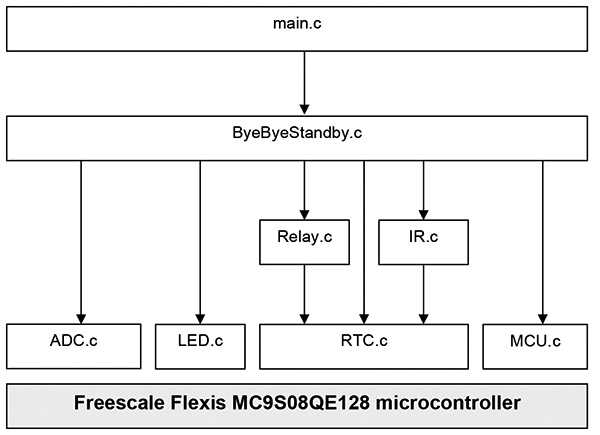 |
| FIGURE 7. The module hierarchy in the software design is fairly simple. There are different layers of complexity. Each microcontroller peripheral has its own driver in a separate source file to improve maintainability. |
Table 1 gives a brief description of each module and its hierarchy in the design. For more detailed information, you can take a look at the source code provided in the downloads section below at www.nutsvolts.com.
TABLE 1
| Module |
Description |
Functions |
| Main.c |
This is the main program |
main (…) |
| ByeByeStandby.c |
This file contains the set of functions necessary to build the ‘Bye Bye Standby’ application |
ByeByeStandby_Init (…)
ByeByeStandby_Welcome (…)
ByeByeStandby_On (…)
ByeByeStandby_Off (…)
ByeByeStandby_Mode (…)
ByeByeStandby_InfraredRemote
ControlKeyPressed (…) ByeByeStandby_PeripheralInStandbyMode (…)
ByeByeStandby_Sleep (…) |
| ADC.c |
This file allows to manage the ADC converter driver |
ADC_Init (…)
ADC_Start (…)
ADC_Read (…)
ADC_Stop (…) |
| LED.c |
This file allows to manage the LED driver |
LED_Init (…)
LED_On (…)
LED_Off (…) |
| IR.c |
This file allows to manage the IR receiver driver |
IR_Init (…)
IR_Enable (…)
IR_Disable (…)
IR_Mode (…)
IR_ISR (…) |
| Relay.c |
This file allows to manage the latching relay driver |
Relay_Init (…)
Relay_Open (…)
Relay_Closed (…)
Relay_Mode (…) |
| RTC.c |
This file allows to manage the Real Time Clock driver |
RTC_Init (…)
RTC_Start (…)
RTC_Stop (…)
TC_Delay (…)
RTC_Enable (…)
RTC_Disable (…)
RTC_ISR (…) |
| MCU.c |
This files allows to initialize the microcontroller resources |
MCU_Init (…) |
Green Electronics
Green electronics is becoming an increasingly popular design trend. The importance of hardware that is environmentally friendly is gaining attention worldwide.
You have learned how to use the low power modes available on modern microcontrollers’ architecture so that with the help of a very basic firmware algorithm, your hardware can be considered as green electronics. In addition, you have also learned how to use a single coil latching relay instead of a classic relay in order to reduce the total power consumption of the system.
There is definitely room for improvement. For instance, you can modify the hardware to handle more than one appliance at the same time using just one wireless remote controller, making the Green Standby a true multi-appliance device controller. NV
About the Author
Carlos Cossio earned a B.S. in Physics (majoring in electronics) at the University of Cantabria in Spain. He is a senior smart card engineer with more than 15 years of experience designing trusted security platforms. In his spare time, Carlos enjoys repairing and bringing old electronics equipment to life. The design described in this article was chosen as a top five finalist in the European first Green Freescale Technology Forum Design Challenge 2008.
PARTS LIST
| PART |
QTY |
DESCRIPTION |
| MCS9S08QE128 |
1 |
Freescale Semiconductor Flexis eight-bit microcontroller |
| Transformer 120 VAC |
1 |
120 VAC – 9 VAC voltage transformer to 9 VAC |
| Finder 40.61.6.005 |
1 |
Finder single-coil latching relay |
| ACS712-05 |
1 |
Allegro Systems Hall-effect current sensor (5A) |
| TSOP1236 |
1 |
Vishay Semiconductors IR receiver module for remote control |
| ULN2003A |
1 |
ST Microelectronics relay Darlington buffer |
| LM317T |
1 |
National Semiconductor three-terminal adjustable voltage regulator |
| LE33CZ |
1 |
ST Microelectronics low-dropout 3.3 voltage regulator |
| B250C1500 |
1 |
Full bridge rectifier |
| 2.4K Ω |
1 |
1% precision resistor 1/4W |
| 820 Ω |
1 |
5% resistor 1/4W |
| 4.7K Ω |
2 |
5% resistor 1/4W |
| 2K Ω |
1 |
1% resistor 1/4W |
| 47 Ω |
1 |
5% resistor 1/4W |
| 4.7 Ω |
1 |
5% resistor 1/4W |
| 1.5 Ω |
1 |
5% resistor 1/4W |
| 100 Ω |
1 |
5% resistor 1/4W |
| 470 Ω |
1 |
5% resistor 1/4W |
| 100 µF |
1 |
Aluminum electrolytic capacitor 16V |
| 10 µF |
3 |
Aluminum electrolytic capacitor 35V |
| 4.7 µF |
1 |
Aluminum electrolytic capacitor 63V |
| 100 nF |
8 |
Ceramic film capacitor |
| 100K250 |
1 |
MKT capacitor |
| 1 nF |
1 |
Ceramic film capacitor |
| LED |
1 |
Red LED |
| 1N4148 |
1 |
Fast switching diode |
| Fuse 2.5A |
2 |
Fuse |
| Fuse holder |
2 |
Fuse holder |
| Switch |
1 |
Micro pushbutton |
| Six-pin header |
1 |
BDM six-pin connector |
| Three-pin AC power PCB connector |
2 |
AC power connector |
Resources
MC9S08QE128 Datasheet
Freescale Semiconductors, 2007
MC9S08QE128 Reference Manual
Freescale Semiconductors, 2007
DEMOQE128 User Manual
PE Micro, 2007
USB HCS08/HCS12 Multilink Technical Summary
PE Micro, 2007
ACS712 Fully Integrated Hall-Effect Based Linear Current Sensor Datasheet
Allegro MicroSystems, 2007
LExxC Very Low Drop Voltage Regulators With Inhibit Datasheet
ST Microelectronics, 2007
LM117/LM317 Three-Terminal Adjustable Regulator Datasheet
National Semiconductor, 2007
TSOP12xx IR Receiver Modules For Remote Control Systems Datasheet
Vishay Semiconductors, 2007.
ULN2003A 5-V TTL Seven Darlington Arrays Datasheet ST Microelectronics, 1991
40 Series Miniature PCB Relays 8, 10, 16A, Finder, 2008
Downloads
Green Standby Source Codes