In Otherwise Low Voltage Devices
Everybody loves Nixie tubes. The pleasant, archaic orange glow of their digits is popular and comforting in clocks and other devices (like counters) with numeric outputs. Nixies were introduced when vacuum tube hardware automatically provided the high voltage they require. In the modern almost-all-semiconductor era, however, circuitry typically runs on five volts or less, so finding the +170V or so for Nixie’s anodes can be a bit of a challenge. Up-converting low current switching supplies are popular. However, in contrast, here are three transformer based ways to obtain that high voltage in line-powered semiconductor based devices.
About Nixies
Nixies, of course, are essentially neon lights. A Nixie contains a single anode to which a high voltage is applied and several cathodes that are usually in the shapes of the 10 digits, though other symbols are sometimes implemented.
When a cathode is grounded, electrons travel from it to the anode and the gas around that cathode glows, illuminating the symbol. The current required to illuminate a cathode is minimal: one mA or so. Burroughs introduced Nixies in 1955, and they were used for several decades in test equipment and calculators. Figure 1 shows a Burroughs B5991 with a digit lit up.
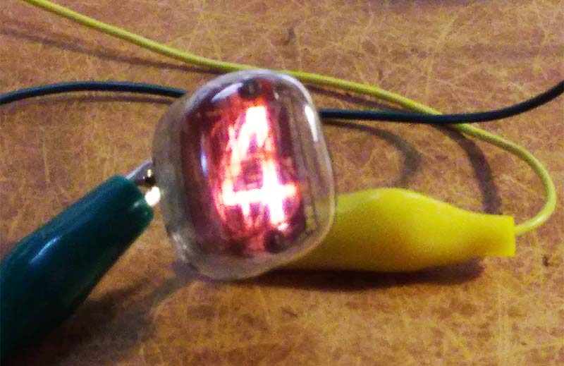
FIGURE 1. A Nixie tube, of course. Enjoy the glow.
Up-Converters
Various on-line outlets offer small boost supplies that accept 9-12 VDC and produce up to +300V. The tiny current that Nixies draw makes these units possible. They are already assembled and therefore convenient, but less fun than building them ourselves. Many circuits on-line and in print implement similar boost supplies. One such unit was described in these pages back in April 2008; it used an MC34063 switching regulator. Figure 2 shows one of the commercial supplies and a home-brew unit based on a circuit found on-line, that uses the familiar NE555 timer.
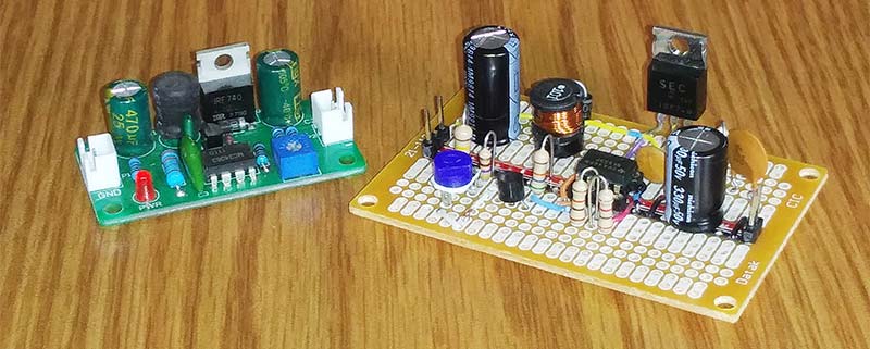
FIGURE 2. Two low current boost supplies. On the left, a commercially available assembled unit. On the right, a circuit similar to one on-line using an NE555.
Transformer Based Supplies
Other power supply possibilities are more historically consistent with the Nixies themselves. Tube-based devices generally require a power transformer that provides both a low voltage for the tube’s filaments and a high voltage for their plates. A typical small transformer might yield both 6.3V and 125V. The +5V that, say, a clock’s circuitry requires can be derived from the low voltage winding through a rectifier and (usually) a regulator, and the +170V or so for the Nixies can be developed from the high voltage winding. The low current required at the high voltage makes it possible to obtain it from that secondary.
Such transformers are available at hamfests and from various on-line vendors. Figure 3 shows a Nixie clock that uses a supply based on such a transformer, and Figure 4(a) shows the transformer’s circuit. (Figure 3 is not upside down. The Nixies in this clock are NL-874s and NL-875s; it’s their elements that are inverted.)
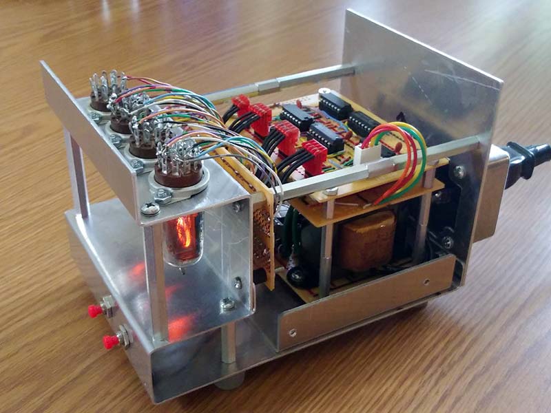
FIGURE 3. A Nixie clock that develops its high voltage from a small transformer.
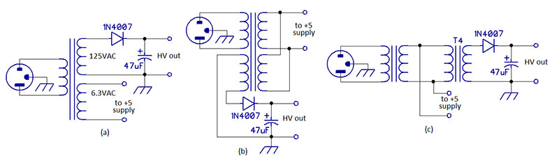
FIGURE 4. Three transformer based circuits to develop the high voltage that Nixies require.
Similarly, many small transformers available today have two primary windings. When these primaries are connected in parallel, the transformer’s input is intended to be 117 VAC as in the US. In series (correctly phased), they can be used with 230 VAC input as in Europe.
Nothing is special, however, about those two “primary” windings. One of them can be used as a secondary from which the requisite high voltage can be derived, as in Figure 4(b). (These transformers often have two identical secondaries as well. Connect them in series or parallel as necessary to obtain the low voltage.)
Finally, one can use two low voltage transformers back-to-back. Consider a 9V transformer, from which the voltage to power a clock’s circuitry is derived. That transformer’s secondary is also connected to the secondary of another similar transformer.
The voltage available at that transformer’s primary will be enough — when rectified — to light up the device’s Nixies. Figure 4(c) illustrates this arrangement. If a slightly higher output voltage is required, the second transformer should have a lower secondary rating.
Regulation
It’s convenient to have precise control over the high voltage generated by these circuits. The tool of choice here is the LR8N3 three-terminal high-voltage regulator. It comes in a TO-92 package, accepts inputs as high as 450V, and yields regulated output up to 18V less than its input. Its maximum current is 20 mA — ample to power four or six Nixies.
Figure 5 shows a circuit that provides a regulated output voltage of about +180V using standard value parts. (The astute reader will notice that this is a fixed output/low current version of the regulator in the adjustable high voltage supply that I described here back in Issue-5 2019.)
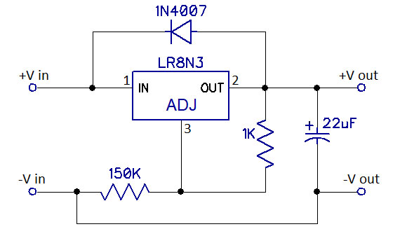
FIGURE 5. LR8N3 low current regulator that yields about +180V.
However the high voltage is developed, don’t forget the current-limiting resistor in the anode circuit of each Nixie.
The Usual Caution
Though the currents at high voltages here are small, the voltages can still be dangerous, so exercise the necessary caution. And enjoy that comforting orange glow. NV