With a Useable Keyboard, Courtesy of the Arduino Nano Every
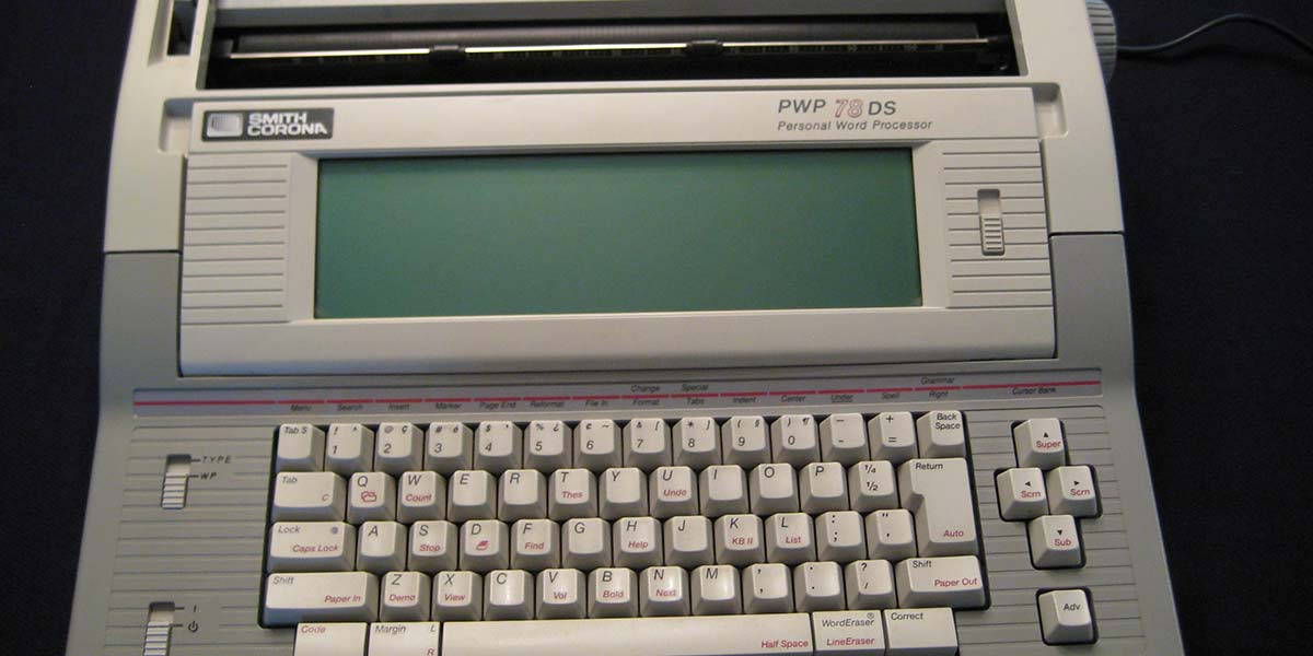
I bought a Smith-Corona PWP 78DS typewriter from Good Will for under $20. The daisy wheel print quality was perfect, and it included a self-contained word processor (PWP = Personal Word Processor). However, there was no way to use it as a printer. I decided to emulate the membrane keyboard with an Arduino Nano Every, so that either an added serial port or the existing keyboard could input text. Along the way, I re-discovered RS-232 serial cable transmission. (In this age of wireless communication through the Internet of Things, the serial cable has been all but forgotten.) I also solved the mystery of the membrane keyboard and discovered some tips on creating with the Nano Every, which is surprisingly different from the original Arduino.
Many experimenters have converted typewriters to printers by mounting a bank of solenoids on top of the keyboard. This prints correctly, but it prevents typing on the keyboard again until the solenoid bank is removed.
One hobbyist solved this problem by mounting a bank of car door lock actuators below the keyboard, using actuators tied to keys with strings. Due to the bulk on the bottom, it wouldn’t fit on a tabletop. A special wood cabinet was built for it. I decided on a method which did not use solenoids or actuators.
The first step was to use an oscilloscope to examine the typewriter chips, looking for traces that showed a serial signal or ASCII parallel signals. I couldn’t find any. In the process, I occasionally scoped a clock pin which halted the microprocessor. I figured I would damage the chips this way, so I stopped scoping.
In the absence of existing serial or parallel signals, the best way to input text to the typewriter was through its keyboard. I used an Arduino Nano Every to simulate the membrane keyboard, so that either an added RS-232 port or the existing keyboard could input text. The Nano Every was chosen because it has a small form factor and a maximum power input of +21V, while the typewriter supplies +20V for its print head.
The Smith-Corona keyboard does not output either serial or ASCII parallel codes. Instead, it forms an 8 x 8 matrix which shorts two wires together when a key is pressed. (There are 61 keys on the PWP keyboard, allowing for three unused combinations in the 64-slot matrix. I employed one of the three [0x02] to indicate a non-printing character, such as BELL.)
The Mystery of the Membrane Keyboard
The keyboard membrane cable has pins 1 to 18 (see Figure 1).
KEYBOARD CONNECTIONS
| KBD |
LOW |
HIGH |
SHIFT |
CODE |
NANO |
| 18 |
L7 |
|
|
F |
A7 |
| 17 |
L6 |
|
|
E |
A6 |
| 16 |
L5 |
|
|
D |
A5 |
| 15 |
L4 |
|
|
C |
A4 |
| 14 |
L3 |
|
|
B |
A3 |
| 13 |
L2 |
|
|
A |
A2 |
| 12 |
L1 |
|
|
9 |
A1 |
| 11 |
|
Caps Lock Light |
|
|
| 10 |
|
Caps Lock Light |
|
|
| 9 |
|
H7 |
F |
|
D9 |
| 8 |
|
H6 |
E |
|
D8 |
| 7 |
|
H5 |
D |
|
D7 |
| 6 |
|
H4 |
C |
|
D6 |
| 5 |
|
H3 |
B |
|
D5 |
| 4 |
|
H2 |
A |
|
D4 |
| 3 |
L0 |
|
|
8 |
A0 |
| 2 |
|
H1 |
9 |
|
D3 |
| 1 |
|
H0 |
8 |
|
D2 |
FIGURE 1. Primarily, this chart shows the relationships between the keyboard cable, the low lines, the high lines, and the Arduino Nano Every pins they connect to. Given the state of Code and Shift, the secondary use is to generate the hexadecimal numbers (0 through F) which are used to populate the Flex Array. See text under “The Mystery of the Membrane Keyboard.”
Pins 10 and 11 supply power to the Caps Lock LED. With no key pressed, pin 3 and pins 12 through 18 are low (let’s call these the eight low lines), and pins 1, 2, and 4 through 9 are high (we’ll call these the eight high lines.) When any key is pressed, a high line is shorted to low.
Next, the typewriter puts a high pulse 0.5 msec wide every 5 msec on every low line, but pulses are staggered so the typewriter can tell which low line is connected to the pressed key. The high line follows whatever level the connected low line happens to be in, until the key is released when the high line returns to high.
Here’s where things get really tricky. If the Shift key is held down while a letter is struck, two high lines are involved: one for the Shift key and one for the letter. Depending on the letter, it’s possible for both high lines to be the same line, so this one wire pulses low at two different times. Even stranger, this common output line is shorted to two inputs that could be in different states (one high, one low).
Can you predict what the output of such a circuit would be? Voltage half-way between high and low? Oscillation? Blown fuse? Undefined?
The answer is low. I found by experimentation that ground takes precedence. This is the opposite of what would be expected from a wired-OR circuit. In a wired-OR, any high in gets a high out. In the membrane keyboard, any low in gets a low out.
To make things even more complicated, there’s a second type of Shift key called “Code.” If the Code key is held down and the letter b is struck, the following text will be Bolded. This Code key is used to start and stop Bold, Center, Sub Script, Super Script, and Underline. If Code and Shift are both asserted, the following 10 special characters can be typed: ^ ç é ` ¿ ~ [ ] §¶ (see Figure 2). Examples: café (coffee), côte (coast), frère (brother), garçon (boy), ¿El niño? (The boy?).
MEMBRANE KEYBOARD LINES FOR EACH KEY
| |
|
|
|
|
LINE |
|
|
LINE |
|
|
|
| |
SYMBOL |
|
SHIFT |
CODE |
HIGH |
LOW |
SYMBOL |
SHIFT |
HIGH |
LOW |
|
|
|
|
| |
1 |
|
! |
^ |
8 |
15 |
l |
L |
8 |
18 |
|
|
|
|
| |
2 |
|
@ |
ç |
7 |
15 |
m |
M |
5 |
18 |
|
|
|
|
| |
3 |
|
# |
é |
6 |
15 |
n |
N |
2 |
12 |
|
|
|
|
| |
4 |
|
$ |
` |
5 |
15 |
o |
O |
7 |
17 |
|
|
|
|
| |
5 |
|
% |
¿ |
4 |
15 |
p |
P |
6 |
17 |
|
|
|
|
| |
6 |
|
¢ |
~ |
2 |
15 |
q |
Q |
8 |
14 |
|
|
|
|
| |
7 |
|
& |
[ |
9 |
16 |
r |
R |
5 |
14 |
|
|
|
|
| |
8 |
|
* |
] |
8 |
16 |
s |
S |
7 |
13 |
|
|
|
|
| |
9 |
|
( |
§ |
7 |
16 |
t |
T |
4 |
14 |
|
|
|
|
| |
0 |
|
) |
¶ |
6 |
16 |
u |
U |
9 |
17 |
|
|
|
|
| |
a |
|
A |
|
8 |
13 |
v |
V |
5 |
12 |
|
|
|
|
| |
b |
|
B |
|
4 |
12 |
w |
W |
7 |
14 |
|
|
|
|
| |
c |
|
C |
|
6 |
12 |
x |
C |
7 |
12 |
|
|
|
|
| |
d |
|
D |
|
6 |
13 |
y |
Y |
2 |
14 |
|
|
|
|
| |
e |
|
E |
|
6 |
14 |
z |
Z |
8 |
12 |
|
|
|
|
| |
f |
|
F |
|
5 |
13 |
- |
_ |
5 |
16 |
|
|
|
|
| |
g |
|
G |
|
4 |
13 |
= |
+ |
4 |
16 |
|
|
|
|
| |
h |
|
H |
|
2 |
13 |
½ |
¼ |
5 |
17 |
|
|
|
|
| |
i |
|
I |
|
8 |
17 |
; |
: |
7 |
18 |
|
|
|
|
| |
j |
|
J |
|
2 |
17 |
‘ |
“ |
6 |
18 |
|
|
|
|
| |
k |
|
K |
|
9 |
18 |
, |
, |
4 |
18 |
|
|
|
|
| |
. |
|
. |
|
2 |
18 |
? |
/ |
8 |
3 |
|
|
|
|
| |
Return |
|
|
|
4 |
17 |
Space |
|
5 |
3 |
|
|
|
|
| |
Back Space |
|
|
|
2 |
16 |
Up - Super Script |
|
1 |
18 |
|
|
|
|
| |
Down - Sub Script |
|
|
|
1 |
3 |
Right |
|
1 |
16 |
|
|
|
|
| |
Left |
|
|
|
1 |
17 |
Adv |
|
1 |
12 |
|
|
|
|
| |
Margin |
|
|
|
6 |
3 |
Code |
|
7 |
3 |
|
|
|
|
| |
Shift - Right |
|
|
|
9 |
3 |
Shift - Left |
|
9 |
12 |
|
|
|
|
| |
Caps Lock |
|
|
|
9 |
13 |
Tab |
|
9 |
14 |
|
|
|
|
| |
Tab S |
|
|
|
9 |
15 |
Word Eraser |
|
4 |
3 |
|
|
|
|
| |
Correct |
|
|
|
2 |
3 |
|
|
|
|
|
|
|
|
FIGURE 2. A chart specifying what lines are shorted for each key press. To print the foreign language characters listed under CODE, both Shift and Code must be asserted.
ASCII characters missing from the print wheel — including \, |, {, }, <, and > — are all replaced by @ in the Flex Array; ¼, ½, and ¢ are printable by embedding Alt-028, Alt-029, or Alt-030 into the document to be printed (see Figure 3).
CONTENTS OF FLEX ARRAY
| 0 |
NULL |
0x02 |
32 |
Space |
0x30 |
64 |
@ |
0xD4 |
96 |
` |
0xBC |
| 1 |
SOH |
0x02 |
33 |
! |
0xE4 |
65 |
A |
0xE2 |
97 |
a |
0x62 |
| 2 |
Code |
0x50 |
34 |
“ |
0xC7 |
66 |
B |
0xA1 |
98 |
b |
0x21 |
| 3 |
Shift Left |
0x71 |
35 |
# |
0xC4 |
67 |
C |
0xC1 |
99 |
c |
0x41 |
| 4 |
Shift Right |
0x70 |
36 |
$ |
0xB4 |
68 |
D |
0xC2 |
100 |
d |
0x42 |
| 5 |
Caps Lock |
0x72 |
37 |
% |
0xA4 |
69 |
E |
0xC3 |
101 |
e |
0x43 |
| 6 |
ACK |
0x02 |
38 |
& |
0xF5 |
70 |
F |
0xB2 |
102 |
f |
0x32 |
| 7 |
BELL |
0x02 |
39 |
‘ |
0x47 |
71 |
G |
0xA2 |
103 |
g |
0x22 |
| 8 |
Back Space |
0x15 |
40 |
( |
0xD5 |
72 |
H |
0x92 |
104 |
h |
0x12 |
| 9 |
TAB |
0x73 |
41 |
) |
0xC5 |
73 |
I |
0xE6 |
105 |
i |
0x66 |
| 10 |
Line Feed |
0x02 |
42 |
* |
0xE5 |
74 |
J |
0x96 |
106 |
j |
0x16 |
| 11 |
Vert Tab |
0x02 |
43 |
+ |
0xA5 |
75 |
K |
0xF7 |
107 |
k |
0x77 |
| 12 |
Form Feed |
0x78 |
44 |
, |
0x27 |
76 |
L |
0xE7 |
108 |
l |
0x67 |
| 13 |
Return |
0x26 |
45 |
- |
0x35 |
77 |
M |
0xB7 |
109 |
m |
0x37 |
| 14 |
Bold |
0x29 |
46 |
. |
0x17 |
78 |
N |
0x91 |
110 |
n |
0x11 |
| 15 |
Center |
0x4D |
47 |
/ |
0x60 |
79 |
O |
0xD6 |
111 |
o |
0x56 |
| 16 |
Ctrl-P |
0x02 |
48 |
0 |
0x45 |
80 |
P |
0xC6 |
112 |
p |
0x46 |
| 17 |
X-On |
0x02 |
49 |
1 |
0x64 |
81 |
Q |
0xE3 |
113 |
q |
0x63 |
| 18 |
Underline |
0x3D |
50 |
2 |
0x54 |
82 |
R |
0xB3 |
114 |
r |
0x33 |
| 19 |
X-Off |
0x02 |
51 |
3 |
0x44 |
83 |
S |
0xD2 |
115 |
s |
0x52 |
| 20 |
Sub Script |
0x08 |
52 |
4 |
0x34 |
84 |
T |
0xA3 |
116 |
t |
0x23 |
| 21 |
¶ |
0xCD |
53 |
5 |
0x24 |
85 |
U |
0xF6 |
117 |
u |
0x76 |
| 22 |
§ |
0xDD |
54 |
6 |
0x14 |
86 |
V |
0xB1 |
118 |
v |
0x31 |
| 23 |
ç |
0xDC |
55 |
7 |
0x75 |
87 |
W |
0xD3 |
119 |
w |
0x53 |
| 24 |
é |
0xCC |
56 |
8 |
0x65 |
88 |
X |
0xD1 |
120 |
x |
0x51 |
| 25 |
¿ |
0xAC |
57 |
9 |
0x55 |
89 |
Y |
0x93 |
121 |
y |
0x13 |
| 26 |
Ctrl-Z |
0x02 |
58 |
: |
0xD7 |
90 |
Z |
0xE1 |
122 |
z |
0x61 |
| 27 |
Escape |
0x02 |
59 |
; |
0x57 |
91 |
[ |
0xFD |
123 |
{ |
0xD4 |
| 28 |
¼ |
0xB6 |
60 |
< |
0xD4 |
92 |
\ |
0xD4 |
124 |
| |
0xD4 |
| 29 |
½ |
0x36 |
61 |
= |
0x25 |
93 |
] |
0xED |
125 |
} |
0xD4 |
| 30 |
¢ |
0x94 |
62 |
> |
0xD4 |
94 |
^ |
0xEC |
126 |
~ |
0x9C |
| 31 |
SuperScript |
0x0F |
63 |
? |
0xE0 |
95 |
_ |
0xB5 |
127 |
Del |
0x10 |
FIGURE 3. Contents of the Flex Array. Each value — called a FlexVal — begins with “0x” which just means the value is a hexadecimal number. 0x can be ignored. To understand substitutions in the first column of the array, see the sidebar called “How the Contents of the Flex Array Are Derived.”
In fact, any character can be printed that way. Type 028 on the numeric keypad of the Windows computer with Num Lock on and Alt held down for all three digits.
HOW THE CONTENTS OF THE FLEX ARRAY ARE DERIVED
Let’s take the capital U as an example. A glance at Figure 2 will show that the U key shorts pins 9 and 17 together. Figure 1 shows that pin 9 corresponds to a high line of H7, but since this is a capital U, Shift is also present, so the high line is represented by F.
Bit 7 = Shift bit
Bits 6, 5, and 4 = Select a high line H0 through H7
Bit 3 = Code bit
Bits 2, 1, and 0 = Select a low line L0 through L7
Pin 17 is consistent with a low line of L6 and there is no Code bit. Therefore, dropping H and L, the FlexVal for U in the Flex Array should be 0xF6. Figure 3 shows this to be correct. The Flex Array is addressed by the ASCII code of the print character.
The first column of ASCII characters in Figure 3 are mostly unused, so they can be re-purposed to mean Bold, Center, Sub Script, Super Script, and Underline, as well as foreign language symbols. However, some ASCII values cannot be repurposed.
Recall that under DOS, Ctrl-P does not mean Print like it does under Windows. Under DOS, Ctrl-P-ESC inserts an Escape character. X-On, X-Off, Ctrl-P, and Ctrl-Z appear in the Flex Array; not to generate an Escape character, but to ensure that those functions are preserved.
Inventing with the Arduino Nano Every
The Nano Every requires an extra step before a sketch can be run. In the Arduino IDE (integrated development environment), click on Tools → Boards → Boards Manager. Search for megaAVR and install the ‘Arduino megaAVR Boards’ package. If it asks you to accept warnings or drivers as it installs, accept them.
After installation, select Tools → Boards → Arduino megaAVR boards → Arduino Nano Every. Connect the Nano Every to the computer. The system should load the correct device driver if needed. The orange LED on the Nano Every should flash, signifying that the Blink sketch is running. It comes pre-installed. (If you can’t imagine what I’m talking about, don’t worry about it.)
Each time a sketch is uploaded to the Nano Every, the following message appears: ‘Avrdude: jtagmkII_initialize(): Cannot locate “flash” and “boot” memories in description’ … this is not an error. It’s a well-known warning, and it can be safely ignored.
On the Arduino Uno, digital and analog pins are in different connector blocks. To make the 10th digital pin high, the command is digitalWrite(10, HIGH); but on the Nano Every, power pins, reset pins, and a reference pin are all mixed in with the digital and analog pins. The lowest usable digital pin, D2, is actually on pin 5, but it must be accessed using its D-number: digitalWrite(2, HIGH);.
To access the analog pins, skip the power and reference pins between pin D13 and A0. The next number after 13 is 14. The first analog pin, A0, is accessed using 14. The command is:
if (digitalRead(14) == HIGH) {
In summary, to access a digital pin D0 through D7, add 2 to the number (for D7, 7 + 2 = 9). To access an analog pin A0 through A7, add 14 to the number (for A7, 7 + 14 = 21). Pin D13 is connected to a built-in LED on the Nano Every board, but the oscilloscope shows that the LED is a significant load which lowers the voltage at the pin, whether it’s configured as an input or output. It’s probably best to choose another pin for I/O and let pin D13 control the LED.
First, Do No Harm
After figuring out how the membrane keyboard worked, the next step was to pass keyboard signals through my circuit without alteration (see Figure 4).
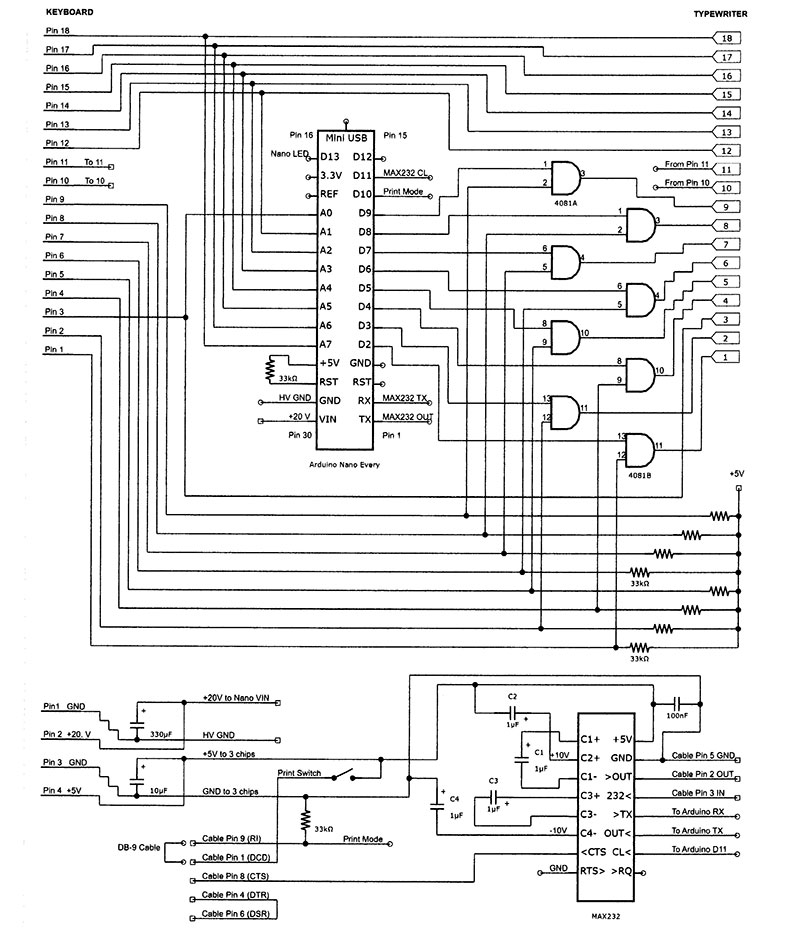
FIGURE 4. Schematic for the daisy wheel printer. Note that the Nano Every is drawn upside down, with pin 1 at the bottom of the Arduino. The serial cable shows five pins on the lower left and three pins on the lower right. The MAX232 pins are labeled with arrows to indicate input and output. Note the polarity of the four electrolytic capacitors connected to the MAX232.
The serial cable was not needed at this stage. I discovered I could make the circuit diagram a lot simpler if I drew the Nano Every upside-down, with pin 1 at the bottom of the Arduino. This eliminated many hard-to-follow lines that had been swirling around the Arduino drawing like a painting by Van Gogh.
At first, I soldered the Nano Every directly to my card (see Photo 1).
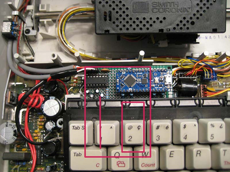
PHOTO 1. The original position of my card is outlined in red, with the Arduino completely hidden under the keyboard. The Nano Every was initially soldered to the card without a socket, so it could fit under the keyboard. The keyboard cable connector was originally where the vertical red line is, but the cable kept pulling out of it, so the connector was moved to a pigtail. Note the Print switch in the upper left.
Originally, the card was rotated 90 degrees as outlined in red. The Arduino was hidden below the keyboard, and the keyboard connector was soldered directly to the card where the single red line is.
In this position, the keyboard cable simply would not stay connected. The membrane cable was stiff enough that it kept pulling the upper half of the cable out of the connector. That’s why the card eventually needed two pigtails (see Photos 2 and 3).
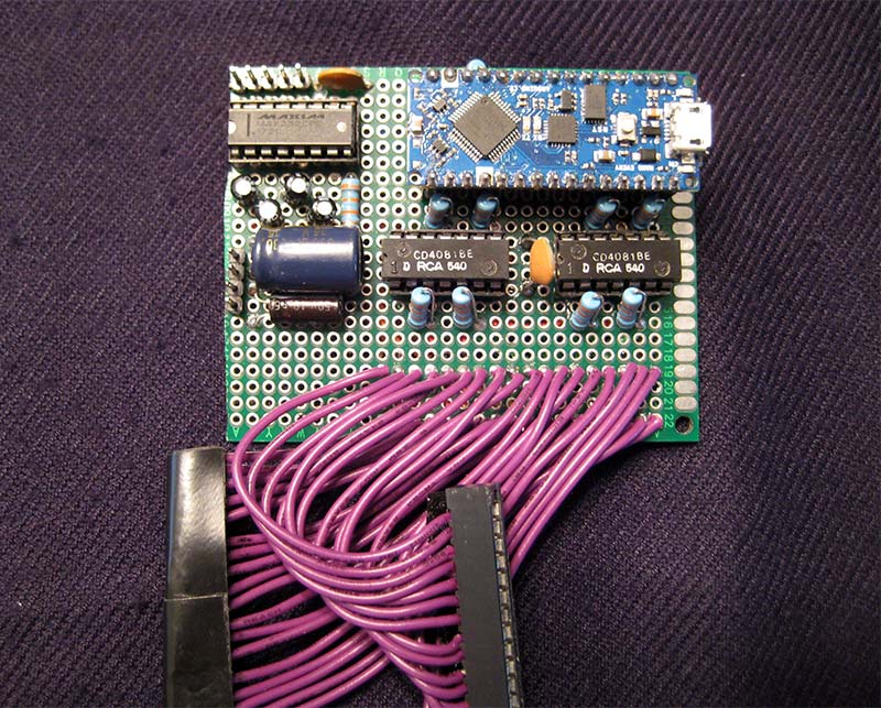
PHOTO 2. Top view of my card, showing the Arduino Nano Every, the MAX232, and two CMOS 4081 quad AND gates. (I tried replacing the CMOS chips with their TTL equivalent, so the output would be driven low as well as high, but the typewriter didn’t like it.) Also note the pins on the left edge that supply +5 and +20 volts, and the serial pins at the upper left which — when connected — lead to the serial cable. Large electrolytic capacitors are positioned where external power enters the card.

PHOTO 3. Bottom view of my card. The wire mat is color coded: high lines in green; low lines in orange; LED power in yellow; +5 volts power in red; ground in black; MAX232 signals in blue; pigtails in purple; +20 volts in white; and 20 volt return in gray. There is no connection between ground and the 20 volt return on this card. That’s done on the typewriter circuit board.
Disaster Strikes
After the circuit was able to print the letters that were typed on the keyboard, I connected the serial cable from the typewriter to a vintage IBM XT computer (circa 1983.) Although the XT was not powered on, circuits at both ends of the cable blew out.
The Arduino acquired a dead short between VIN (Voltage In) and GND (Ground), causing the typewriter to blow its fuse whenever my card was installed. The serial board in the XT was also destroyed, so I had to purchase another serial adapter from eBay.
I thought I might have to replace the Arduino again at some point, so I put its replacement in a socket. This meant the Arduino would no longer fit under the keyboard, so I rotated the board 90 degrees as shown in Photo 1.
What could blow out circuits at both ends of the serial cable? Grounding. The typewriter didn’t have a polarized power cord. I converted the existing cord into a polarized plug by cutting the top of one prong and spreading it as shown in Photo 4.
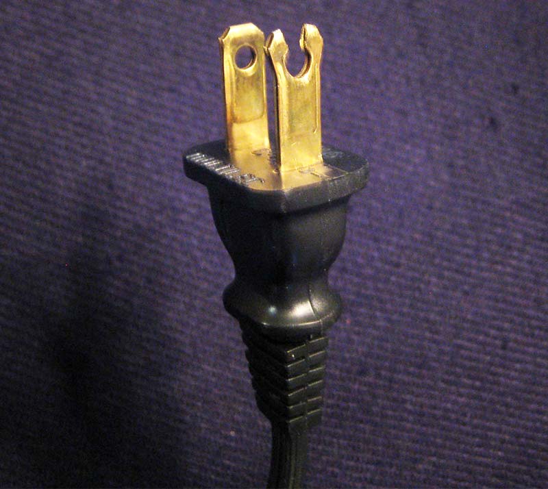
PHOTO 4. Creating a polarized plug from the existing typewriter power cord by splitting one prong and spreading it apart.
The trick is to spread the correct prong!
With both typewriter and XT power cords plugged into the wall, but with both powered off, I used a meter to measure the AC voltage between typewriter ground and serial cable ground. I then unplugged the typewriter power cord, reversed the prongs, and plugged it in again. Whichever position resulted in the lowest meter reading was made permanent by spreading the prong.
RS-232 Blues
Any Internet article on “Hardware Handshaking” will explain Request-to-Send (RTS) and Clear-to-Send (CTS) signals. When the computer wants to send serial data, it asserts RTS, and if the peripheral is ready to receive, it responds with CTS. The computer then sends the serial data and when it’s done, it drops RTS. The peripheral then responds by dropping CTS. This is how signals behaved when there were half-duplex modems (one direction at a time), but it’s not how they behave now.
Once asserted, RTS doesn’t drop. RTS stays asserted until the computer is powered off. RTS is useless to indicate when data will arrive or when CTS should be asserted. How can this be?
Long ago, a new signal called RTR (Ready to Receive) meant “Clear-to-Send to the Computer.” RTR was intended for use with full-duplex (bi-directional) modems, but here’s the kicker: RTR and RTS share the same pin! This is a clever way to change the meaning of a signal without changing its name! It’s still called RTS/CTS handshaking.
If you’re reluctant to embrace the new meaning of RTS, you’re not alone, given the websites that still champion the old tradition (RTS results in CTS.) Effectively, there are two Clear-to-Send signals: CTS means “OK to send to the Printer;” and RTS now means “OK to send to the Computer.” This change in meaning occurred 35 years ago, and I’m just now finding out about it.
Needless to say, my circuit doesn’t use RTS, but it still needs to know when CTS should be asserted. A manual switch could be used for this purpose, but detecting a cable connection would also work. In the end, I chose both. At the bottom of Figure 4, a signal called Print Mode is usually low, but it goes high when the serial cable is connected and the Print Switch is closed.
Enter the MAX232
The signal levels in the serial cable are at either +10 volts or -10 volts. A 20 volt difference yields excellent noise rejection. That’s why serial cables can be 15 meters long, compared to three or five meters for USB cables. However, that also means the serial signals must be converted from +10 and -10 volts to 0 and +5 volts. The MAX232 chip does that.
It not only converts the signals but inverts them. The IC runs on a +5 volt supply like most chips, but it generates its own +10 and -10 volts, thus eliminating the need for external power supplies.
Looking again at Figure 4, the polarity of the four electrolytic capacitors is sometimes mislabeled on the Internet. For example, look at capacitor C4. Its plus sign is connected to ground, which at first seems like a mistake. However, the other side of C4 is held at -10 volts, so ground is indeed more positive than -10 volts. More than one website got this wrong.
Here are some tips I’ve discovered about the MAX232:
- If CTS is asserted, its level in the serial cable is +10 volts.
- There must be a return data signal from the MAX232 to the IBM XT, even if it’s not used. The XT simply will not send TD (Transmit Data) without RD (Receive Data). (In Figure 4, RD is labeled OUT.)
- If four 1 µF capacitors will produce +10 and -10 volts, then four 2 µF caps will double the voltage, right? Wrong! Four 2 µF capacitors will output +7.5 and -7.5 volts. I actually tried this because I didn’t have the right parts.
- All unused inputs on the MAX232 must be grounded.
Typewriter Modifications
Take a look at Photo 5.
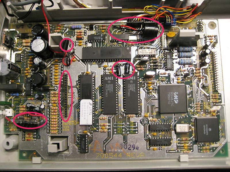
PHOTO 5. Changes made to the typewriter circuit board are circled in red. The one-time use fuse was replaced with a fuse holder. The keyboard cable connector was unsoldered from the board and replaced by Arduino pins. Directly above the Arduino pins is the power connector that supplies +5 and +20 volts to my card. The beeper was relocated two inches away, and two upright electrolytic capacitors were re-mounted flat to make room for my card.
There were two upright electrolytic capacitors that had to be laid on their sides, and the beeper had to be moved two inches to make room for m y card. Note the blown fuse was replaced with a fuse holder. I was never able to find a replacement part for the keyboard cable connector.
The biggest modification was to unsolder the membrane connector and replace it with Arduino pins. This allowed me to fasten the membrane connector to the pigtail (see Photo 6).
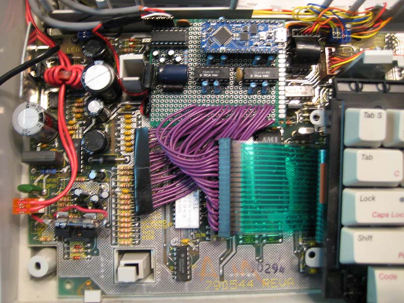
PHOTO 6. This shows clearly that my card is inserted between the keyboard and typewriter circuit board. The two electrolytic capacitors mentioned in Photo 5 are located underneath the lower right corner of the card (not visible).
The Software
As previously mentioned, if a key was pressed on the membrane keyboard, a high line and a low line were involved. The software routine to handle this was called twoLines(). If a Shift key was held down while a letter was struck, that was handled by fourLines(), except for the strange possibility where the two high lines were the same line.
I wrote threeLines() to handle that situation; twoLines() worked perfectly, but fourLines() left something to be desired when Capital letters were typed. I never could get threeLines() to work at all; it produced extra characters, missing characters, and wrong characters.
Caps Lock to the Rescue
Rather than holding down a Shift key, Caps Lock could be set using twoLines(), then the letter could be struck, again using only twoLines(). Finally, Caps Lock could be cleared by striking the Shift key, once more using only twoLines(). Caps Lock solved all the upper case problems and all the fourLines() problems.
The Code key still needs fourLines(), but normal computer printouts would not know about the Code key, so fourLines() would not normally be used. Furthermore, none of the Code key permutations involved threeLines(), so I could delete threeLines() altogether.
The 64-Byte Input Buffer
At this stage, the typewriter correctly printed the letters received over the serial cable. However, there’s no rest for the weary. No matter how long the text was, the Smith-Corona would only print the first 64 characters and then stop. This is because the Nano Every has a 64-byte serial input buffer.
There’s a way to extend the input buffer to 256 bytes, but that wouldn’t really help. At 9600 baud, the 64-byte input buffer would fill up in 66.6 msec. I tried receiving 48 characters and then dropping CTS to stop transmission, but never got it to work.
Then, I noticed that a full typewritten page had about 4,000 characters on it, so I created an array of 4096 bytes in the sketch. The snippet which receives serial data has to deal with the time before the data reception starts and the time after it’s done. It also has to count the number of letters it stores and decide if that number exceeds 4000. I took a chance that each byte would complete four questions in time to receive the next character, but it keeps up nicely. Here’s the entire snippet, colored the way it would appear in the Arduino IDE:
// This is part of the loop() routine. This snippet loads serial characters into the ring[4096] buffer.
// ‘head’ and ‘tail’ are initialized to 0 as integer. ‘active’, ‘after’, and ‘done’ are initialized to false
// as bool. PRINT is pin D10 (Print Mode in Figure 4).
else // Cable is detected and Print switch is on
{
digitalWrite(LED_BUILTIN, HIGH); // turn LED on to show Print Mode
digitalWrite(CTS, LOW); // Assert CTS once (MAX232 inverts signal)
while ((done == false) && (digitalRead(PRINT) == HIGH)) { // Low exits the while loop
if (Serial1.available() > 0) { // } else …
startTime = millis();
ring[tail] = (); // This puts data into the array and also
tail += 1; // reduces count in Nano Every input buffer
if (tail > 4095) {
tail = 0;
}
if (tail > head) {
if (tail - head > 4000) { // If buffer count > 4000, de-assert CTS
digitalWrite(CTS, HIGH); // De-assert CTS
}
}
if (head > tail) { // If buffer count > 4000, de-assert CTS
if (((4095 - head) + tail) > 4000) {
digitalWrite(CTS, HIGH); // De-assert CTS
}
}
active = true;
after = true;
} else {
active = false;
}
if (active == false && after == true) { // Executes each time the while loop passes
if ((millis() - startTime) >= 2000) { // If no more data comes in 2 sec, start printing
digitalWrite(CTS, HIGH); // De-assert CTS (MAX232 inverts the signal)
done = true;
after = false;
}
}
} // while …
// Continue on to print everything stored in the ring array.
Results
At last! The modified typewriter now prints continuously — faster than anyone could type — but still a character at a time. Because of the large ring buffer, there’s a delay before it prints while a page full of letters is being sent through the serial cable. If I forget to set the switch to “Printer,” the IBM XT beeps at me until I change the switch.
The Smith-Corona PWP series typewriter is amazingly rugged. When the shorted Arduino caused the typewriter fuse to blow, not a single typewriter circuit was damaged. When I scoped the clock pins that caused the microprocessors to halt, it didn’t break. When my programming produced keyboard signals that the Smith-Corona didn’t understand, the typewriter continued to function. Smith-Corona PWP typewriters are well-designed, well-built productivity tools.
I keep financial software on the IBM XT, and I use the modified Smith-Corona typewriter to print checks and financial reports nearly every day. The IBM XT is so old that it won’t even connect to the Internet!
In these days of computer hacking and ransomware, there are advantages to keeping your financials on a stand-alone system that no outsider can breach. The XT has no hard drive, so there are no head crashes to worry about. It has two floppy drives, so backup diskettes are Perforce stored external to the system. Should a part break on the XT, it was a popular system in its day, so replacement parts are readily available on eBay.
Smith-Corona discontinued making all typewriters in 2005, but the company has transitioned to manufacturing large quantities of barcode labels, shipping labels, and ribbons used in thermal printers. (When you last walked into a store and bought something, chances are your receipt was printed using a Smith-Corona ribbon.)
Conclusion
I hope you have enjoyed reading about a mixture of old and new technology. You and I have covered a lot of ground together (no pun intended.) From solenoids to decoding membrane keyboards, to foreign accented characters, to the Arduino Nano Every, to polarized plugs, to RS-232 transmission, to the magic of Caps Lock, to limited buffer size, to IDE programming, and to resurrecting vintage computers.
Hopefully, there’s something to interest everyone. The next step is up to you. See if you can make something creative. NV
PARTS LIST — DAISY WHEEL PRINTER
All part numbers are from Digi-Key.
| 1 |
Arduino Nano Every |
1050-ABX00033-ND |
| 1 |
MAX232 Chip |
296-1402-5-ND |
| 2 |
4081 Chips |
2368-NTE4081-ND |
| 10 |
33 KΩ 1/4 watt Resistors |
S3.3KQCT-ND |
| 2 |
0.1 µF Decoupling Capacitors |
BC5142-ND |
| 4 |
1 µF Electrolytic MAX232 Caps |
1189-4015-ND |
| 1 |
10 µF Electrolytic Cap for +5 |
1572-1029-ND |
| 1 |
330 µF Electrolytic Cap for +20V |
493-1612-ND |
| 1 |
Toggle Switch, DPDT |
2057-SW-T2-4E-B-A2-MA2-ND |
| 1 |
DB-9 Female Serial Connector |
900-1731090954-ND |
| 2 |
14-pin IC Socket |
2368-NTE409-ND |
| 1 |
16-pin IC Socket |
2057-ICS-316-T-ND |
| 1 |
Proto Board |
377-2624-ND |
| 1 |
Arduino Pins – Male |
1738-1333-ND |
| 4 |
Arduino 15-pin Header |
1568-PRT-16279-ND (socket & pigtail) |
| 1 |
Membrane Connector |
(Unsoldered from typewriter board) |
| 1 |
DB-9 Serial Cable (male to female) |
1471-1501-ND |
Automating Typewriter - https://vimeo.com/63481843. This video shows a mechanized typewriter with car door lock actuators below the keyboard, so it can be used as a typewriter as well as a printer.
Smith-Corona Typewriter to Printer Hack - https://web.stanford.edu/~cgregg/Typewriter/ by Chris Gregg. It details how the solenoid bank was designed, plus has five videos including a laser cutter video showing how holes for the keyboard keys were burned into an acrylic plate with a laser.
Smith-Corona - Wikipedia - https://en.wikipedia.org/wiki/Smith_Corona. The first section summarizes Smith Corona’s history and what they manufacture now.
Glossary Definition for Wired-OR - Maxim Integrated - https://www.maximintegrated.com/en/glossary/definitions.mvp/term/Wired-OR/gpk/649. This shows that a Wired-OR need not have any logic gates or diodes. It says, “two signals are simply wired together and either one of them can raise the [output] level.”
RS-232 Handshaking | 3 Things You Need to Know About Handshake Lines - https://stratusengineering.com/handshake-lines-rs232/. This is an example of RS-232 websites which show the way handshaking was done in the days of the half-duplex modem: RTS results in CTS, etc. There are several websites like this.
RS-232 - Wikipedia - https://en.wikipedia.org/wiki/RS-232. Near the bottom of a long article, under “RTS, CTS, and RTR,” it confirms that RTR and RTS share the same pin.
Downloads
What’s In The Zip?
Project Code