An approach that really works.
Most of you have at one time or another thought about designing your own electronics. The thing stopping many of you is the fact that you realize you’re not a “real” graduate engineer. Well, so what? You don’t have to have an EE degree to design. You can do your own design with a little direction. Here’s my approach to it, so you can give it a try.
Prerequisites
You don’t need an EE degree to design, but you do have to know something about electronics. Hopefully, you have had some basic education in electronic fundamentals in a college or tech school, the military, at company classes, or even self-study. At a bare minimum, you need to know Ohm’s and Kirchhoff’s laws; how transistors work; basic R, L, and C circuits including filters; and how to use a multimeter. It’s also helpful to know about the basic circuit functions including amplifiers, oscillators, basic digital, and the like. Most of you reading this magazine fall into that category.
What to Do First
Here are a few things you need if you’re going to design:
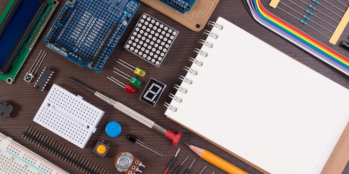
- A notebook is essential. Get a spiral or bound notebook to record your circuits, tests, and procedures.
- You’ll also need a scientific calculator. Some math is part of design, so get used to it. The math is not that bad, mainly just putting numbers in formulas and making the calculation.
- Get some test equipment. You can’t design successfully without building a prototype and testing it. You’ll need a standard digital multimeter (DMM), an oscilloscope, and a signal generator. (This expense is probably the main reason for not designing.) If you’re a serious experimenter, bite the bullet and make the investment. Once you get some real test gear, you’ll know the excitement of building something you designed and seeing it work.
- Breadboards. Those solderless prototyping boards are popular and easy to use. Get several in different sizes.
- A power supply. You’ll need a DC supply to power your prototype. Many experimenters use batteries like four AA cells in series to get six volts or a common nine volt battery. A variable supply is best, like the one I use in Figure 1.
- A workbench. A table or desk where you can leave your project set up between work sessions.
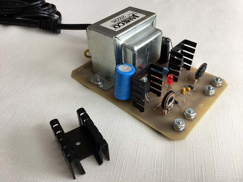
FIGURE 1. I use this dual voltage ±1.5V to ±30 variable power supply that comes as a kit from Jameco.
I know test equipment is expensive, but you do have some alternatives. For years, I used a pre-owned scope that I bought for less than $100. You can probably find one online for a good price.
A good alternative if you’re just starting out is a virtual instrument (VI). This is a device that’s a combination of a DMM, a scope, a signal generator, and a power supply all in one. I used the Analog Discovery 2 device from Digilent (Figure 2). However, they now offer the Analog Discovery 3, which is a drop-in replacement for the AD2. Go to their website to check the AD3 out. It has all those things in it. It’s used in combination with a computer that does the measurement calculations and provides a good readout screen. Plus, it’s far less expensive than most scopes alone. You’ll love it.
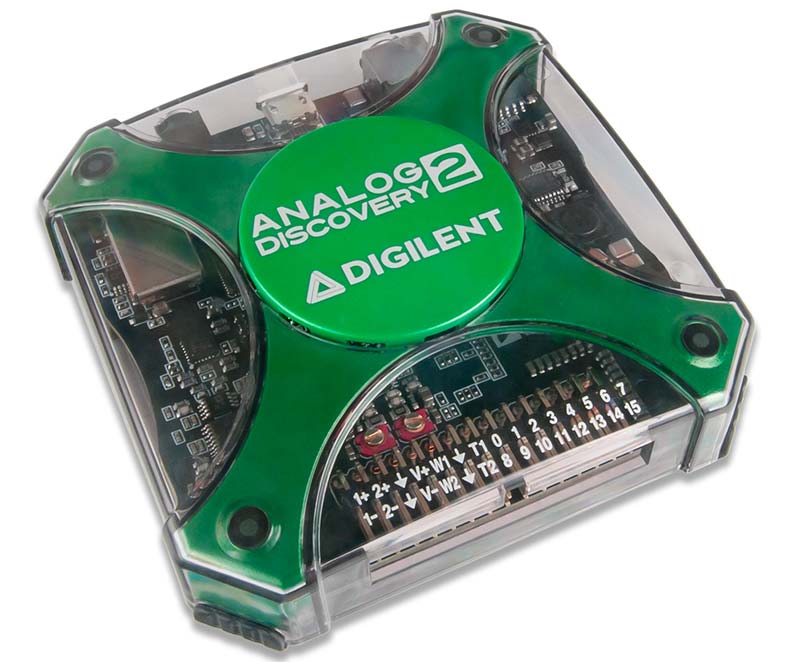
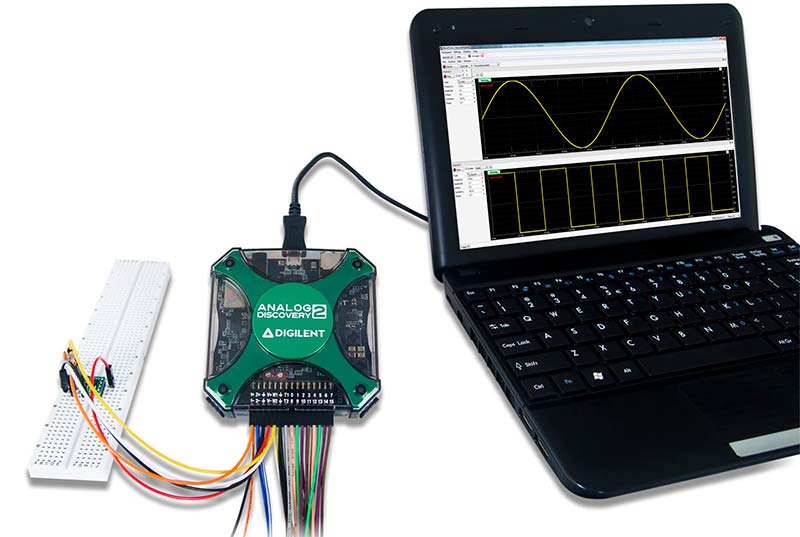
FIGURE 2. This is the Digilent Analog Discovery 2 that contains a scope, DMM, function generator, power supplies, and some impressive software to make this a great virtual instrument.
One Approach to Design
Unless you’re a genius or something, you probably can’t just envision a circuit and make it work. You need background and/or experience. If you’re a bit short on those things, the procedure given here will get you going with your own designs. Here are my recommendations:
- Research your objective. Use relevant books, articles, or whatever else is available to investigate circuits and specifications. Do some extensive online searches. Educate yourself. Build a library of relevant design related books.
- Look for a relevant integrated circuit (IC) to do the job. There are very few electronic circuits that have not been put into IC form. Chances are you won’t have to design it. Just buy the IC and put it into service according to the manufacturer’s datasheet or app notes. Create some innovative uses for existing chips.
- Copy, adopt, or reproduce any existing circuits you find, then modify them to fit your design requirements. Why re-invent the wheel? Most things you can probably think of have already been designed. Find that circuit or product, reverse engineer it, and modify the circuit or device to meet your needs and specs.
- Combine parts of different circuits to produce something new and different. Use one circuit from one source and another circuit from a different source. Mix and match.
- Use any existing modules, subassemblies, or kits to solve the problem, thereby eliminating the need to design. It’s often possible to meet your objective without ever getting out the calculator or breadboard. Do system rather than circuit design.
- Use any outside design resources. Online design software tools are abundant. Semiconductor companies are good resources for online calculators. Others are from universities and independent sources. Seek them out.
- Always build a physical prototype of your circuit. Of course, you can simulate it with modeling software like Multisim to see if it works. However, you really need to build it and test it yourself to be sure.
- Design, build, and test each circuit separately in a multi-circuit design to ensure that each circuit works by itself first before you combine them.
- The more you design and the more you build, the more you’ll learn and the better you’ll get.
The first step is to define what you want to design. Write out a description in your notebook. Include features and specifications. Next, do an Internet search for what you want to design. Be specific in stating that you want a schematic if possible. Look through any books or magazines you have. The goal here is to find something close to what you want, then modify it to meet your objectives.
A Design Example
I have an antenna that (according to the book I used to build it) has an impedance of RL = 450 ohms. I want to match that up with my transmitter that has a RS = 50 ohm output impedance. The idea is that maximum power is transferred when the load and transmitter output impedances match up. The frequency is 7,000 kHz or 7,000,000 Hz.
I searched impedance matching and found lots of reference material. Apparently, what I needed was an L network with an inductor and capacitor to make the two impedances compatible.
Several references gave the formulas to use to calculate the inductor and capacitor values. (When you do your own search, print out several of these for later study and direction.)
Another search turned up some Z matching calculators. These are online tools to help you with the design. Just plug in the values you know, and the calculator gives you the L and C values.
There are four possible L network configurations. Two are high-pass filter versions and the other two are low-pass filter configurations. Choose the low-pass version as it will help eliminate any harmonics or other undesirablesignals from the output. (These are shown in Figure 3.)
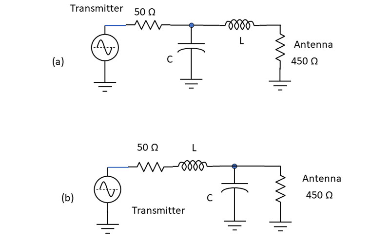
FIGURE 3. The low-pass filter L matching networks.
Notice that you need to choose the one where the source (or transmitter output) impedance RS is less than the load impedance RL or RS < RL.
Looking at some of the resources from my searches, I found the following formulas for finding L and C. I’m only showing part of the calculations as a guide. I hope you’ll do the calculations yourself.
XL = √[ (RS RL) – (RS)2] = 141.42Ω
XC = (RS RL)/XL = 159.1Ω
Once you find these reactances, you need to rearrange the formulas to calculate the L and C values. Go ahead and use your scientific calculator to make the calculations.
XL = 2πfL = 141.42Ω
L = XL/2πf = 3.217 µH
XC = 1/2πfC = 22500/141.42 = 159.1Ω
C = 1/2πXC = 1.43 x 10-10 = 143 x 10-12 = 143 pF
The online calculators I found are listed in the sidebar. I entered my values of RS = 50 ohms, RL = 450 ohms, and a frequency of 7,000 kHz. The values I received for the L network in Figure 3a were:
L = 3.2 µH and C = 143 pF.
No surprise here as that confirms your own calculations.
These values of L and C are not standard, so are hard to come by. You can probably find capacitors that are close enough. You can put capacitors in parallel to get the desired value. You may have to make your own inductors as there are not as many standard inductor values. If you want to make your own inductor, that is another design project.
As part of the design, you need to specify the ratings on the capacitor and inductor. If the transmitter puts out 100 watts, you’ll have a healthy voltage on the capacitor. In the circuit of Figure 3b, if you’re delivering 100 watts to the 450Ω antenna load, then the voltage across the load and capacitor is:
Since P = V2/R then V = √(PR) = 212V
Be sure your capacitor has a voltage rating greater than that.
As for the inductor, it should be wound with heavy wire to withstand the current. You probably should make your own air wound (no magnetic core) inductor. Use some #12 or #14 wire so the coil will be self-supporting. Go online and find the formulas for winding your own coil.
Where to get parts is always an issue. You’ll need to develop some sources of your own, but I typically use one of the online vendors like All Electronics or Jameco. Big distributors like Digi-Key, Mouser, or Avnet also have what you need. If it’s a special part, go search online for it.
In Perspective
Overall, this is a simple design, but as you can see it’s a challenge. So, it’s exciting for would-be engineers. If you’re an incurable tinkerer like many of us, you’ll be anxious to try something else. How much fun can you have?
Suggestion
If you want to know more about design like this, consider getting a copy of my new book, Practical Electronic Design for Experimenters, just recently published by McGraw-Hill. It covers all the basic circuits for both analog and digital. Once you read the book and do some of the projects, you’ll be able to say as many engineers do, “Now I are one.” NV
Online L Network Impedance Calculators
www.easycalculation.com/engineering/electrical/l-matching-network.php
www.leleivre.com/rf_lcmatch.html
www.changpuak.ch/electronics/calc_18.php
www.analog.com/en/design-center/interactive-design-tools/rf-impedance-matching-calculator.html
My new McGraw-Hill book, Practical Electronic Design for Experimenters will show you how to design most common electronic circuits.
This book is available in our webstore: Practical Electronic Design for Experimenters