Sawtooth Generator
Question:
Could you please show me how to make a variable-frequency sawtooth generator?
A Devoted Reader
Answer:
You didn’t say if you wanted a digital or analog circuit, so I will give you both. A sawtooth wave is characterized by a positive-going linear voltage ramp concluded with a sharp drop to zero (Figure 1a). One way to generate a sawtooth is to slowly charge a capacitor via a constant current source, then quickly discharge the capacitor by shorting it out. By repeating this process, a sawtooth waveform is created.
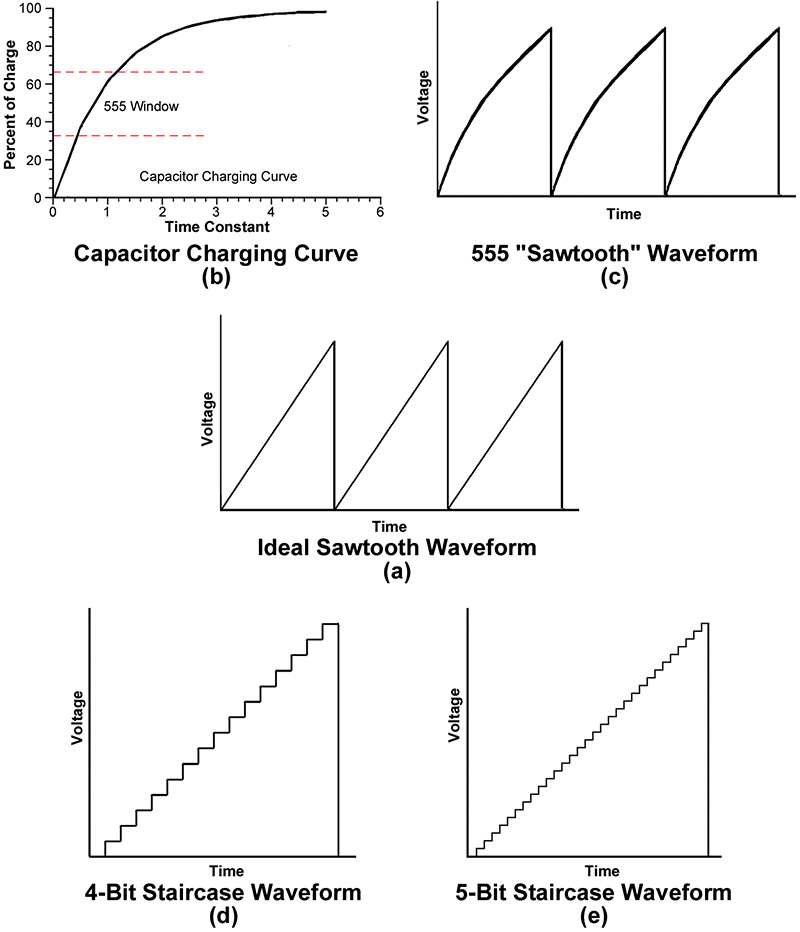
But constant-current sources can be complex — especially if you want to make it adjustable. In lieu of a constant current source, a fixed resistor is often used to limit the cap’s charging current. However, the voltage across a charging capacitor using a fixed resistor isn’t linear. It starts off fast and finishes slowly, creating the waveform you see in Figure 1b. But by selecting a section of the curve that is more or less linear — as shown by the red dashed lines — we can generate a pseudo sawtooth. A 555 timer is an astable oscillator that exploits the charging and discharging of a capacitor. It has its trip points — the points where the cap starts to charge and ends charging — at 1/3 and 2/3 the working voltage, creating the waveform shown in Figure 1c. Not perfect, but good enough for most electronics designs.
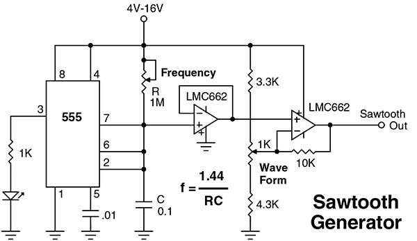
The waveform is then buffered (Figure 2) and conditioned. The Frequency pot changes the frequency and the Wave Form control adjusts the wave to keep the top and bottom of the waveform from being clipped.
A more linear sawtooth waveform can be generated using a digital up counter with weighted outputs. Look at the sawtooth generator in Figure 3. The 4516 binary counter has BCD outputs (1, 2, 4, 8) that represent values from 0 to 16 in increments of 1. Let’s set the current of the 1 output (Q0) to 40 µA by placing a 130K resistor on pin Q0 to ground. This means that every time Q0 goes high, 40 µA will flow through the resistor.
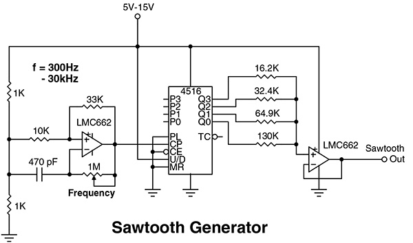
Now let’s set the current of output 2 (Q1) to 80 µA — twice as much current as Q0. When Q0 is on and Q1 is off, 40 µA will flow. When Q0 is off and Q1 is on, 80 µA will flow. But when both Q0 and Q1 are on, 120 µA will flow — three times the amount of current through Q0 alone. Does that sound like the number 3?
By setting Q2 and Q3 to equal 160 µA and 320 µA, respectively, we can represent all the values from 0 to 16 using currents. These currents are summed at the node of a non-inverting op-amp and output as a voltage. Notice that again the sawtooth waveform isn’t exactly a linear ramp, but a staircase of small individual voltage steps, as shown in Figure 1d. You can increase the resolution and remove the coarseness of the waveform by increasing the number of steps from four bits to five bits using a 4518 (Figure 1e). The greater the number of binary digits, the better the resolution of the sawtooth waveform.
The input frequency (LMC662 oscillator) determines the frequency of the sawtooth waveform using the formula f = 1/2n where n is the number of weighed outputs.
Comments