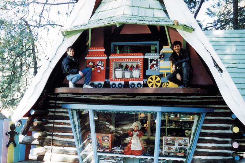
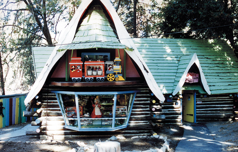
Several years before Disneyland opened their doors (and coined the name "animatronic"), there was a wonderful little theme park which opened in the San Bernardino mountains in California. It was called "Santa's Village."
This little park featured a myriad of unusual and imaginative attractions including a constantly frozen pole of ice (the North Pole, as it were) and a mine shaft which rumbled and shook producing a stream of candy "ore" for everyone to eat. I'm told that Disney "imagineers" would often visit and hang out at Santa's Village, and that they particularly enjoyed the imaginative noncommercial feel of the place.
Though Santa's Village was a very humble park in size and sophistication, I was so impressed on my visit that I asked if they'd like to add a little high tech to the usually low-tech animation that they featured.
A year later (things can take a while at the North Pole), the phone rang and I was asked by what I assume to be Elves to have a meeting. Santa had more important things to do, like handing out candy, so I was told to meet the manager "out in the mushroom patch." There, sitting out in the woods on giant cement mushrooms and amidst the din of happily screaming kids, we worked out the idea for the animated Christmas train. I have to tell you, this is my kind of office meeting! Should I ever have an office (something I strive to avoid), I hope it too will be outside!
While we were building and installing the train, we were further impressed with Santa's office protocol. For example, all work was allowed to come to a screeching halt when new cookies came out of the oven (an event which you could smell from anywhere in the park), and no one there seemed to have a name. Most people I met were known only as "painter" or "baker" or whatever job they did. I was truly saddened that such a unique place had to close their doors in recent years. But that's another story ...
The train we built for Santa's Village successfully entertained thousands of kids in the years it was there. It's now my pleasure to detail its workings for you, and to suggest that you become the neighborhood Santa by adding this surprisingly simple-to-build, yet very high-quality animation to your home or office.
Also, in this article, we'll be describing in detail how to use MIDI signals to control servos! This is something that I feel will truly provide you with the "keys to the kingdom" for any animatronic or robotic project you have ever dreamt of! If you already do Christmas with lights, then believe me, this magic train will be the coup de grais!
MIDI-Operated Servo Controller Circuit
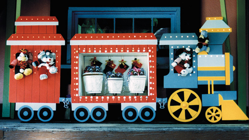
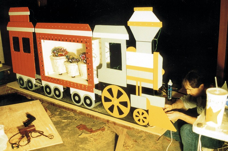
The Christmas train (shown in the photos here at Santa's Village) features moving wheels, smoke, and lights, as well as three animated singing Christmas presents. Before we go into detail on construction of the train itself, let's first discuss the control system. By the way, I'll also have several notes at the end of this article that suggest alternative controls for the less ambitious.
Principle of Operation
The moving parts of this animated project are operated by DC positional servos of the type popularly used in radio-controlled models, and often written about in Nuts & Volts. These servos are ideal for small animations, since they are low in cost, readily available, and provide quite a lot of torque from a small package. The photo in Figure 1 shows an FP-S148 servo from Futaba — probably the most common brand available worldwide — next to a quarter dollar to give an idea of its size.

FIGURE 1.
Model servos typically have a three-wire cable which requires 5V DC on the red wire, 0V on the black wire, and a pulse train of amplitude 3V to 5V on the white wire. The position of the servo is determined by the duration of the pulses on the white wire over a range between about one and two milliseconds with the mid-position of the servo corresponding to pulses of about 1.5 milliseconds. The pulses must be repeated frequently to keep the servo position updated, with a rate of about 50 pulses per second being suitable.
In this project, a microcontroller is used to generate control pulses for up to eight servos at any one time. Pulses are timed to last between 0.992 and 2.008 mS with a timing resolution of 8 mS which corresponds to a servo positional resolution of one part in 128. From practical experiments, this has been found to be about the same as the mechanical accuracy of a typical servo, so there is no need for any better resolution than this.
To operate the servos in the animation project together, we need a means of recording and playing back movement commands and communicating these to the servo controller. This is where the MIDI (Musical Instrument Digital Interface) protocol is ideal, since most home PCs can be used to record, edit, and playback MIDI signals. Also, software is available to do this in synchronization with a sound track to make a complete animation system. We'll go into more detail on techniques for recording your shows later.
The servo controller accepts signals from its MIDI input socket and responds to the 'Control Change' messages that it receives. Control Change messages are typically used to adjust the volume, panning, modulation depth, etc., of a musical performance but, in this case, we use them to adjust the positions of the servos. Up to 128 different Control Change messages can be transmitted on any one of 16 MIDI channels, giving the potential to control up to 2,048 different servos all at the same time from a single MIDI data source. Clearly, this should be enough to work just about any animation project!
In addition to proportional servos, there may also be a need in an animation for simple on/off controls, such as lights or solenoid-driven motion. To simplify the operation of such devices, the servo controller provides four logic outputs in parallel with the first four servo outputs. A logic output will be low when its corresponding Control Change value is zero and high when the Control Change is non-zero. Any of these outputs can be used as an alternative to a servo output when just an on/off function needs to be controlled.
Control Change messages can usually be stored in a MIDI file by entering them manually using MIDI editing software and then playing them back in real time to view the effect achieved. However, this is very time-consuming and difficult to get a feel for how the animation is going to look as the values are entered.
A much simpler and quicker way to generate the Control Change messages is to record them in real time from a MIDI data source, such as a musical keyboard which has pitch bend and modulation wheels. Even more convenient is to plug a standard joystick into the PC which is running the MIDI editing software, allowing direct control over several servos at once as the movements are recorded. A program to allow this is freely available for download from www.j-omega.co.uk.
Circuit Description
Figure 2 shows the schematic of the complete servo controller used in the animation project.

FIGURE 2. Schematic
A standard MIDI cable plugs into the five-pin DIN socket, CONN1, and receives signals from the controlling computer. Electrical isolation from the computer is provided by optocoupler U1 in conjunction with current-limiting resistor R1 and reverse protection diode D1 to avoid problems with earth loops and to prevent damage to the computer in the event of a fault in the servo controller. R4 pulls up U1's open-collector output to give a 5V logic signal.
The MIDI bit stream from U1 is fed to the serial data input of IC1, a pre-programmed PIC16C63 microcontroller available from www.j-omega.co.uk. The controller software responds to Control Change messages on one of 16 MIDI channels selected by switches SW1a to SW1d and input pull-up resistors R3 to R6 and uses the value of these messages to set the pulse duration of the eight servo outputs on PL1 to PL8. The four logic on/off outputs are on PL10 to PL13, each one using an I/O line of the microcontroller.
There are 128 possible Control Change messages which could be transmitted to the servo controller on its selected MIDI channel, but it only responds to eight of these at any one time. Using switches SW2a to SW2d with pull-up resistors R7 to R10 selects which eight messages control the servo outputs. If the switches represent the binary value 0, then the servo outputs respond to Control Change messages 0 to 7. If the switches represent binary value 1, then Control Change messages 8 to 15 are used, and so on. With four switches, the eight servos can be selected to any one of 16 groups, meaning that the entire 128-controller range is covered.
Each servo is controlled by an output from IC1, which are standard 5V logic outputs. IC1 is clocked at 4 MHz by crystal XTAL1 with loading capacitors C1 and C2. Capacitors C3 to C7 provide high-frequency power supply decoupling. The entire circuit runs at 5V, which powers both the controller components and the servos, and is connected via PL9. The circuit for the controller can be built onto a single-sided printed circuit board measuring three-inches square, the artwork for which is shown in Figure 3a and 3b.
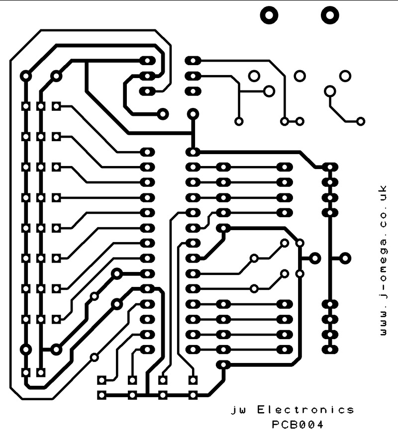
FIGURE 3A.
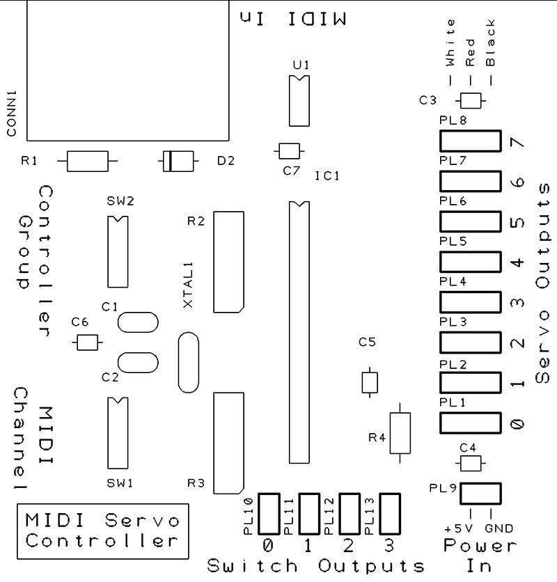
FIGURE 3B.
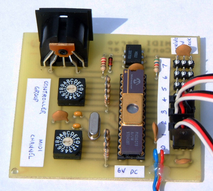
FIGURE 4.
Okay, Let's Build A Train
The train's construction can be seen here and is simple and straightforward. (The original train sketch was done by artist Marvie Harris.) Simply transfer the sketch (shown in Figure 5) to two sheets of thin plywood, then cut the plywood to shape using a jigsaw and paint.
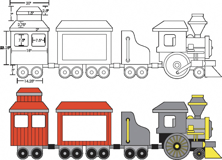
FIGURE 5.
There are several easy methods for transferring the sketch to wood. Using an overhead projector to project the image on the wood, then tracing it is one easy way, or having the whole train printed out in color by a sign making company will work well. In the latter case, the sign material can simply be laminated to the wood and your train will be ready to go!
The train, of course, is also simple enough to be copied by freehand drawing. The wheels are cut from some thin sheet aluminum. Draw, then cut the circles out using tin snips. The paint scheme shown is simple and common latex house paints were used. The box car (which carries the singing presents) also includes a wooden box behind the window to act as a stage. (If you live in a cold or wet climate, Plexiglas can be used as a window.) Finally, to add to the flashy nighttime look, holes were drilled along all windows and tops of cars. White Christmas lights are then set in place through the holes with a little silicon glue.
Since the wheels were cut out from light aluminum, they are very easy to spin from behind. I simply attached them to some low RPM (20 to 40 RPM) 24V motors. Many Nuts & Volts advertisers carry these, including one of my favorites — All Electronics. You can certainly use timer motors as well, but low voltages are a good idea for something that is outdoors. For Santa's Village, I used 24V AC syncron motors which are expensive (about $60.00 each), but tend to last till the bearings wear out!
The motor axle can be attached to the wheels in many ways. Even simple silicon glue may hold. I personally drilled a center hole, then held the axle to the wheel with an "L" bracket. The entire train was anchored to a heavy piece of plywood laying on the roof using large "L" brackets from behind. (These are the type intended to support heavy shelving.)
Adding Life
The train all by itself makes a nice display, but now it's time to add life! Figure 6 shows a front and side view of the singing Christmas presents.
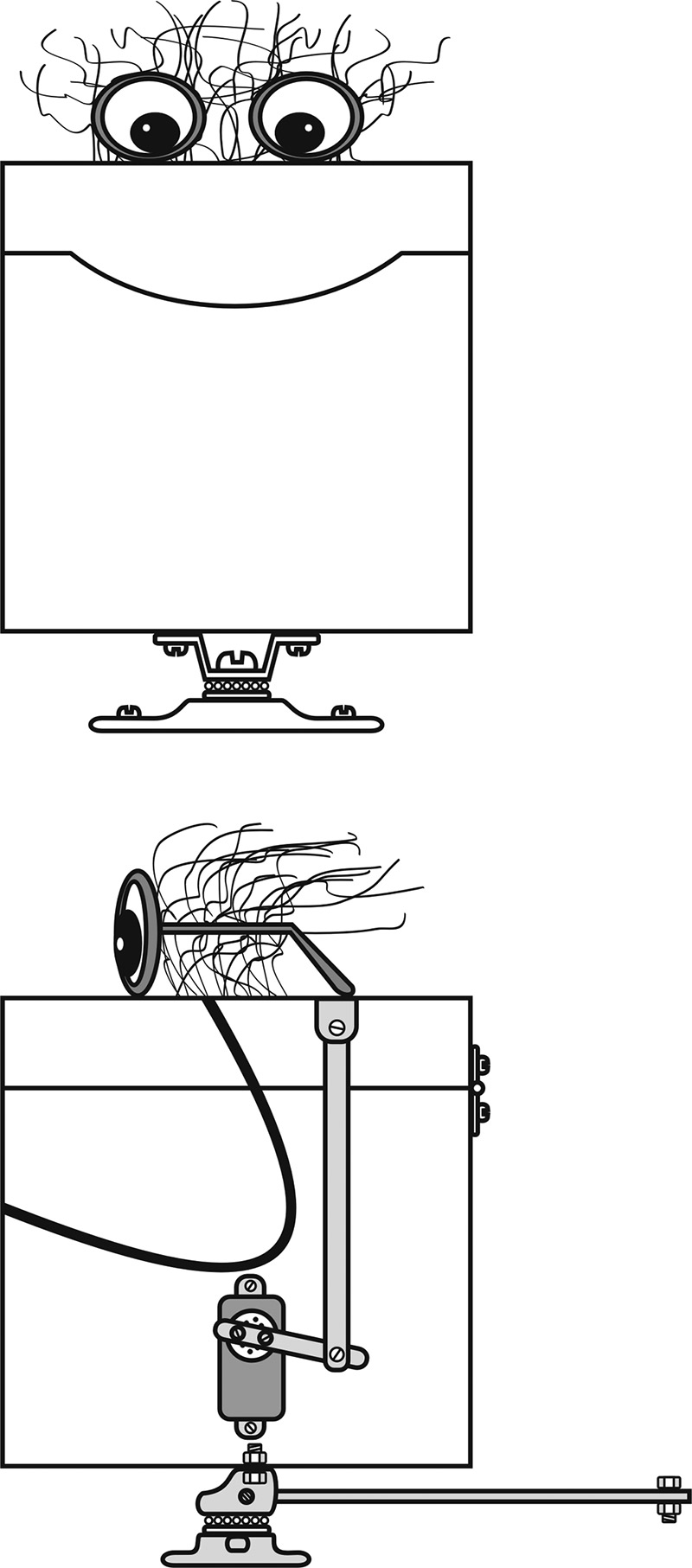
FIGURE 6.
I actually made these on quite a number of occasions, and I tried all kinds of different boxes depending on where they were to be displayed. In most cases, you can just use cardboard boxes! Wrap them as you would any gift, but glue the paper to all sides of the box. I then cut the box so that my present would always have a smile as shown, and clear coated them with some spray lacquer for durability. So that the mouth-moving mechanism wouldn't be seen (don't you hate it when you can see the gizmo working the animatronic), a piece of black felt is draped in front as shown.
One set of gifts I made actually hid the mechanism with an illusion. I made a false back in the box where the actuator was hidden. This made it look like the mouth was levitating open with nothing moving it!
The entire box is mounted to a ball-bearing base so that it can swivel to the music. I made these bases by buying wheel casters at Home Depot, removing the wheel and bending the forks as shown to screw into some wood glued to the bottom of the box. I also attached a long arm to the back of the ball-bearing base as shown. This arm can be pulled back and forth by a servo in the same manner as the mouth is shown being raised. Figure 7 shows a circuit (courtesy the late TJ Byers) that you should have when building anything with servos. This simple circuit will let you move a servo manually by turning a pot and, therefore, allow you to "test on the fly" and gauge the placement of your servos with regard to torque and range of motion.

FIGURE 7.
The portion of the circuit shown inside the dotted line is just something I slapped together for fun. This little add-on will allow you to hook this circuit to the speaker output of any audio source and the servo will move as if talking along with audio. If your servo occasionally moves the wrong direction, try adding a small electrolytic cap (.68 or so) between the two leads on the output side of the 8 ohm to 1K coil. The 10K pots control sensitivity to incoming audio and servo position, respectively. The positioning pot becomes a control for dialing in range of motion when used as a mouth circuit.
The bodies of the actual Santa's village gifts were made from the most durable thing I could think of ... Tupperware containers! These were then painted with special decorative spray paint from a crafts store that looked like festive wrapping (a primer of tool dip spray was used since Tupperware is hard to paint). The final touches to create the illusion of life included children's sunglasses, lots of glitter, and streamers for hair. Rolling eyeballs — ala my hero the Cookie Monster — were also added. Since the whole top of the box moves, the eyes roll around with each motion giving you a "motion freebee."
Cheap Tricks (Simplified Construction)
As mentioned earlier, there are simplified methods for building a less lifelike, but still attractive display. One is to use the simple talking circuit we just outlined and to attach the signal out wire (pin3) to each of the gift's servos. This will create three gifts talking in unison when connected to any recording. Next, attach a simple low RPM motor and cam to rock the presents from behind. The train’s wheels and lights can be simply left on, and the overall effect will still be good.
But hey, I'd say "go for the gusto" on this one!
Note: Remember if you’re using the talking circuit, a good idea is to record music and audio on one stereo channel, and just a tone to trigger mouth movements on the other channel. The channel with the tone is connected to the gifts (T1), and the channel with music and voice goes to the loudspeaker. By separating the channels in this way, you can get nearly perfect mouth movements. (As opposed to having music or sound effects accidentally triggering the mouth circuit.)
Let The Show Begin!
There is a myriad of software available for recording and playing back MIDI. I personally use "Cakewalk" software since I also use it for writing music. Find a program that allows audio recording, as well as MIDI recording.
Other than installing the software, all that is needed by your computer is a MIDI cable that connects to your game card and has two five-pin din connectors. (One for "MIDI In," and one for "MIDI Out.") The "MIDI In" connector can be fitted to any keyboard for input, or you may want to use a joystick by downloading the free software on our web page.
The learning curve is pretty short with this software, and it allows you to do a lot of neat things like record sound, FX, and music all on different tracks at different times and play them back together. After getting the audio portion of your show done (my gifts sang a "Smurfing Christmas" and some other songs), you can start animating your characters!
Start by working one character just as you would a puppet using your keyboard or joystick. You'll be able to listen to the music and dialog while he moves. The MIDI program will capture all your motions and keep them synchronized with the audio tracks on future playbacks. You have an unlimited amount of tries to get it "perfect" since you can just hit "undo" any time you have a bad take.
Each time you get a perfect take, you can then move on to the next character or feature to animate and build your show in layers! When you're all done, you'll have a perfect, complex show with audio and animation saved to disk. This will run from a simple double click on an icon, or can be "endlessly" looped.
Once your show is ready, you have other options for playback. Even my "old" 486 did alright running MIDI software. So here's a use for that old computer in the basement! You can even run your display without a PC: MIDI sequencers can be linked to an audio source.
Some Quick Notes
Remember that you have four regular "off and on" outputs on the MIDI board. These can be used with relays to start and stop smoke (from a fog machine) and to spin the train's wheels or flash the lights.
Also, remember that you can hook more than one servo up to the same signal line, so if you'd like all your characters to move in unison, this can be automatic and you can use the additional outputs to animate other features! Almost any movement is possible! It is a simple matter to give any character moving eyes, eyelids (carved ping pong balls make great eyelids), glasses, or even wiggling bow ties!
With these basics, it's time for Disney to watch out! Let your imagination run!
Happy Holidays! NV
Parts List for Servo Test Circuit
| D1 |
1N34A |
| IC1 |
555 |
| Q1 |
2N2222 or any general-purpose transistor |
| R1 |
4.7K |
| R2 |
68K |
| R3 |
1K |
| R4, R5 |
10K pot |
| C1 |
.22 µF capacitor |
| C2 |
.01 cap |
| T1 |
8 ohm to 1K transformer |
Component List
| CONN1 |
Five-pin DIN 180-degree PCB mount socket |
| D1 |
1N4148 or similar signal diode |
| U1 |
H11L1 logic output optoisolator |
| IC1 |
Pre-programmed PIC16C63 microcontroller |
| XTAL1 |
4 MHz parallel resonant quartz crystal |
| R1 |
220R 5% 0.25W carbon film resistor |
| R2, R3 |
22K 5% 0.125W quad SIL resistor array |
| R4 |
5K6 5% 0.25W carbon film resistor |
| S1, S2 |
16-way BCD rotary switch |
| C1, C2 |
22 pF ceramic capacitor |
| C3 to C7 |
100 nF ceramic capacitor |
| PL1 to PL13 |
Three-way SIL pin header, 0.1" pitch |