 Although cell phones, global positioning system receivers, satellite television systems, and the AM/FM radio in your car perform completely different functions, the receivers used in these systems are all based on a concept first developed by the American electrical engineer Edwin Armstrong during the waning days of the first World War. Almost a century after its introduction — except for sophisticated approaches such as software radio that involve advanced digital signal processing techniques — Armstrong’s “superheterodyne” or “superhet” design reigns supreme in communications electronics.
Receiver Design Evolution
To understand the superhet’s superiority over previous designs or architectures, it is helpful to review a few of the difficulties of one receiver design that it replaced — that of the “Tuned Radio Frequency” or TRF receiver, shown in Figure 1. The TRF receiver came about from the common sense observation that since radio signals coming from the antenna are extremely weak, a more sensitive receiver might be obtained by amplifying the radio frequency (RF) signals immediately following the antenna. And given the poor performance of early vacuum tube amplifiers, if one stage provided insufficient gain, then cascading more stages should lead to a receiver that became progressively more sensitive (able to receive even weaker signals) and selective (able to select the desired signal and reject the others).
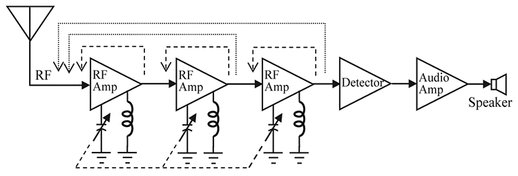
FIGURE 1. Tuned Radio Frequency Receiver (TRF) block diagram showing intra-stage feedback (dashed line) and inter-stage feedback (dotted line).
Unfortunately, these ideas contain a number of troubling flaws that ultimately proved fatal to widespread application of this approach.
As far as increasing sensitivity goes, a problem immediately occurs because the radio frequency amplifiers necessary for each stage of the TRF receiver are inherently unstable. This is because in all electronic amplifiers — be they of the vacuum tube or transistor type — a small amount of capacitive coupling exists between the input and output of the device itself.
This intra-stage feedback is shown as the dashed line between the input and output of each stage in the figure. Several techniques, such as neutralization, may be employed to extend the frequency range of an individual TRF stage, but the difficulties of avoiding oscillation in tuneable, high-gain RF stages mount directly as the operating frequency increases.
Additionally, inter-stage feedback occurs when the output of one amplifier stage appears at the input of a preceding amplifier stage. The dotted lines in the figure show the multiple feedback paths that may exist in a TRF receiver with only a few stages. Either increasing the gain of the individual stages or adding more stages to get more gain increases the inter-stage feedback, as well as the potential for oscillation.
Avoiding this problem requires great care to shield and decouple each stage from all of the others. Like intra-stage feedback, inter-stage feedback worsens as the operating frequency increases, compounding the difficulties of constructing sensitive, adjustable TRF receivers that will operate without oscillation over large frequency ranges.
Improving the selectivity of the TRF design introduces another set of problems. The most vexing one is related to a quirk in the parallel RLC tuned circuit, or “tank,” used to select the desired operating frequency. Unfortunately, the bandwidth of the parallel tank circuit is not constant with frequency, but increases approximately with the square root of the operating frequency.
For example, a TRF receiver tuned to 0.5 MHz might have a parallel RLC tank circuit designed to just receive a 10 kHz bandwidth signal. But the tank’s bandwidth increases to about 17 kHz — much wider than the desired signal — when the receiver is retuned to 1.5 MHz.
Another difficulty is associated with the mechanically linked tuned circuits that allow for simultaneous adjustment of the tuned circuits as the operating frequency changes. Any mechanical or electrical mismatch during tuning serves to decrease overall receiver selectivity.
Armstrong’s Design
The problems associated with the TRF receiver seem intractable, but Edwin Armstrong was a genius at thinking “out of the box” in order to solve complicated problems. Armstrong reasoned that if achieving a stable cascade of variable high-frequency amplifiers was a problem, he would avoid it. Armstrong built a cascade of fix-tuned amplifiers at a low frequency where a large amount of stable gain was easy to obtain. Then he preceded this amplifier cascade with a frequency translator or mixer stage in order to convert or “heterodyne” the desired signal to the new “intermediate frequency” or IF. Armstrong called this new receiver (which used heterodyning to translate signals to a fixed, lower intermediate frequency for reception) the “superheterodyne” receiver, as shown in the block diagram in Figure 2.
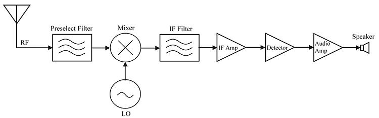
FIGURE 2. Architecture of Armstrong’s superheterodyne receiver.
Designing an AM superhet receiver for the commercial broadcast band is a good way to better understand the operation of Armstrong’s superheterodyne receiver. The AM broadcast band contains 117 10 kHz-wide channels spaced between 530–1,700 kHz. In order to generate a fixed IF of 455 kHz (the standard IF for the AM broadcast band since the 1930s), the local oscillator (LO) must be able to generate a signal that tracks exactly 455 kHz above the incoming signal, or between 985–2,155 kHz.
The mixer takes these two signals, the RF and the LO, and outputs the difference frequency, LO – RF, to the IF amplifier. The fix-tuned IF amplifier selects the incoming 10 kHz wide signal while rejecting any signals present in adjacent channels above and below 455 kHz. For example, in order to receive a 1,000 kHz RF signal, the LO must generate a 1,455 kHz signal in order to translate the incoming signal to the 455 kHz IF. After amplification, the IF signal is then demodulated to detect the desired audio signal from the radio frequency carrier, amplified by the audio amplifier, and then applied to headphones or a speaker to convert the electrical signal into an acoustic one so you again can hear the broadcast (see Figure 2).
There is another signal that can produce a 455 kHz output from the mixer when the LO is tuned to 1,455 kHz. That signal is called the “image frequency,” and it is located at LO + IF or 1,910 kHz. Note that because the image frequency produces the same 455 kHz IF when applied to the mixer as the desired signal, it is necessary to eliminate the image frequency before it reaches the mixer. This is done with a parallel-tuned tank circuit, also known as a preselector, that follows the antenna.
It is important to realize that in the superhet receiver, the requirements on the preselector are greatly diminished compared to the tuned circuits in the TRF receiver. In the superhet, the preselector only needs to select one of two signals that are separated by 910 kHz — a relatively simple task — while the tuned circuits in the TRF are required to separate signals as close as 10 kHz across the entire frequency range of the receiver.
Circuit Description
Now that we understand the basic operation of Armstrong’s superhet receiver, we are ready to build a simple radio that incorporates all of these concepts. The schematic of a receiver I call the Simple Superhet is shown in Figure 3. I chose this name because I believe the circuit is just about the simplest, fully functional superheterodyne receiver one can construct with just a handful of parts.
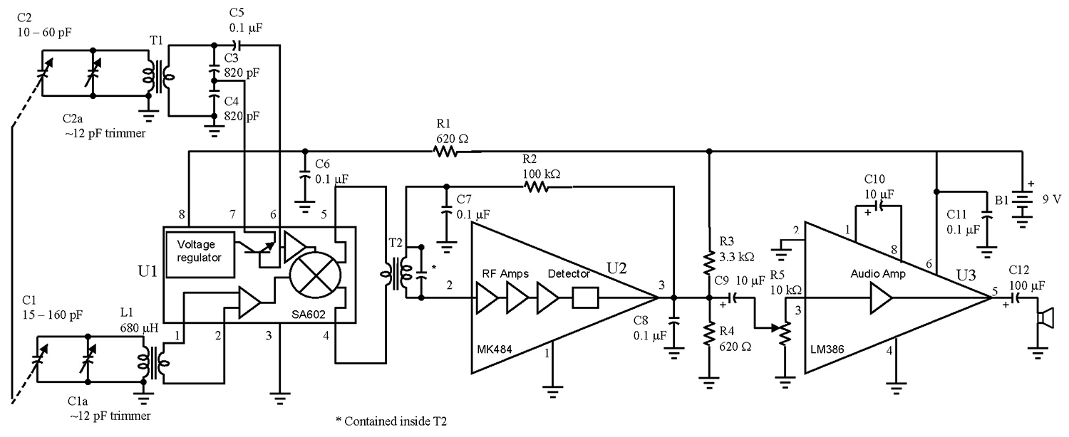
FIGURE 3. Schematic diagram of the Simple Superhet AM broadcast band receiver.
Many electronics experimenters will be familiar with the three ICs used in this design as they are commonly found in many homebrew receiver projects. Let’s take a look at them one at a time before we see how they work together in the Simple Superhet.
The SA602AN (which is a pin-for-pin equivalent to the NE602N originally produced by Signetics) is an eight-lead dual in-line package (DIP) intended for low-power, high performance communications systems. It contains an onboard oscillator transistor that requires only a few passive components to implement the LO function. The IC also contains a double-balanced mixer that produces the IF output by combining the internally generated LO with the input RF signal.
Amplification at the IF and detection of the audio signal is handled by the MK484 (originally produced as the ZN414Z by GEC Plessey). This IC contains a 10 transistor TRF receiver circuit packaged in a three-pin TO-92 package. The MK484 implements a TRF receiver by cascading three high-gain RF amplifiers followed by a transistor detector.
This IC provides a very high power gain of 72 dB using a supply voltage of only about 1.5V! Although the IC functions from 150 kHz to 3,000 kHz, manufacturer’s performance curves show that maximum gain for small input signals occurs very near the 455 kHz IF — a perfect match for the Simple Superhet!
The final IC — also an eight-lead DIP — is the LM386N-1 low voltage audio power amplifier. This IC is designed for use in low voltage consumer applications and can provide gains up to 46 dB. This amplifier provides sufficient output power to drive a small speaker when the receiver is tuned to local stations.
Construction
Now that we’ve introduced the three ICs, let’s return to Figure 3 and see how to combine them to form the Simple Superhet. The primary of the ferrite antenna loopstick, L1, and the variable capacitor, C1, form a parallel tank circuit that “preselects” the desired signal, while attenuating any image signal that might also be present. The antenna loopstick also converts the electromagnetic field of incoming radio waves into a small RF voltage that is applied through the loopstick’s secondary winding to the input of the double-balanced mixer, pins 1 and 2 of U1.
Variable capacitor C2, transformer T1 (red can), and capacitors C3–C5, along with the oscillator transistor internal to the SA602 form a Colpitts oscillator that serves as a tuneable LO for the Simple Superhet. The Colpitts oscillator creates oscillations by feeding back the output signal from the emitter of the oscillator transistor (pin 7) to the base of the oscillator transistor (pin 6) through the capacitive voltage divider formed by C3 and C4.
Note that the primary of the red can (side with three pins) is connected to C2, while the secondary (side with two pins) is connected to C3 and C4. R1 and C6 form a decoupling network that keeps RF and LO signals off of the power supply line, while also limiting the supply voltage for the SA602 to less than eight volts as required for this IC. The output of the SA602 is the desired IF signal which appears as a balanced output signal across pins 4 and 5.
Transformer T2 (yellow can) and the MK484 IC form the heart of the IF amplifier. It is important to observe that in this application the IF transformer is turned around “backwards” in order to convert the balanced output of the mixer into a high impedance, singled-ended output to drive the MK484. Note that in this case the primary of the yellow can (side with three pins) is connected to pin 2 of the MK484, while the secondary (side with two pins) is connected between pins 4 and 5 of the SA602. The single IF filter is extremely selective because the equivalent load resistance on the primary of T2 is very large.
Continuing with the operation of the MK484, resistors R3 and R4 form a voltage divider that reduces the 9V supply voltage to approximately 1.6V necessary to power the IC. Resistor R2 and capacitor C7 provide decoupled bias to the IC’s input, while capacitor C8 shorts any RF present at the IC’s output to ground.
The operation of the LM386 audio amplifier is very straightforward. Potentiometer R5 attenuates the audio signal to provide the user with a volume control. Capacitor C10 maximizes the amplifier’s audio gain, capacitor C11 decouples the supply voltage, and capacitor C12 blocks DC current from the speaker coil.
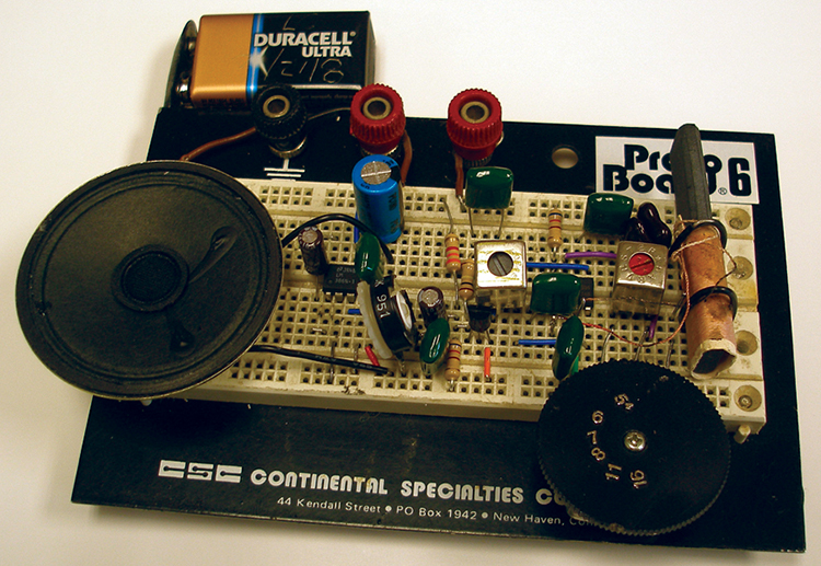
FIGURE 4. Prototype of the Simple Superhet receiver. Do not force the IF transformer into the board as the plastic case may split. Instead, solder a short wire extension onto each pin to insert into the corresponding hole to complete the connection.
A good strategy for receiver construction is to start at the speaker and build towards the antenna. This allows the builder to aurally verify circuit operation as work progresses. Additionally, a very fast way to construct this circuit is by plugging the components into a proto board as shown in Figure 4. Once circuit operation is verified, it is straightforward to construct the circuit on something more permanent, such as a PC board construction shown in Figure 5.
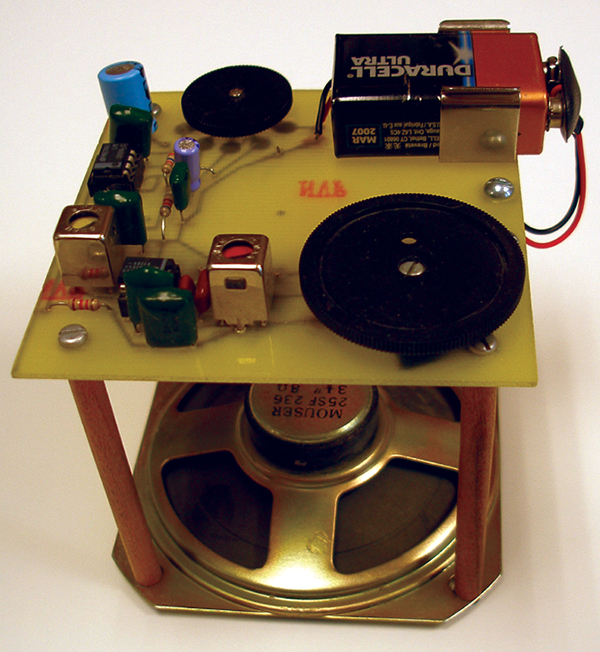
FIGURE 5. An example of a PCB implementation of the superhet receiver with a 3-1/2” speaker used as the base. The PCB is supported above the speaker by 3” long wooden dowels. The loopstick antenna (not visible) is mounted underneath the PCB using a small metal bracket.
Begin constructing the audio amplifier by wiring in the LM386 IC, speaker, R5, and C9–C12. Apply power to the IC along with an audio tone from a signal generator to the free end of C9. You should be able to hear a healthy tone at the speaker with volume adjustment provided by R5. Next add the MK484, R2–R4, C7–C8, and the yellow IF can. Connect a low level 455 kHz tone modulated signal to the secondary of the IF can, apply power to the circuit, and the demodulated tone should be plainly audible on the speaker.
Adjust the screw on the IF transformer to obtain maximum volume with the modulated 455 kHz signal. If you don’t have a 455 kHz signal generator available, center the screw near the mid-range position and proceed. Complete the Simple Superhet by wiring in the SA602 along with the remaining components.
Testing and Calibration
The radio is finished, but it is necessary to properly align the RF and LO circuits before it will receive any stations. With a small non-metallic screwdriver, unmesh the LO and RF trimmer capacitors C1a and C2a that are found on the back of the plastic-cased variable capacitor C1-C2. Next, tune an AM/shortwave receiver to 985 kHz and place it next to your circuit, or capacitively couple a frequency counter to pin 4 or 5 of the SA602 to monitor the oscillator frequency.
Apply power to your circuit and rotate the variable capacitor C1-C2 fully counter-clockwise (CCW). Then adjust the screw on the LO transformer T1 (red can) to spot the signal from the oscillator at 985 kHz. Rotate the variable capacitor fully clockwise (CW) and then tune trimmer capacitor C2a until you can spot the signal at 2,155 kHz using the monitor receiver or frequency counter.
Repeat the above steps once or twice adjusting T1 at the low frequency end and C2a at the high frequency end. You have successfully aligned the LO stage when full CCW and CW rotation of the variable capacitor produces signals between 985 kHz and 2,155 kHz, respectively. (Note: Stray capacitance, particularly if you use proto board construction, may limit the frequency spread you can achieve to less than the full range).
Align the RF preselector by tuning the variable capacitor to a station near the lower end of the AM band, or loosely couple a signal from a signal generator into the ferrite antenna using a small loop of wire. Very slowly slide the ferrite bar in and out of the loopstick antenna until the loudest audio signal is produced. Then secure the ferrite bar in place with a small wedge of paper.
Retune the radio to a station (or the signal generator, if used) near the upper end of the AM band. This time, very carefully adjust trimmer capacitor C1a until the loudest audio is produced. Repeat this procedure, adjusting the ferrite bar at the low frequency end and the trimmer capacitor at the high frequency end, to maximize volume for stations located at both ends of the AM band. This completes construction, testing, and alignment of the Simple Superhet receiver.
From Here
Here are some other things you can try on your own:
- Try increasing or decreasing the number of turns on the secondary of the ferrite antenna bar to improve receiver sensitivity. If your loopstick antenna did not come with a secondary coil, you can wind your own secondary coil using about a dozen turns of fine magnet wire over the existing primary turns.
- Substitute the “white can” or “black can” for the yellow can IF transformer to see how sensitivity and/or selectivity change.
- Increase or decrease R3 one or two standard resistor values to see how it affects the gain and stability of the MK484 IF amplifier. (Note: Keep the voltage at pin 3 of the MK484 below 1.8V to avoid destroying the IC!)
- Advanced experimenters may modify the basic design to build a superhet receiver for other interesting frequency bands such as Citizen’s Band or WWV. Proceed by constructing a crystal oscillator or Phase Locked Loop (PLL) frequency synthesizer for the LO, as well as modifying the preselector to properly receive signals in the desired frequency range.
I hope you have as much fun building, using, and modifying your Simple Superhet receiver as I have had with mine! NV
Digging Deeper
- Superheterodyne receiver design and operation is discussed in great detail in Chapter 4 of Tomasi, Wayne, Electronic Communications Systems Fundamentals Through Advanced, 5th Edition, Prentice Hall Career & Technology, Englewood Cliffs, NJ 2003.
- For an interesting discussion of why tuned-input/tuned-output amplifiers are so difficult to stabilize see Young, Paul H., Electronic Communication Techniques, 5th Edition, Prentice Hall, Upper Saddle River, NJ 2004.
- The operation of the SA602AN oscillator and mixer are discussed in Chapters 11 and 12 respectively of Rutledge, David B., The Electronics of Radio, Cambridge University Press, Cambridge, UK 1999.
Sources
ICs, loopstick antenna, and tuning capacitor
www.angelfire.com/electronic2/index1/index.html
IF and oscillator transformers
http://www.elexp.com/ProductListing.aspx?CatId=6bec9a32-0578-4598-9e9a-ee813a8bd132
Datasheets for ICs
http://pdf.datasheetcatalog.com/datasheet/RECTRON/MK484.pdf
www.datasheetcatalog.com/datasheets_pdf/S/A/6/0/SA602AN_01.shtml
www.datasheetcatalog.com/datasheets_pdf/L/M/3/8/LM386.shtml
PARTS LIST
|
| ITEM |
DESCRIPTION |
| Resistors (1/4 watt) |
| R1, R4 |
620 Ω |
| R2 |
100K |
| R3 |
3.3K |
| R5 |
10K potentiometer |
| Capacitors (25 volts or higher) |
| C1-C2 |
Two-section, ganged variable capacitor with trimmers.
Antenna section, 15-160 pF; oscillator section, 10-60 pF |
| C3, C4 |
820 pF mica or Hi-Q ceramic |
| C5, C6, C7 |
0.1 µF monolithic ceramic |
| C8, C11 |
0.1 µF monolithic ceramic |
| C9, C10 |
10 µF electrolytic |
| C12 |
100 µF electrolytic |
| Inductors |
| L1 |
680 µH ferrite loopstick antenna |
| T1 |
AM BC band local oscillator transformer (red can) |
| T2 |
455 kHz intermediate frequency transformer (yellow can) |
| Semiconductors |
| U1 |
SA602AN (or NE602N) LO/mixer |
| U2 |
MK484 (or ZN414Z) TRF receiver/detector |
| U3 |
LM386N-1 audio amp |
| Miscellaneous |
| B1 |
9V battery and snap connector |
| Knobs |
|
| 8 W speaker |
|