Optoelectronic circuits — which respond to either visible or invisible (usually infrared) light levels — are widely used in modern domestic and commercial security systems.
Optoelectronic security circuits come in three basic types, the first of which is the simple ‘visible-light-level’ type that reacts when a light level goes above or below a preset value.
The second type is the light-beam alarm, which reacts when a person, object, or animal breaks or reflects a projected visible or infrared (IR) light beam.
The third type is the passive infrared (PIR) detector, which is sensitive to the heat-generated infrared light radiated by the human body, and thus reacts when a human or other large warm-blooded animal comes within the sensing range of the PIR detector.
A range of practical optoelectronic circuits of the ‘visible light’ type are described in this part of our series; practical IR ‘light-beam’ and PIR circuits will be described in the next part.
VISIBLE-LIGHT-LEVEL CIRCUITS
LDR BASICS
Most optoelectronic circuits that are designed to respond to normal visible light use a cadmium sulphide (CdS) LDR (light-dependent resistor) as their light-sensing element or photocell. Figure 1 shows an LDR’s circuit symbol and basic construction, which consists of a pair of metal film contacts separated by a snake-like track of light-sensitive cadmium sulphide film; the structure is housed in a clear plastic or resin case.
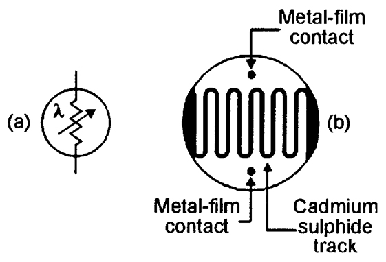
FIGURE 1. LDR symbol (a) and basic structure (b).
Figure 2 shows the typical photoresistive graph that applies to an LDR with a face diameter of about 10mm; the LDR acts as a high resistance (typically hundreds of kilohms) under dark conditions, falling to about 900R at a light intensity of 100 Lux (typical of a well-lit room) or about 30R at 8000 Lux (typical of bright sunlight).
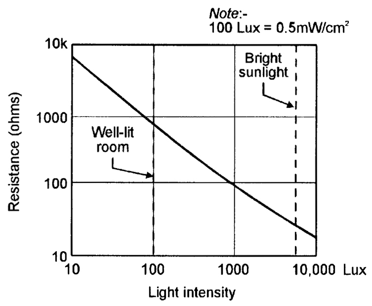
FIGURE 2. Typical characteristics curve of an LDR with a 10mm face diameter.
Note that although most of the practical circuits shown throughout this ‘VISIBLE-LIGHT-LEVEL’ section of this article are shown using an ORP12 photocell, they will, in fact, work well with almost any general-purpose LDRs with face diameters in the range 3mm to 12mm.
SIMPLE RELAY SWITCHES AND ALARMS
The simplest ‘visible-light-level’ security circuits are the types that are designed to activate when the light level goes through a large change, such as from near-dark to a moderately high level, or vice versa. Some circuits of this type function as ‘light-activated’ units that switch on a relay or safety mechanism or sound an alarm when light enters a normally dark area such as the inside of a storeroom, wall safe, or security case, etc.
Other circuits are designed as ‘dark-activated’ units, and activate when the light level drops well below some nominal value. Figures 3 to 7 show some simple circuits of these types.
The Figure 3 circuit is that of a simple non-latching, light-activated relay switch. Here, R1-LDR and R2 form a potential divider that controls the base-bias of Q1. Under dark conditions, the LDR resistance is very high, so negligible base-bias is applied to Q1, and Q1 and relay RLA are both off.

FIGURE 3. Simple non-latching light-activated relay switch.
When light enters the normally dark area and falls on the LDR face, however, the LDR resistance falls to a fairly low value and base-bias is applied to Q1, which thus turns on and activates the relay and its RLA/1 contacts, which can be used to control external circuitry. The relay can be any 12V type with a coil resistance of 180R or greater.
The simple Figure 3 circuit has a fairly low sensitivity, and has no facility for sensitivity adjustment. Figure 4 shows how these deficiencies can be overcome by using a super-alpha-connected pair of transistors in place of Q1, and by using sensitivity control RV1 in place of R2; this circuit can be activated by LDR resistances as high as 200K (i.e., by exposing the LDR to very small light levels), and draws a standby current of only a few microamps under ‘dark’ conditions.
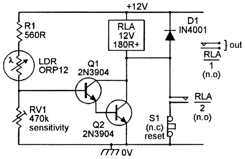
FIGURE 4. Sensitive self-latching light-activated relay switch.
The diagram also shows how the circuit can be made to give a self-latching action via relay contacts RLA/2; normally-closed push button switch S1 enables the circuit to be reset (unlatched) when required.
Figure 5 shows an LDR used in a simple dark-activated circuit that turns relay RLA on when the light level falls below a value that is pre-set via RV1. Here, R1 and LDR act as a potential divider that is fed with a pre-set DC voltage from RV1 and generates an output voltage that rises as the light level falls, and vice versa.
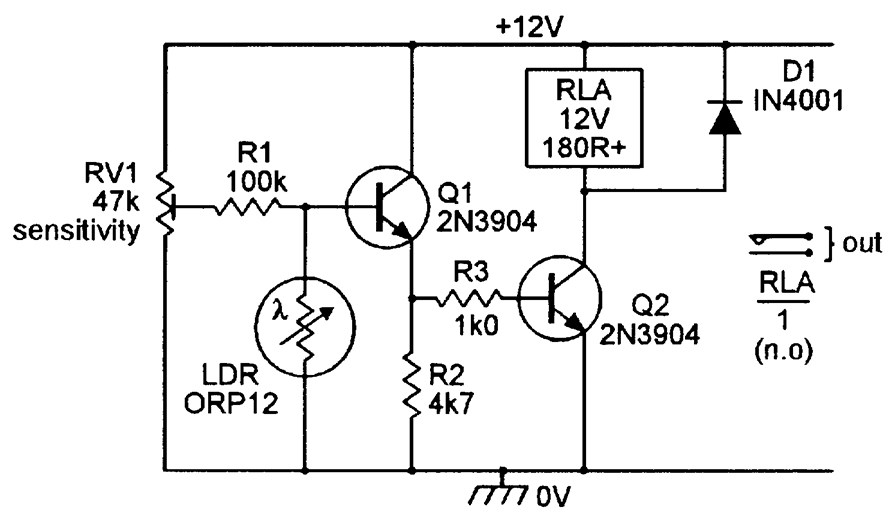
FIGURE 5. Simple dark-activated relay switch.
This generated voltage is buffered by emitter follower Q1 and is used to control the relay via common-emitter amplifier Q2 and current-limiting resistor R3. Thus, when the light level falls below the pre-set value, the R1-LDR divider’s output voltage reaches a large enough level to activate both Q1 and Q2, and the relay turns on.
Figures 6 and 7 show simple SCR (silicon controlled rectifier) circuits that — under the light-sensitive ‘alarm’ condition — activate an ordinary self-interrupting electromechanical alarm bell. This bell must (when the specified C106D SCR is used) consume an operating current of less than 2A, and the circuit’s supply voltage must be at least 1V greater than the bell’s nominal operating voltage.
The Figure 6 circuit is a simple non-latching one, in which the alarm bell is wired in series with an SCR that receives its gate drive from the positive supply rail via the R1-LDR-R2 potential divider. Thus, under dark conditions, the LDR resistance is very high, so negligible gating voltage appears across R2, and the SCR and alarm are both off.
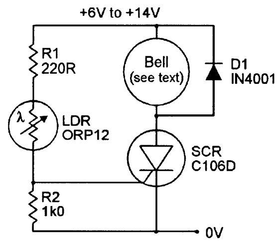
FIGURE 6. Simple light-activated alarm bell.
When light enters the normally dark area and falls on the LDR face, however, the LDR resistance falls to a fairly low value, and if this value is below roughly 10K, the LDR passes enough current to gate the SCR into the ‘on’ mode, thus sounding the alarm bell.
Most LDRs (including the ORP12) give a resistance of less than 10K when exposed to low-intensity room lighting or the light of a torch, so this circuit operates as soon as it is exposed to a moderate amount of illumination.
Note in the above circuit that, although the SCR is a self-latching device, it automatically unlatches each time that the bell enters a self-interrupt phase (and the SCR anode current drops to zero). Consequently, the alarm bell automatically turns off when the light level falls back below the SCR’s ‘trip’ level.
The Figure 6 circuit has a fairly low sensitivity and has no facility for sensitivity adjustment. Figure 7 shows how these deficiencies can be overcome by using RV1 in place of R2 and by using Q1 as a buffer between the LDR and the SCR gate; this circuit can be activated by LDR resistances as high as 200K (i.e., by exposing the LDR to very small light levels).
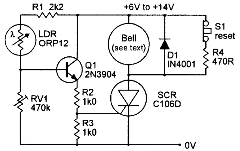
FIGURE 7. Improved light-activated alarm bell with self-latching facility.
This diagram also shows how the circuit can be made self-latching by wiring R4 across the bell so that the SCR anode current does not fall to zero as the bell self-interrupts. Switch S1 enables the circuit to be reset (unlatched) when required.
SIREN-OUTPUT ALARMS
The Figures 2 to 7 circuits are designed to give either alarm-bell or relay outputs. In some applications, an electronic ‘siren sound’ output may be preferable, and Figures 8 and 9 show low-power (up to 520mW) speaker-output circuits of this type. The Figure 8 circuit gives non-latching operation and develops a pulsed-tone output signal. The Figure 9 circuit gives self-latching operation, and develops a monotone output signal. Both circuits are designed around a 4001B CMOS IC.
In the Figure 8 circuit, the IC’s two left-hand gates are wired as a low-frequency (6Hz) gated astable multivibrator that is activated via the light-sensitive LDR-RV1 potential divider, and the two right-hand gates are wired as a gated 800Hz astable that is activated by the 6Hz astable.

FIGURE 8. Non-latching light-activated alarm with pulsed-tone output.
Under dark conditions, the LDR-RV1 output voltage is high and both astables are gated off, and the circuit consumes a fairly low standby current, but under bright conditions the LDR-RV1 output voltage is low and both astables are activated, with the left-hand astable gating the 800Hz astable on and off at a 6Hz rate, thus generating a pulsed 800Hz tone in the speaker.
In the self-latching Figure 9 circuit, the IC’s two left-hand gates are wired as a simple bistable multivibrator that can be activated (SET) by a high voltage on the output of the light-sensitive LDR-RV1 potential divider, and the two right-hand gates are wired as a gated 800Hz astable that is activated by the bistable’s output.
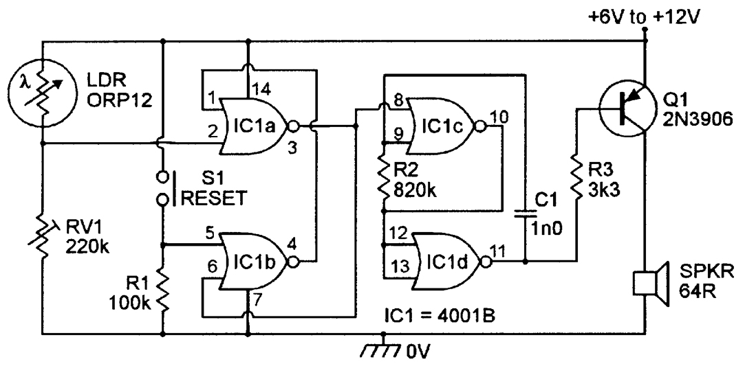
FIGURE 9. Self-latching light-activated alarm gives monotone output.
Under normal dark conditions, the output of the LDR-RV1 divider is low, the bistable output is in the high ‘RESET’ state, thus gating the astable off, and the circuit consumes only a small standby current. When the LDR is exposed to light, however, the LDR-RV1 junction goes high, flipping the self-latching bistable into the SET mode, in which its output goes low and gates on the 800Hz astable, thus generating a monotone speaker signal.
Once it has been activated, the circuit can only be turned off again by removing the LDR’s illumination and briefly closing RESET switch S1, at which point the bistable output resets to the high state and the astable is gated off again.
Note that the trigger points of the Figures 8 and 9 circuits occur at the point at which the LDR-RV1 junction voltage swings above or below IC1’s ‘transition’ voltage value, which lays somewhere between one-third and two-thirds of the supply voltage value.
In practice, the light-trigger points of these circuits are not greatly affected by supply voltage variations. Also note that, when using the output stages shown in the diagrams, these two circuits each give maximum output powers of only 520mW into the 64R speakers, but that these powers can be boosted to as high as 13.2 watts by replacing the Q1 output stages with the power-boosting circuits shown in Figures 21 or 22 in Part 3 of this series.
PRECISION RELAY-SWITCHING CIRCUITS
The relay-switching circuits of Figures 3 to 5 are fairly sensitive to variations in supply voltage and temperature, and are not suitable for use in precision light-sensing application. Figure 10 shows a very sensitive light-sensitive relay-driving circuit that is not influenced by such variations, and is thus suitable for use in many precision light-sensing applications, and which turns the relay on when the light level rises above a pre-set value.
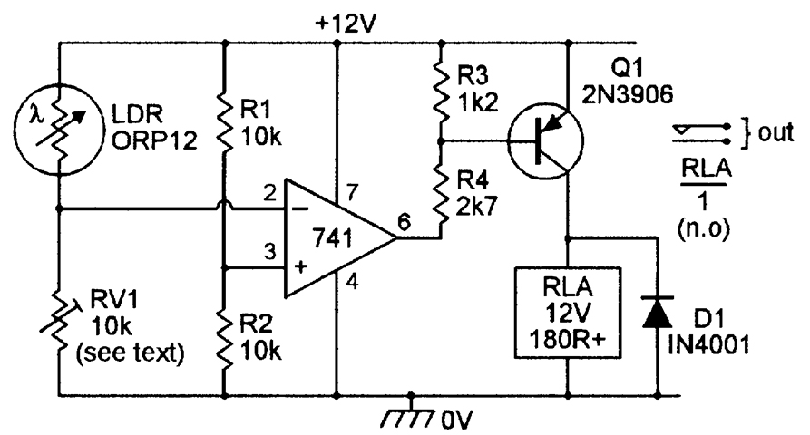
FIGURE 10. Precision light-activated relay switch.
In this case, LDR-RV1 and R1-R2 are connected in the form of a Wheatstone bridge, and the op-amp and Q1-RLA act as a highly sensitive balance-detecting switch. The bridge balance point is quite independent of variations in supply voltage and temperature, and is influenced only by variations in the relative values of the bridge components.
In Figure 10, the LDR and RV1 form one arm of the bridge, and R1-R2 form the other arm. These arms can actually be regarded as potential dividers, with the R1-R2 arm applying a fixed half-supply voltage to the non-inverting input of the op-amp, and with the LDR-RV1 divider applying a light-dependent variable voltage to the inverting terminal of the op-amp.
In use, RV1 is adjusted so that the LDR-RV1 voltage rises slightly above that of R1-R2 as the light intensity rises to the desired trigger level and, under this condition, the op-amp output switches to negative saturation and thus drives RLA on via Q1 and biasing resistors R3-R4. When the light intensity falls below this level, the op-amp output switches to positive saturation and, under this condition, Q1 and the relay are off.
The Figure 10 circuit is very sensitive and can detect light-level changes too small to be seen by the human eye. The circuit can be modified to act as a precision dark-activated switch (which turns the relay on when the light level falls below a pre-set value) by either transposing the inverting and non-inverting input terminal connections of the op-amp, or by transposing RV1 and the LDR.
Figure 11 shows a circuit using the latter option. This diagram also shows how a small amount of hysteresis can be added to the circuit via feedback resistor R5, so that the relay turns on when the light level falls to a particular value, but does not turn off again until the light level rises a substantial amount above this value (this action helps prevent spurious switching due to passing shadows, etc., in automatic lighting-control circuits). The hysteresis magnitude is inversely proportional to the R5 value, being zero when R5 is open circuit.
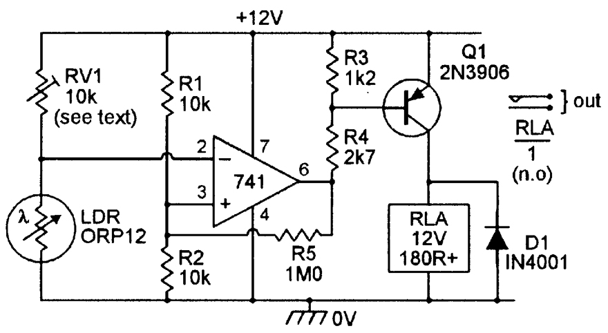
FIGURE 11. Precision dark-activated switch, with hysteresis.
Figure 12 shows how a precision combined light-/dark-activated switch (which activates a single relay if the light intensity rises above one pre-set value or falls below another pre-set value) can be made by combining the ‘light’ and ‘dark’ switch circuits of Figures 10 and 11.
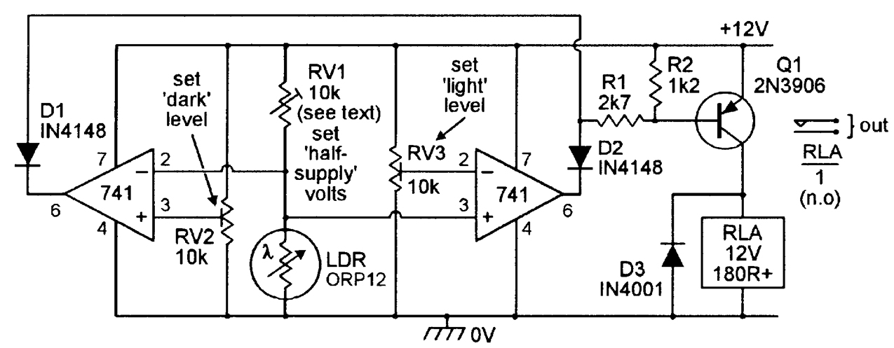
FIGURE 12. Combined light-/dark-activated switch with a single relay output.
To set up this circuit, first pre-set RV1 so that roughly half-supply volts appear on the LDR-RV1 junction when the LDR is illuminated at the mean or normal intensity level. RV2 can then be pre-set so that RLA turns on when the light intensity falls to the desired dark level, and RV3 can be pre-set so that RLA activates when the light rises to the desired ‘bright’ level.
Note in the Figures 10 to 12 ‘precision’ circuits that the basic RV1 value should be roughly double that of the LDR resistance value at the desired ‘trigger’ light levels, so that RV1’s slider is reasonably close to its central position under this condition. Thus, the RV1 value may have to be reduced below 10K if a circuit is set to trigger under very bright conditions, or may have to be increased above 10K if used to trigger under very dark conditions.
PRECISION ALARM-SOUNDING CIRCUITS
The basic op-amp based precision circuits of Figures 10 to 12 can easily be used in conjunction with some of the alarm-bell activator or siren-sound generator circuits already shown in this article, to make various precision alarm-sounding circuits. Figure 13, for example, shows modified versions of the basic Figure 6 and 10 circuits combined to make a precision light-activated alarm bell circuit that can easily be changed into a dark-activated unit by simply transposing RV1 and the LDR. Note that the op-amp’s supply line is decoupled from that of the bell via D3 and C1.

FIGURE 13. Precision light-activated alarm bell.
Similarly, Figure 14 shows modified versions of the basic Figure 8 and 10 circuits combined to make a precision light-activated pulsed-tone alarm with built-in hysteresis.
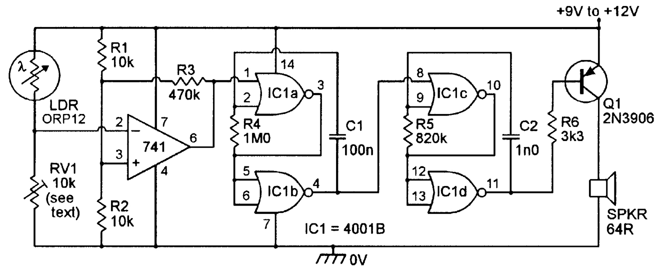
FIGURE 14. Precision light-activated pulsed-tone alarm with hysteresis.
The hysteresis is controlled by R3, which can have its value altered to obtain different hysteresis values, or can be removed if hysteresis is not needed.
LIGHT-BEAM ALARM CIRCUITS
SIMPLE VISIBLE-LIGHT DESIGNS
A light-beam alarm system consists of a focused light-beam transmitter (Tx) and a focused light-beam receiver (Rx), and may be configured to give either a direct-light-beam or a reflected-light-beam type of optical contact operation.
Figure 15 shows the basic elements of a direct-light-beam type of alarm system, in which the sharply focused Tx light-beam is aimed directly at the light-sensitive input point of the Rx unit, which (usually) is designed to activate an external alarm or safety mechanism if a person, object, or piece of machinery enters the light-beam and breaks the optical contact between the Tx and Rx.
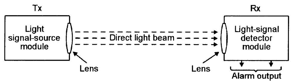
FIGURE 15. The basic elements of a direct-light-beam type of alarm system.
Figure 16 shows a very simple example of a lamp-and-LDR direct-light-beam system that activates an alarm-bell if the beam is interrupted. The beam is generated via an ordinary electric lamp and a lens, and is focused (via a ‘collector’ lens) on to the face of an LDR in the remote Rx unit, which operates as a dark-activated alarm.
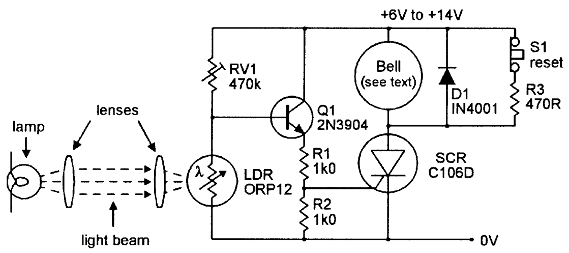
FIGURE 16. Simple direct-light-beam alarm with alarm bell output.
Normally, the LDR face is illuminated by the light-beam, so the LDR has a low resistance and very little voltage thus appears on the RV1-LDR junction, so the SCR and bell are off. When the light-beam is broken, however, the LDR resistance goes high and enough voltage appears on the RV1-LDR junction to trigger the SCR, which drives the alarm bell on; R3 is used to self-latch the alarm.
Figure 17 shows the basic elements of a reflected-light-beam type of alarm system, in which the Tx light-beam and Rx lens are optically screened from each other but are both aimed outwards towards a specific point, so that an optical link can be set up by a reflective object (such as metallic paint or smoke or fog particles) placed at that point.
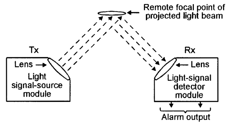
FIGURE 17. The basic elements of a reflected-light-beam type of alarm system.
This type of system is usually designed to activate an alarm when the presence of such an object is detected, but can also be configured to give the reverse action, so that the alarm activates if a reflective object is legally or illegally removed.
Units of the Figure 17 type were once widely used in conjunction with reflection-type fog and smoke detector units; Figure 18 shows a sectional view of a smoke detector unit of this type.
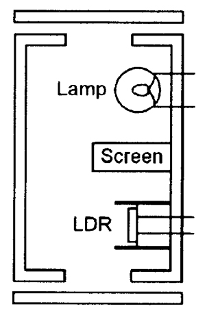
FIGURE 18. Sectional view of a reflection-type smoke detector.
Here, the lamp and LDR are mounted in an open ended but light-excluding box, in which an internal screen prevents the lamp-light from falling directly on the LDR face. The lamp is a source of both light and heat, and the heat causes convection currents of air to be drawn in from the bottom of the box and to be expelled through the top. The inside of the box is painted matt black, and the construction lets air pass through the box but excludes external light.
Thus, if the convected air currents are smoke free, no light falls on the LDR face, and the LDR presents a high resistance. If the air currents do contain smoke, however, the smoke particles cause the light of the lamp to reflect on to the LDR face and so cause a large and easily detectable decrease in the LDR resistance.

FIGURE 19. Smoke alarm with alarm bell output.
Figure 19 shows the practical circuit of a reflection-type smoke alarm that can be used with this detector; the circuit acts in the same way as the improved Figure 7 light-activated alarm circuit.
IR LIGHT-BEAM ALARMS
Simple lamp-and-LDR light-beam alarms of the types described in the last section have several obvious disadvantages in most modern security-alarm applications. Their light-beams are, for example, clearly visible to an intruder, the transmitter’s filament lamp is unreliable, and the systems are (because the transmitter’s filament lamp consumes a lot of power) very inefficient.
In practice, virtually all modern light-beam security systems operate in the invisible infrared (rather than visible light) range, and use one or more pulse-driven IR LEDs to generate the transmitter’s ‘light-beam,’ and use matching IR diodes or transistors to detect the beam at the receiver end of the system.
Our next episode in this series will give detailed descriptions of various modern IR light-beam security systems, and will also describe the operating principles of modern PIR body-detection security devices. NV