IR LIGHT-BEAM ALARM BASICS
Our last episode of this ‘Security Electronics’ series explained (among other things) the basic operating principles of visible light-beam alarm circuits, and ended by explaining that virtually all modern light-beam security systems, in fact, operate in the invisible infrared (rather than visible light) range. Use one or more pulse-driven IR LEDs to generate the tranmitter’s ‘light-beam,’ and use matching IR photodiodes or phototransistors to detect the beam at the receiver end of the system. The graph of Figure 1 conveys some useful information regarding the spectral response of the human eye, and of general-purpose and IR photodiodes and phototransistors.
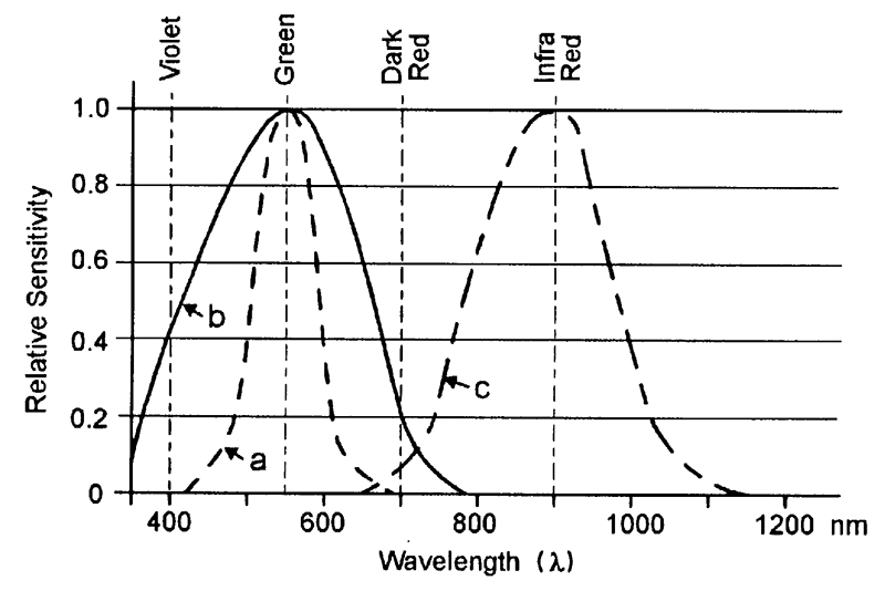
FIGURE 1. Typical spectral response curves of (a) the human eye and (b) general-purpose, and (c) IR photodiodes/transistors.
Thus, the human eye is sensitive to a range of electromagnetic light radiation; it has a peak spectral response to the color green, which has a wavelength of about 550nm, and has relatively low sensitivity to the color violet (400nm) at one end of the visible-light spectrum, and to dark red (700nm) at the other. The human eye is blind to electromagnetic light radiation beyond this narrow spectrum.
Optoelectronic semiconductor devices such as photodiodes and phototransistors have spectral responses that are determined by the chemistry of their semiconductor junction material.
General-purpose ‘light sensitive’ types have (as shown in Figure 1) typical spectral responses that straddle the human visibility spectrum, but IR types operate at a peak wavelength of about 900nm and generate an output spectrum that is well beyond the range of normal human visibility. IR light-beams are thus invisible to human eyes.
A simple IR direct light-beam intrusion detector or alarm system can be made by connecting an IR light-beam transmitter and IR receiver in the basic way shown in Figure 2.

FIGURE 2. Simple IR direct light-beam alarm system.
Here, the transmitter feeds a coded pulse-type signal (often a simple squarewave) into an IR LED that has its output focused into a fairly narrow beam (via a molded-in lens in the LED casing) that is aimed at a matching IR photodetector (phototransistor or photodiode) in the remotely placed receiver.
The system action is such that the receiver output is ‘off’ while the light-beam reaches the receiver, but turns on and activates an external alarm or other mechanism if the beam is interrupted by a person or other object.
This basic type of system can be designed to give a useful detection range of up to 20 meters when used with additional optical focusing lenses, or up to five meters without extra lenses.
Note that the simple Figure 2 light-beam alarm system works on a strict line-of-sight principle between the Tx and Rx lenses, and the alarm may thus activate if any object with a diameter greater than the smaller of the two lenses enters the beam’s line-of-sight.
Thus, a weakness of this simple system is that it can easily be false-triggered by relatively small insects entering the beam or resting on one of the lenses. The improved dual light-beam system shown in Figure 3 does not suffer from this defect.
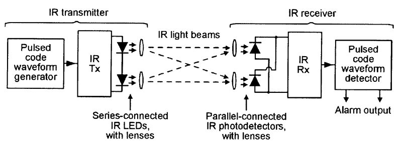
FIGURE 3. IR dual light-beam alarm system.
The Figure 3 system is basically similar to that already described, but transmits the IR beam via two series-connected LEDs that are spaced about 75mm apart, and receives the beam via two parallel-connected photo-detectors that are also spaced about 75mm apart.
Thus, each photodetector can detect the beam from either LED, and the receiver’s alarm will thus activate only if both beams are broken simultaneously, and this will normally only occur if a large (greater than 75mm) object is placed within the composite beam. This system is thus virtually immune to false triggering by insects, etc.
Note that, as well as giving excellent false-alarm immunity, the dual light-beam system also gives (at any given LED drive-current value) double the effective detection range of the simple single-beam system, since it has twice as much effective IR transmitter output power and twice the receiver sensitivity.
IR SYSTEM WAVEFORMS
IR light-beam systems are usually used in conditions in which high levels of ambient or background IR radiation (generated by natural or artificial heat sources) already exist. To enable the systems to differentiate against this background radiation, and give good effective detection ranges, the transmitter beams are invariably pulse-coded, and the receivers are fitted with matching pulse-code detection.
In practice, the transmitter beams usually use either a continuous-tone or a tone-burst type of pulse-coding, as shown in Figure 4.
IR LEDs and photodetectors are very fast-acting devices, and the effective range of an IR beam system is thus determined by the peak currents fed into the transmitting LED (or LEDs), rather than by the mean LED current.
Thus, if the waveforms of Figure 4 are used in IR transmitters giving peak LED currents of 100mA, both systems will give the same effective operating range, but the Figure 4(a) continuous-tone transmitter will consume a mean LED current of 50mA, while the tone-burst system of Figure 4(b) will consume a mean current of only 1mA (but will require a more complex circuit design).
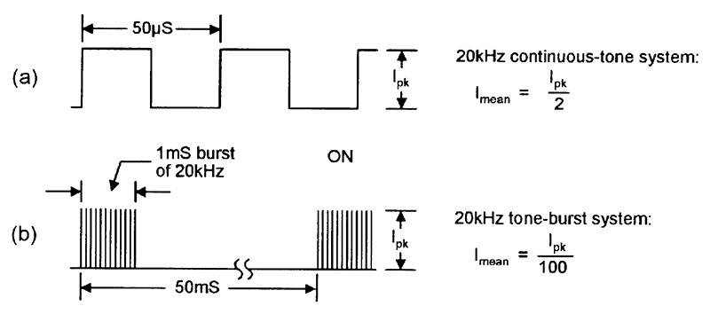
FIGURE 4. Alternative types of IR light-beam pulse-code waveforms, with typical parameter values.
The operating parameters of the tone-burst system require careful consideration, since this type of IR intrusion detecting system actually works on a ‘sampling’ principle and is usually intended to detect the presence of a human intruder.
Note that humans moving at normal walking speed take about 200mS to pass any given point, so IR light-beam systems do not need to be switched on continuously to detect a human intruder, but only need to be turned on for brief ‘sampling’ periods at repetition periods that are far shorter than 200mS (at, say, 50mS).
The actual sample period can be very short relative to the repetition period, but must be long relative to the tone frequency period. Thus, a good compromise is to use a 20KHz tone with a burst or ‘sample’ period of 1mS and a repetition period of 50mS, as shown in the waveform example of Figure 4(b).
IR SYSTEM DESIGN
The first step in designing any electronic system is that of devising the system’s block diagrams. Figure 5 shows a suitable block diagram of a continuous-tone IR light-beam intrusion alarm/detector system, and Figure 6 shows the block diagram of a tone-burst version of the system. Note that a number of blocks (such as the IR output stage, the tone pre-amp, and the output driver) are common to both systems.
The continuous-tone system (Figure 5) is very simple, with the transmitter comprising nothing more than a squarewave generator driving an IR output stage, and the receiver comprising a matching tone pre-amplifier and code waveform detector, followed by an output driver stage that can activate a device such as a relay or alarm, etc.

FIGURE 5. Block diagram of a continuous-tone IR light-beam intruder alarm/detector system.
The tone-burst system (Figure 6) is rather more complex, with the transmitter comprising a free-running pulse generator (generating 1mS pulses at 50mS intervals) that drives a 20KHz squarewave generator which, in turn, drives the IR output stage that generates the final tone-burst IR light beam.
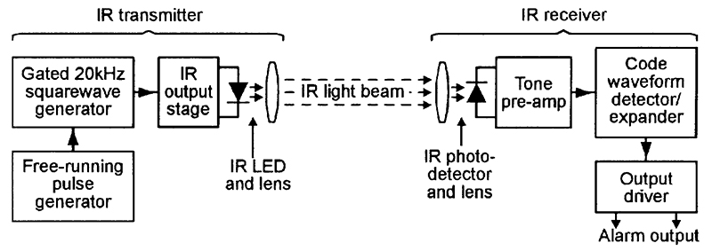
FIGURE 6. Block diagram of a tone-burst IR light-beam intruder alarm/detector system.
In the receiver, the beam signals are picked up and passed through a matching pre-amplifier and then passed on to a code waveform detector/expander block, which ensures that the alarm does not activate during the ‘blank’ parts of the IR waveform. The output of the expander stage is fed to the output driver.
IR LIGHT-BEAM TRANSMITTER CIRCUITS
Figure 7 shows the practical circuit of a simple continuous-tone dual light-beam IR transmitter. Here, a standard 555 ‘timer’ IC is wired as an astable multivibrator that generates a non-symmetrical 20KHz squarewave output that drives the two series-connected IR LEDs at peak output currents of about 400mA via R5 and Q1, and the low source impedance of storage capacitor C1.
The circuit’s timing action is such that the ON period of the LEDs is controlled by C2 and R2, and the OFF period by C2 and (R1+R2), i.e., so that the LEDs are ON for only about one-eighth of each cycle; the circuit thus consumes a mean current of only about 50mA.
The Figure 7 circuit can use either TIL38 or LD271 (or similar) ‘high power’ (100mW or greater) IR LEDs. These popular and widely-available LEDs can handle mean currents up to only 100mA or so, but can handle brief repetitive peak currents of up to at least 2.5A.

FIGURE 7. Simple continuous-tone IR light-beam transmitter.
Figure 8 shows the outline and connections of these devices, which have a molded-in lens that focuses the output into a radiating beam of about 60° width; at the edges of the beam, the IR signal strength is half of that at the beam’s center.

FIGURE 8. Outline and connections used by the LD271 and TIL38 IR LEDs.
Minor weaknesses of the IR output stage (Q1 and R3 to R5) of the Figure 7 circuit are that it has a very low input impedance (about 300R), that it gives an inverting action (the LEDs are ON when the input is low), and that the LED output current varies with the circuit’s supply voltage.
Figure 9 shows an alternative universal IR transmitter output stage that suffers from none of these defects. Here, the base drive current of output transistor Q2 is derived from Q1 collector, and the Q1 circuit has an input impedance of about 5k0 (determined mainly by the R1 value).

FIGURE 9. ‘Universal’ IR transmitter output stage.
Thus, when the circuit’s input is low, Q1 is off, so Q2 and the two IR LEDs are also off, but when the input is high, Q1 is driven to saturation via R3, thus driving LED1 (a standard red LED) and Q2 and the two IR LEDs on.
Under this latter condition, about 1.8V is developed across LED1, and about 0.6V less than this (= 1.2V) is thus developed across R4, causing Q2 to act as a constant-current generator that feeds a peak collector current of 1.2V/R4 amps into the two IR LEDs. Thus, this circuit’s peak output current can be set by giving R4 an ohm’s value of 1.2V/I, where I is the desired peak output current in amps.
Figure 10 shows a 20KHz squarewave generator (made from a 555 timer IC) that can be used in conjunction with the Figure 9 output circuit to make a continuous-tone IR beam transmitter. In this case, the Figure 9 circuit’s R4 value should be at least 6R8, to limit the peak IR LED currents to less than 200mA.

FIGURE 10. 20KHz squarewave ‘tone’ generator.
Alternatively, Figure 11 shows the circuit of a tone-burst generator that gives 1mS bursts of 20KHz at 50mS intervals, and which can be used in conjunction with the Figure 9 output stage to make an IR tone-bursts transmitter.

FIGURE 11. Tone-burst (1mS burst of 20KHz at 50mS intervals) waveform generator.
Here, the IC1a and IC1b sections of a 4011B CMOS quad two-input NAND gate IC are wired as a free-running asymmetrical astable multivibrator that produces 1mS and 49mS periods; this waveform is inverted and buffered by IC1c and used to gate a 20KHz 555-type squarewave generator via D2, and this squarewave is then buffered and inverted by the final 4011B stage (IC1c), ready for feeding to the input of the Figure 9 output stage.
Note when using the Figure 11 circuit that R4 in the Figure 9 output stage can be given a value as low as 2R2, to give peak output currents of up to 550mA, but that, under this condition, the transmitter will consume a mean current of little more than 6mA.
IR RECEIVER PRE-AMP DESIGN
The basic IR input signal to an IR light-beam receiver can be picked up and converted into a proportional current by either an IR photodiode or an IR phototransistor. If a photodiode is used, it can be connected in series with a load resistor (with a typical value in the range 10K to 100K), and can be used in either of the reverse-biased configurations shown in Figure 12.
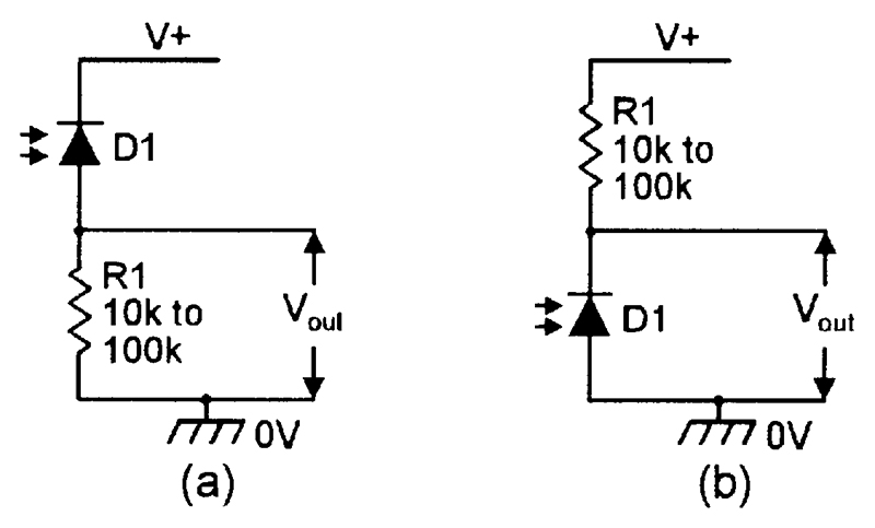
FIGURE 12. Alternative ways of using a photodiode as a light-to-voltage converter.
The diode’s basic action is such that its reverse-biased leakage current is proportional to the IR light intensity on its junction, being very low under dark conditions and relatively high when brightly illuminated; this current is converted into a proportional output voltage by R1.
An IR phototransistor can be used by connecting it in either of the basic ways shown in Figure 13(a) or (b), in which load resistor R1 has a typical value in the range 1K0 to 33K. Most phototransistors have only two externally-accessible leads (collector and emitter), but a few are three-lead types with an accessible base lead; a three-lead device can be used as a photo-transistor by connecting it in either of the basic ways already shown, or it can be used as a photodiode by wiring it in the way shown in Figure 13(c).

FIGURE 13. (a) and (b); alternative phototransistor configurations. (c); a three-lead phototransistor use as a photodiode.
Note that a phototransistor’s sensitivity is typically 100 times greater than that of a photodiode, but its maximum operating frequency (typically a few hundred KHz) is proportionally lower than that of a photodiode (typically 10s of MHz). Also note in Figures 12 and 13 that the photosensor exhibits a high sensitivity but a low cut-off frequency if R1 has a high value, and a low sensitivity but high cut-off frequency if R1 has a low value.
Figure 14 shows the practical circuit of an IR light-beam receiver that is designed for use with 20KHz continuous-tone or tone-burst single-beam or dual-beam systems, and uses IR photodiodes as signal converters. Here, the two IR diodes are connected in parallel and wired in series with R1, so that the converted IR signal is developed across R1 (note that one of these diodes can be removed if the unit is used with a single-beam IR system).
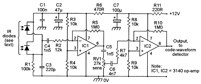
FIGURE 14. IR receiver pre-amplifier circuit.
The converted R1 signal is amplified by cascaded op-amps IC1 and IC2, which can provide a maximum signal gain of about x17,680 (= x83 via IC1 and x213 via IC2), but have the gain made variable via RV1.
These two amplifier stages have their frequency responses centered on 20KHz, with third-order low-frequency roll-off provided via C4-C5-C6, and with third-order high-frequency roll-off provided by C3 and the internal capacitors of the two op-amps.
The Figure 14 receiver pre-amp circuit can be used with a variety of IR detector diode types, which ideally should be housed in black (rather than clear) infrared transmissive moldings, which greatly reduce unwanted pick-up from visible light sources. Figure 15 shows the case outline and IR-sensitive face positions of three popular IR photodiodes of this type.
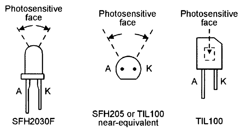
FIGURE 15. Case outline and IR-sensitive face positions of three popular types of IR photodiode.
The output of the Figure 14 pre-amplifier can be taken from IC2 and fed directly to a suitable code-waveform detector circuit, such as that shown in Figure 16. Note, however, that if the IR Tx-Rx light-beam system is to be used over ranges less than two meters or so, the pre-amp output can be taken directly from IC1, and all the RV1 and IC2 circuitry can be omitted from the pre-amp design.
A CODE WAVEFORM DETECTOR
In the Figure 16 code waveform detector circuit, the 20KHz tone waveforms (from the pre-amp output) are converted into DC via D1-D2-C2-R5-C3 and fed (via R6) to the non-inverting input of the 3140 op-amp voltage comparator, which has its inverting input connected to a thermally-stable 1V0 DC reference point.

FIGURE 16. Code-waveform detector circuit.
The overall circuit action is such that the op-amp output is high (near the positive supply rail voltage) when a 20KHz tone input signal is present, and is low (at near-zero volts) when a tone input signal is absent. If the input signal is derived from a tone-burst system, the output follows the pulse-modulation envelope of the original transmitter signal.

FIGURE 17. Expander/output driver circuit.
The detector output can be made to activate a relay in the absence of a beam signal by using the expander/output driver circuit of Figure 17.
AN EXPANDER/OUTPUT DRIVER
The operating theory of the Figure 17 circuit is fairly simple. When the input signal from the detector circuit switches high, C1 charges rapidly via D1, but when the input switches low, C1 discharges slowly via R1 and RV1; C1 thus provides a DC output voltage that is a ‘time-expanded’ version (with expansion presettable via RV1) of the DC input voltage.
This DC output voltage is buffered and inverted via IC1a, and used to activate relay RLA via Q1 and an AND gate made from IC1b and IC1c.
Normally, the other (pin 2) input of this AND gate is biased high via R2, and the circuit action is such that (when used in a complete IR light-beam system) the relay is off when the beam is present, but is driven on when the beam is absent for more than 100mS or so. This action does not occur, however, when pin 2 of the AND gate is pulled low; under this condition the relay is effectively disabled.
The R2-C2 network’s purpose is to disable the relay network via the AND gate (in the way just described) for several seconds after power is initially connected to the circuit or after DISABLE switch S1 is briefly operated, thus enabling the owner or other authorized persons to pass through the beam without activating the relay.
Note that the relay can be made self-latching — if required — by wiring normally-open relay contacts RLA/2 between Q1 emitter and collector, as shown dotted in Figure 17.
IR LIGHT-BEAM SYSTEM RANGES
The circuits of Figures 14, 16, and 17 can be directly interconnected to make a complete IR light-beam receiver that can respond to either tone-burst or continuous-tone signals; the receiver must be powered from a well-regulated 12V DC supply unit, such as that shown in Figure 18.
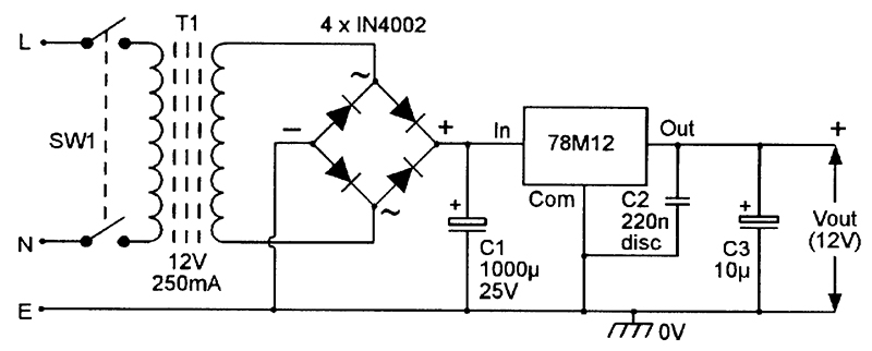
FIGURE 18. Line-powered regulated 12V, 250mA supply.
The practical maximum operating range of a complete IR light-beam security system of this type is greatly affected by the types of lenses used in the system. If additional lenses are not used, but the Tx and Rx are carefully aimed at each other, and the Rx diodes are screened from the effects of visible light by mounting them deep inside aimed tubing, the maximum range should be at least five meters, and may be as high as seven meters.
This range can be vastly increased with the help of additional focusing lenses and/or reflectors.
At the Tx end of the system, most of the optical output power of each IR LED is typically radiated over an arc of about 60°, and thus has a fairly low radiation density value. The Tx signal’s radiation density value can easily be increased by a factor of four (thus doubling the system’s effective range) by mounting each IR LED at the focal point of a simple torch-type optical reflector that is aimed at the receiver unit.
At the Rx end of the light-beam system, each IR photodiode has an integral lens that focuses the received IR light on to the diode’s photosensitive area.
On 5mm detectors such as the SFH2030F, this lens has a collection area of about 19.6mm2; in this example, the detector’s effective sensitivity can be increased by a factor of four (thus doubling the system’s range) with the help of an external 10mm2 focusing lens, or by a factor of 36 (thus increasing the range by a factor of six) with the help of a 30mm2 focusing lens.
Thus, if reasonable care is taken in the opto-mechanical design of the IR system, its range can easily be increased to 20 meters, and possibly to 60 meters or more.
PIR MOVEMENT-DETECTING SYSTEMS
IR light-beam alarms are ‘active’ IR units that react to an artificially-generated source of IR radiation. Passive IR (PIR) alarms, on the other hand, react to naturally-generated IR radiation such as the heat-generated IR energy radiated by the human body, and are widely used in modern security systems.
Most PIR security systems are designed to activate an alarm or floodlight, or open a door or activate some other mechanism, when a human or other large warm-blooded animal moves about within the sensing range of a PIR detector unit, and use a pyroelectric IR detector of the type shown in Figure 19 as their basic IR-sensing element.

FIGURE 19. Basic PIR detector usage circuit.
The basic Figure 19 pyroelectric IR detector relies on the fact that some special ceramics generate electrical charges when subjected to thermal variations or uneven heating.
Modern pyroelectric IR detectors such as the popular PIS201S and E600STO types incorporate two small opposite-polarity series-connected ceramic elements of this type, with their combined output buffered via a JFET source-follower, and have the IR input signals focused onto the ceramic elements by a simple filtering lens, as shown in the basic PIR detector usage circuit of Figure 19.
It is important to note at this point that the detector’s final output voltage is proportional to the difference between the output voltages of the two ceramic elements.
The basic action of the Figure 19 PIR detector is such that, when a human body is within the visual field of the pyroelectric elements, part of that body’s radiated IR energy falls on the surfaces of the elements and is converted into small, but detectable, variation in surface temperature and corresponding variation in the output voltage of each element.
If the human body (or other source of IR radiation) is stationary in front of the detector’s lens under this condition, the two elements generate identical output voltages and the unit’s final ‘difference’ output is thus zero. But, if the body is moving while in front of the lens, the two elements generate different output voltages and the unit produces a varying output voltage.
Thus, when the PIR unit is wired as shown in the Figure 19 basic usage circuit, this movement-inspired voltage variation is made externally available via the buffering JFET and DC-blocking capacitor C1 and can, when suitably amplified and filtered, be used to activate an alarm or other mechanism when a human body movement is detected.
In practice, pyroelectric IR detectors of the simple type just described have — because of the small size (usually about 20mm2) and simple design of the detector’s IR-gathering lens — maximum useful detection ranges of roughly one meter.
In modern commercial PIR movement detecting security units, however, this range is greatly extended (usually to well over 10 meters) with the aid of a large (about 2000mm2) multi-faceted external IR-gathering/focusing plastic lens, which splits the visual field into a number of parallel strips and focuses them onto the two sensing areas of the PIR unit.
Figure 20 shows the typical PIR sensing pattern of a commercial ‘intrusion detector’ unit designed to protect a normal-sized room in domestic-type applications. In this example, the unit is mounted on a wall at a height of seven feet and is aimed downwards at a shallow angle, and the multi-faceted plastic lens splits the visual field into a large number of vertical and horizontal segments.
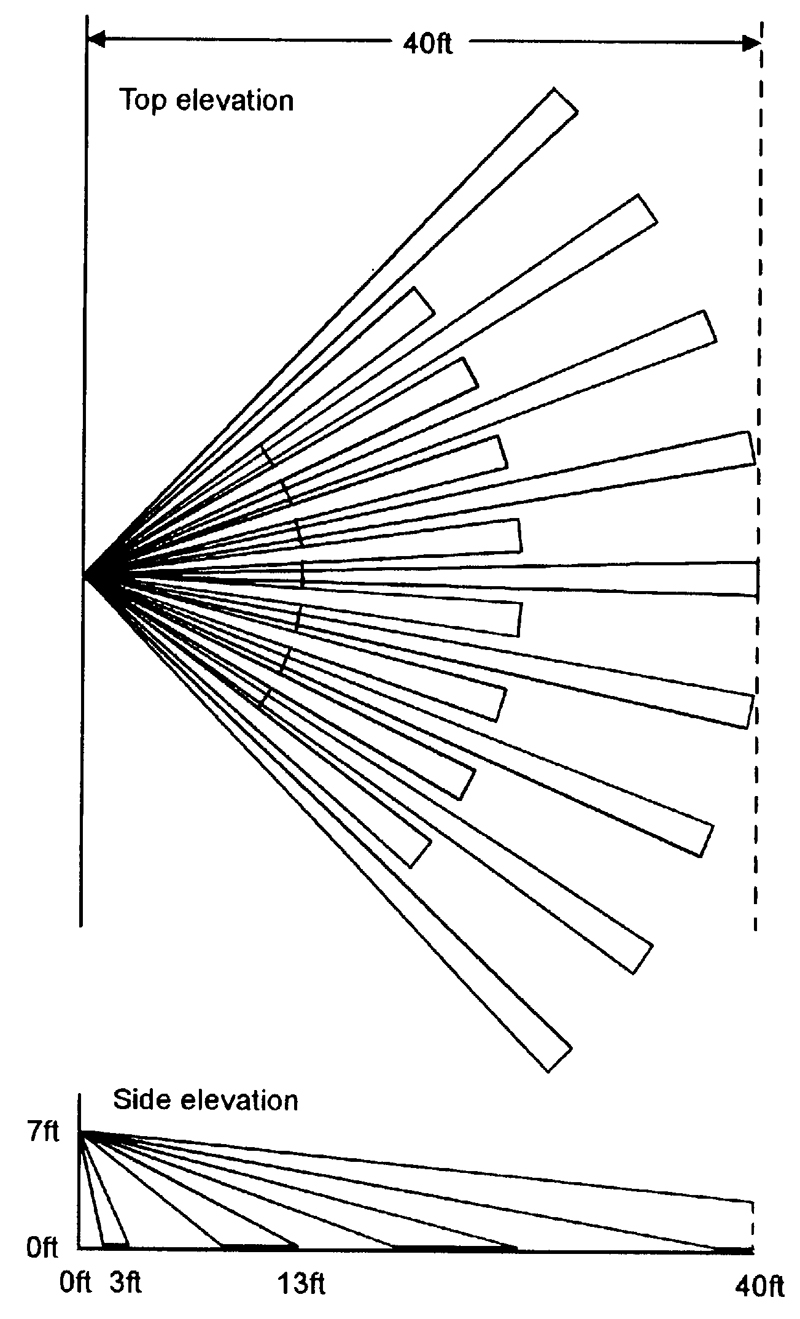
FIGURE 20. Typical PIR sensing pattern of a commercial ‘intrusion detector’ unit designed for normal domestic-type applications.
Any person moving through a single segment will activate a single trigger signal within the PIR sensor; a person moving through the entire visual field will thus produce numerous triggering signals, but a stationary IR source will produce no signals.
Most intrusion detectors of this type incorporate ‘event counting’ circuitry that will only generate an alarm-activating output if three or more trigger signal are detected within a few seconds, thus minimizing the chances of a false alarm due to sudden changes in temperature caused by the auto-activation of time-switched security lights, etc.
The lens-generated PIR sensor pattern shown in Figure 20 is the type that is often used in burglar-alarm systems to protect a single room in a medium-sized house. Alternative (and usually interchangable) plastic lens types, offering different ranges and coverage patterns for various special types of application, are available at low cost from many commercial PIR-unit suppliers.
Among the most important of these are the ‘pet’ type, in which the field’s vertical span is restricted to 2.5 to 6.6 feet above ground level to avoid activation by domestic pets while giving good sensitivity to normal humans, and the ‘corridor’ type, in which the field’s horizontal span is restricted to about 20° to give long-distance coverage (typically about 30 meters) of narrow corridors and passageways.
Note that, because high-quality commercial PIR security units of this basic type are widely available at comparatively low cost, it is not practicable (on aesthetic and economic grounds) to try to build similar units on a DIY basis. NV

