Even though microcontrollers seem pretty magical, when it comes to computations they’re really just simpletons (if fast). Most can only handle basic integer arithmetic, and only over a fairly limited range of numbers. What’s needed is a “coprocessor” onto which we can offload any serious mathematical work. Would you believe such a contrivance is often available at garage sales?
In this article, we’ll explore how to connect a typical microcontroller to the TI-83 Plus graphing calculator. It’s not really a coprocessor in the usual sense, but rather an auxiliary outboard device the microcontroller can call upon for help when the numbers get nasty.
The TI-83 Plus — by some accounts — is the biggest seller in the Texas Instruments lineup. For better or for worse, just about every middle school or high school student owns one. As a consequence, it frequently shows up at flea markets, rummage sales, and second-hand resellers on the Internet. Even if the unit has a damaged keyboard or LCD screen, it is still usable in this super-cool project.
If you’re not familiar with the TI-83 Plus graphing calculator, let me mention that it easily handles 14-digit floating point calculations, roots, exponentials, logarithms, trigonometric functions — even matrix algebra, complex numbers, and numerical calculus. All of these features become instantly available to your microcontroller projects. But there’s more ...
Data logging is a piece of cake — thanks to the large memory of the calculator — and the data can be stored in vector or matrix form for further manipulations. If statistical analysis is up your alley, then look for the seven different probability distributions within the calculator. Maybe the most intriguing application of all is direct manipulation of the calculator’s LCD screen by pixel or by character for meaningful visual displays.
If this all sounds inviting, then let’s tuck in and see how to make a microcontroller and the TI-83 Plus talk nicely to each other.
The Connections
Here’s some welcome news. It’s not necessary to hack into the calculator or modify it in any way to take advantage of what it has to offer. The TI-83 Plus already sports a jack allowing us communication access. (The manufacturer intended this for downloading software, but we’ll use it for much more.)
This port is a two-wire affair governed by a somewhat unusual hardware protocol to be explained in just a moment. But first, let jump in with both feet and see what’s going on electrically.
Figure 1 is the schematic for a test circuit which will hold you in good stead for many explorations. I went with the common and inexpensive PIC16F88, but I see no reason why what follows here wouldn’t work with just about any microcontroller sporting configurable bidirectional port lines.
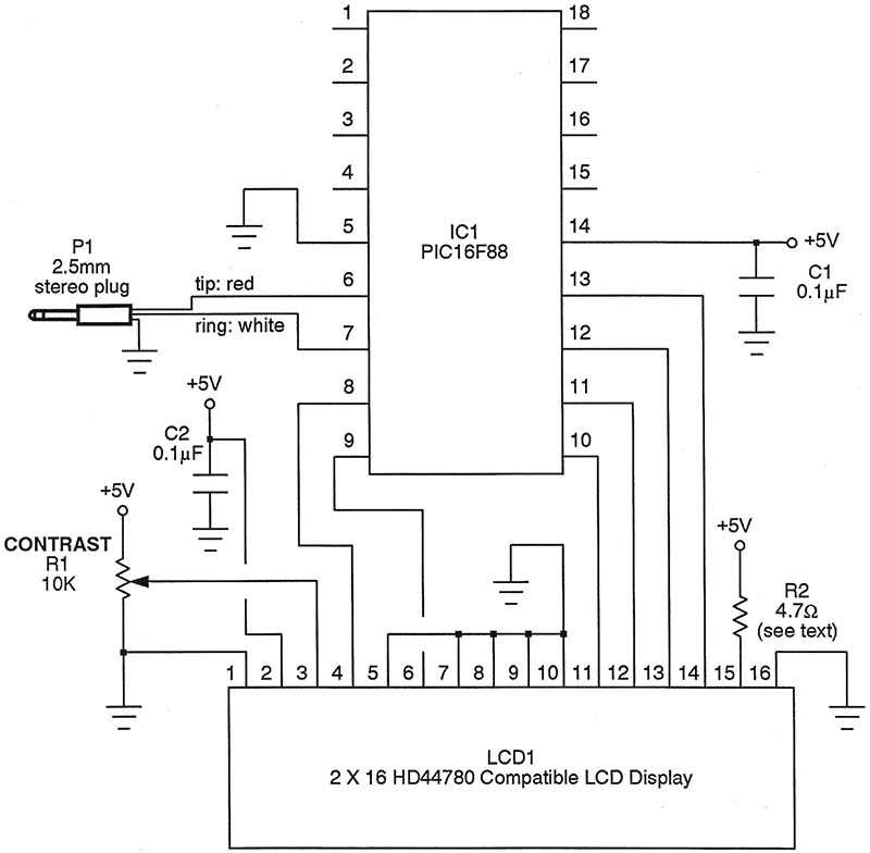
FIGURE 1.
The plug which connects to the TI-83 Plus is a small 2.5 mm stereo mini-phone type. Actually, the calculator comes with a patch cord terminated by a pair of these. Since it’s not really needed for much of anything else with only one calculator, I cut the cable in two and used one piece to make the PIC connection. If you do likewise, you’ll note that the red wire in the cable connects to the tip, while the white wire connects to the ring. Ground, of course, is provided by the braided shield in the cable.
So, the tip connects to port line B.0 (pin 6), while the ring goes to B.1 (pin 7) of the PIC16F88. Observe how uncomplicated everything is. This is a direct connection and no additional circuitry is called for!
Just so we can see what’s going on, let’s also attach an LCD to the PIC as shown in the schematic. There’s nothing new or unusual here, as this is the typical way to connect an LCD for four-bit operation. You’ll note R2 which is the current-limiting resistor for the LED backlight of the LCD. Just use whatever value is specified in your unit’s datasheet.
Well, that was pretty painless. If you’ve got it all breadboarded as shown in Figure 2, let’s see how to make the bits flow unabated between the PIC and the TI-83 Plus calculator.
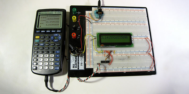
FIGURE 2.
Low Level Communication
Since only two wires are used to communicate between the devices, you might guess there’s some fancy footwork involved ... you’d be right. The data transmission is bidirectional; the PIC sends a computation to the calculator, which then returns the result amidst a flurry
of handshaking. Plus, everything must happen asynchronously. That’s a lot to ask of two wires, but it all works out quite handily. In what follows, we’ll call these lines Data0 and Data1.
During quiescence, the data direction of Data0 and Data1 are both set to input mode and will idle in a high state — thanks to the electronics of the calculator. To send a zero from the PIC, make Data0 an output line and bring it low. Now, the PIC waits for the calculator to acknowledge this with a Data1 low response.
While it might sound a bit chatty and redundant, the PIC turns right around and acknowledges the acknowledgment by bringing Data0 high again. If the calculator is happy with this state of affairs, Data1 goes high in return. We’re back where we started with both lines idling high as inputs.
To transmit a one from the PIC to the TI-83 Plus, mimic these steps but just reverse the roles of Data0 and Data1. To recapitulate, then, Data0 always transmits a zero while Data1 always transmits a one, with the alternate port line covering the hardware handshaking. Yes, it seems a trifle convoluted at first but the choreography is actually fairly straightforward and reliable.
To receive a zero from the calculator, just follow these next steps. As usual, Data0 and Data1 are idling as inputs and in a high state. When the TI-83 Plus is ready to send a zero, it will bring Data0 low. This alerts the PIC to make Data1 an output which it sets low as an acknowledgment. The calculator responds by making Data0 high again. Finally, when the PIC is content with how things have gone, it sets Data1 as an input. Once more, both port lines are idling in a high input condition. Receiving a one is very similar, with the roles of Data0 and Data1 reversed.
So, we know how to transmit and receive a single bit between the PIC16F88 and the TI-83 Plus calculator. All that’s required now is a pair of software routines to bag up everything and allow entire eight-bit bytes to be communicated. To save you the travail involved in that task, I’ve written a collection of library routines which takes care of all of the messiness for you. You can get it (called TI-LIBRARY.GCB) in the download files for this article.
For now, take a moment to spy the two low level routines of interest: GETBYTE and SENDBYTE. These superintend the details for you. Just pass in or receive byte parameters and away you go. The source code (written for the free Great Cow Basic compiler) has been heavily commented, so understanding how it all works is straightforward. Remember, the syntax of Great Cow Basic is very similar to commercial compilers or, for that matter, the interpreted Basic of the PICAXE line of microcontrollers. Porting it to some other chip shouldn’t be much of a botheration at all.
Time For A Test
We really should pause to test the essential send and receive functions before moving on to the more complicated business of transmitting entire commands. So, compile and burn the demonstration program DEMO1.GCB into a PIC16F88. You’ll note that this program leans upon the library routines just mentioned. Then, wire up the circuit shown in Figure 1 and plug it into the TI-83 Plus calculator. For this simple test, we don’t really need the LCD, so you can leave that portion off if desired.
Here’s the plan. The calculator will be running terminal software. When you press a key on it — say the letter A — that will be transmitted to the PIC, which then turns right around and sends it back to the TI-83 Plus. You’ll see the results on the calculator’s LCD screen. So, it’s really nothing more than a send-and-echo business, but will give you confidence that the one-byte character communication is working well in both directions. (See the sidebar for information on free terminal software for the TI-83 Plus which is great for this experiment.)
If everything has worked out for you, then we’re finally ready to start sending complete commands and make that calculator obey our every wish.
High Level Communication
So, we now know how to send and receive single bytes. Strings of these are assembled to create entire message packets which convey values, variables, commands, and results. This is done by means of a rather complex language called the TI Link Protocol.
Consider that your calculator has dozens of menus and hundreds of commands within it, and you’ll appreciate why the TI Link Protocol is so extensive. In a nutshell, every single feature of the TI-83 Plus is accessible via remote control now, so the associated language must necessarily be quite large. Fortunately, you really only need to know a handful of commands to get started having fun.
I gather that the TI Link Protocol was originally intended to be a proprietary, in-house affair. However, several enterprising sleuths put in a huge amount of work experimenting, observing consequences, collecting results, and writing them up in a final document available now to the general public. Entitled the Link Protocol Guide v1.4, the primary authors are Tim Singer and Romain Liévin. You’ll find it available for free download at www.ticalc.org/archives/files/fileinfo/247/24750.html. This really is a massive treatment explaining the ins and outs of the language very well. I’ll focus on a few of the commands needed to employ the TI-83 Plus as a mathematics engine with the PIC, but be sure to pour over the complete document to get even more ideas for some real microcontroller voodoo.
Let’s begin with what’s known as “silent mode remote control.” All of the actions your calculator normally carries out by means of keystrokes or menu selections can also be initiated with the cable connection detailed previously.
A desired command is formatted as a packet made up of several bytes. Let’s say we wanted to cause floating point division to occur. The packet would consist of 0x23, 0x87, 0x00, and 0x83 — four bytes total. (Transmit the individual bytes using the SENDBYTE routine described above). The first (0x23) tells the TI-83 Plus that an external microprocessor is originating the packet, while the second byte indicates that a command is coming in; not a number, variable name, or some other entity. The last two bytes — which really form a 16-bit word — signify that the PIC is requesting a division. This is followed up with a bit of software handshaking from the calculator, confirming the command was received properly.
To make this painless, the library I’ve written contains a routine called SENDCMD which accepts the 16-bit word representing the requested action and packages it appropriately for calculator consumption. You’ll find a list of all the possible actions and their ID numbers in the TI Link Protocol Guide mentioned earlier.
So, what about variables and values? Well, the TI-83 Plus expects numbers to always be in a specific format. For example, the quantity that we would ordinarily write as 123.4567 is represented within the calculator as:
0x00, 0x82, 0x12, 0x34, 0x56, 0x70, 0x00, 0x00, 0x00
Do you see the pattern? The first byte gives the sign 0x00 for non-negative numbers, and 0x80 for negatives. The second specifies the exponent of the power of 10 if we’re to write the number in scientific format, but normalized to 0x80. Thus, 0x80 means an exponent of 0, 0x81 is for 1, and so on up to 0xE9 for an exponent of 99 — the largest you can go. On the other hand, 0x7F would signify an exponent of –1, 0x7E would be –2, on down to 0x1D which means –99.
The remaining bytes are the packed binary coded decimals (BCDs) of the mantissa; 14 digits in all. The implied decimal point is between the first and second digit.
This is a great system for the calculator, but not necessarily for humans. But again, the library comes to our rescue. I thought it would be pleasant to be able to read and write numbers in everyday decimal fashion and as ordinary strings. (Yes, unlike many other Basic compilers, Great Cow Basic handles strings and does so very elegantly.) So, for the above example, you could simply specify the string “123.4567” in your PIC code and the library routines will automatically take care of massaging that into the form required by the TI-83 Plus.
As for loading and reading variables, look for the subroutines called SENDNUM and GETNUM in the software library for this article. To stuff a value into a variable, simply set the global variable NAME equal to the ASCII value of the name (0x41 for A, 0x42 for B, and so on), and set the global string variable called VALUE to the desired decimal number. Then, invoke SENDNUM and lo and behold! Your calculator has that variable and value all set to go.
The subroutine takes care of packing the BCDs, setting exponents, etc., as well as the extensive handshaking and checksum business required. It’s all very easy to do now. GETNUM works in a similar way to retrieve a value from the TI-83 Plus, managing the software handshaking, unpacking the number to a string, and so on. Keep in mind that you’ll be able to manipulate not only integers, but floating point numbers spanning –9E99 to –9E99, and with up to 14 digits of precision. The PIC has become a mathematical savant now!
The Big Demonstration
So, we’ve met the required subroutines now:
SENDBYTE
GETBYTE
SENDCMD
SENDNUM
GETNUM
Let’s see what they can do. If you haven’t already beaten me to the punch, compile the DEMO2.GCB source code and burn it to the PIC16F88. (Or port the code over to your microcontroller of choice).
Here’s what you’ll witness when you fire up the circuit: 456.78 will be divided by 30123.456 (not the sort of thing you do every day on an integer based microcontroller), and the result of 0.01516359875838 is displayed on the PIC’s LCD. Then, the square root of 456.78 is computed and exhibited. Next, a 14-digit approximation to the constant PI is displayed. The demonstration concludes by drawing a circle on the calculator LCD — all under PIC control.
Final Calculations
If you’re used to being hamstrung by word-based integer arithmetic, then even this simple demonstration program seems pretty incredible. If you’re not so easily impressed, however, remember we’ve only scratched the surface.
With the hardware and firmware described here — along with the encyclopedic TI Link Protocol Guide — a whole new world of trigonometry, exponentials, logarithms, complex numbers, statistics, matrix algebra, and more awaits you!
Now, go figure it out! NV
A Preliminary Test
Getting a calculator to communicate with a PIC is a moderately complex business with plenty of opportunities for things to act up. When they do, it can be difficult to determine whether it’s the hardware or software that’s at fault. For that reason, I began this project with several simple experiments just to convince myself I understood what was going on. Here’s a great first test to give you confidence you’re nailing the basics down.
In this experiment, we’ll simply tie the TI-83 Plus calculator and a PC together, and confirm that they can send data back and forth. Both devices will be running terminal software and so will be talking ASCII to each other. Press a key on the calculator and it’ll be reflected on the PC. Then, press a key on the PC and look for it to be echoed to the TI-83 Plus.
The connection is by means of the commercial TI-Graph Link serial gray cable. This is manufactured by Texas Instruments and available for about $15 from Amazon and other dealers. Attach the mini-phone plug to the calculator. On the other end, connect the DB-9 plug to an RS-232 COM port on your PC. If you don’t have such a fitting, there are lots of inexpensive USB-to-COM adapters kicking around. Again, Amazon is a good source.
Now, you need to load up some terminal software on both the TI-83 Plus and the PC. Let’s focus on the calculator first. Rather unbelievably, there exists a very nice and free terminal program for the TI-83 Plus. In order to run it, though, you need to first load in a software shell (also free), so let’s begin there. Go to joewing.net/projects/ti83/ion and download the shell entitled ION 1.6. Just follow the easy installation instructions and you’ll be set for the next step. Incidentally, ION 1.6 was written by Joe Wingbermuehle.
Next, return to the Web and download Telnet 83 Plus SE 1.9 from www.ticalc.org/archives/files/fileinfo/178/17878.html. This is a full-featured terminal program. It really is amazing to see a handheld calculator doing things that a mere 30 years ago were only being carried out on mainframes. Again, follow the included instructions to install and use Telnet 83 Plus. The authors in this case are Justin Karneges (who did the original implementation) and Hideaki Omuro (who ported it to run under the ION 1.6 shell).
Now, let’s turn to the PC. I like using the terminal software written by Br@y++ (that’s not a misprint) and available for free download at https://sites.google.com/site/terminalbpp. There’s nothing to install here. Just run it and away you go.
Here’s an easy-to-miss necessity. The TI-Graph Link cable is powered by the RTS line on your computer. (That’s part of the RS-232 protocol). So, in the PC terminal program, be sure you’ve enabled that line. In the terminal of Br@y++ I’m using, there’s a button to let you do exactly that. Conclude by making the communication settings 9600 baud, eight data bits, one start bit, one stop bit, and no handshaking.
If you made it past all that (and it took me several days to sort it out myself), then the calculator and the PC should be talking nicely to each other. Confirm that you can send ASCII text back and forth reliably. Just this experiment alone ought to give you some ideas for future projects.
Downloads
What’s in the zip?
GCB source code files for demos and library.
