After using a 3.5 inch Nextion display for building a thermostat, I quickly envisioned using these displays with my latest version of a digital clock. The Nextion display is a leap forward in LCD touch displays. The built-in microprocessor makes building a professional looking touch display interface quite easy and takes a lot of overhead off the microprocessor connected to the display.
If you aren’t familiar with the Nextion displays, you should refer to Mike Holler’s excellent series of articles on these in previous issues of Nuts & Volts. The learning curve for these displays is a little steep and these articles are a great help. I haven’t used the Nextion library in my projects but rather have sent and received direct commands to the Nextion displays through the serial interface.
Nextion displays come in a variety of sizes with different capabilities and features. My digital clocks used the 3.5, 5, and 7 inch sizes. The 3.5 and 5 inch models used are the Nextion basic model while the seven inch is the intelligent model. The Nextion web page at https://nextion.tech describes the different models on the Products tab. All the different sizes I used run from the same circuit and printed circuit board (PCB) described in this article; only the software differs.
The 3.5 and 5 inch sizes have the same features:
- Requires a wireless Internet connection to function. Will attempt a connection using several different routers, allowing it to be moved to different locations. Attempts a read from a micro SD card with an SSID and password, allowing connection to a new router without having to reprogram the ESP32.
- Displays time from different time zones depending on what is chosen for the home location.
- Displays sunrise and sunset of the home location.
- Speaks time and temperature with screen touch.
- The various pages on the display have images for background.
- The text display colors for time, temperature, sunrise, sunset, date, and day of the week can be selected.
- Displays weather (temperature, humidity, conditions, wind) for the home location, or scans nine different locations. Weather can be turned off.
- Clock never needs to be set as time is captured every minute from the Internet. Time zone and Daylight Saving Time is automatically adjusted.
- Displays metric if desired.
- Has a picture frame function. Images are displayed nearly instantaneously every 10 seconds.
The seven inch version has additional features:
- Plots the indoor and outdoor temperature over time and displays this live on a graph. Only the Fahrenheit scale can be used.
- Reports the DOW 30 company’s stock prices, which are delayed.
- Has an alarm function.
Hardware
The main components on the PCB are:
- ESP32 Microcontroller
- DS3231 Real Time Clock (RTC)
- Four-pin Header to Connect BME280 Temperature, Humidity, and Pressure Sensor
- PAM8403 Audio Amplifier
- Four-pin Header to Connect Nextion Display
- Pads for an Optional micro SD Card Board
- Pads for an eight ohm Speaker Connection
Miscellaneous parts include: 1,000 µF 6.3 volt electrolytic capacitor, 0.1 µF capacitors (four), header pins, two- or three-pin terminal blocks (two), 5.5 x 2.1 mm jack, five volt/one amp wall wart type power supply with mating plug, various screws, nuts, wire, solder, header pins, two-pin slide on header jumper, 30 cm/four-pin header jumper, project box, and 40-pin IC socket cut in half longitudinally for the ESP32. Figure 1 shows the schematic for this project.
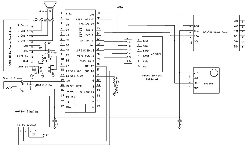
FIGURE 1. Nextion digital clock schematic.
Figure 2 shows the completed circuit on a PCB.
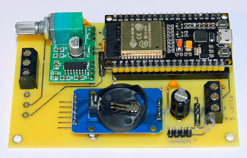
FIGURE 2. Assembled circuit on a PCB.
A PCB is a great convenience when assembling this circuit, but it’s certainly possible to use a breadboard and point-to-point wiring. An ExpressPCB layout for this circuit is included in the downloads. The Express PCB software can be downloaded from https://www.expresspcb.com. Pads are included for either 0.9 or 1.0 inch wide ESP32 development boards. The pads for connecting a micro SD card board are positioned under the ESP32, and are laid out in the correct order to match my micro SD card board.
Check to make sure the micro SD card board you use has the same pin layout. One end of a four inch/six-pin header pin jumper was cut off and the wire ends soldered into the micro SD card pads on the PCB. The optional micro SD card board can then be plugged into the opposite end.
If a micro SD card is not installed, the micro SD card board should be unplugged. Additional pads were included in this PCB design for additions or changes that are not used in the circuit described here.
A four-pin/12 inch long header jumper is used to connect the BME280 temperature, humidity, and pressure board to a four-pin header on the PCB. This keeps the temperature and humidity sensor from being heated by the PCB components. There’s a slot in the back cover of the project box that was 3D printed to bring the four-pin header jumper out.
A four-pin header is on the PCB for connecting the Nextion display. The Rx line on the Nextion display goes to the Tx (pin 17) on the ESP32 and Tx on the Nextion display to Rx (pin 16). The Nextion displays come with a wire connector that has mating connectors for header pins. The DS3231 RTC board has four pads provided at the opposite end of the board from the header pins. A four-pin header is soldered into these pins and then the long ends of the header pins are soldered into the PCB. The socket for the battery on this board should face up. The battery isn’t needed as the time is obtained from the Internet every minute.
The PAM8403 audio amplifier board needs header pins soldered into it. After these are in place, the long ends of the header pins are soldered into the PCB. Note that only the left channel of the amplifier is used. The right channel has breakout pads on the PCB for optional use. The volume potentiometer on this board has a built-in on-off switch which must be switched on.
I found a small 80 x 40 mm/eight ohm speaker on eBay and it worked well for my small project enclosure. Any small eight ohm speaker can be used and wired directly onto the PCB. The pads for the speaker were sized for miniature terminal blocks.
The Nextion Software
The procedure I used for writing software for the clock functions and communicating with the Nextion display was to first program a Nextion display page (Figure 3) using the Nextion Editor and then add code for the ESP32 in the Arduino IDE (integrated development environment) to utilize the Nextion display page.
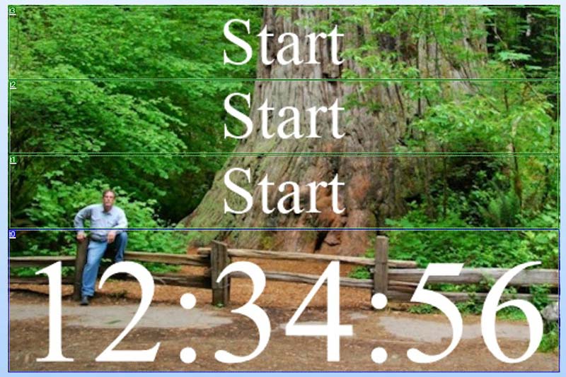
FIGURE 3. Nextion display page 0.
The Nextion Editor is available at https://nextion.tech/nextion-editor.
The first page of the Nextion display, page 0, has a background image and four textboxes numbered t0 to t3 and is laid out bottom to top. Textbox 0, t0 in the Nextion program is at the bottom of the page and was made as large as possible because it displays the current time. The three textboxes above the time are used to display the city name of the home location, date, day of the week, sunrise, sunset, and the local temperature and humidity from the BME280.
A string containing the time is sent through the serial interface to the Nextion display once per second to t0 with the following code:
// Write the time to the Nextion
tempstr = String(bhour) + “:”;
if (bminute < 10) tempstr.concat(“0”);
tempstr.concat(String(bminute));
tempstr.concat(“:”);
if (last_sec < 10) tempstr.concat(“0”);
tempstr.concat(String(last_sec));
sendThis = “page0.t0.txt=\””; // Build the part of the string that we know
sendThis.concat(tempstr); // Add the variable we want to send
sendThis.concat(“\””);
writeString(sendThis); // Use a function to write the message
// character by character to the Nextion
// because mySerial.write(sendThis) gives you
// an error due to a datatype mismatch
A string is created using the hour, minute, and second variables and is then added to the string page0.t0.txt”. The closing quote marks are added. So, what we’re sending is page0.t0.txt=”12:34:56” where in our program we use the \” to define a quote mark which is inside the quote marks that define the string. This is a standard format for sending a string to a textbox in the Nextion display.
Note that no spaces are used, and we must define what page the textbox is in, its name such as t0, the .txt qualifier, and then the string itself inside quotes. The following code sends the home location name to the textbox t3 at the top of page 0:
sendThis = “page0.t3.txt=\””;
sendThis.concat(Name);
sendThis.concat(“\””);
writeString(sendThis);
Each textbox needs a font associated with it; the font number is selected in the Attribute window in the lower right of the Nextion Editor after clicking on a specific textbox. Fonts must be created with the Font Generator (Figure 4) which is found in the Tools menu.
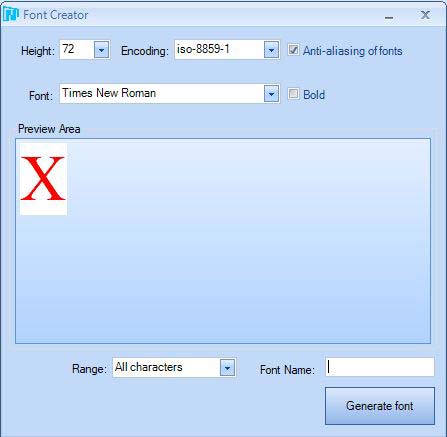
FIGURE 4. The Font Generator.
A selection is made from the list of fonts available on your computer running the Nextion Editor. Its height, or size, is also selected and there’s a checkbox for making it bold.
Lastly, a Font Name must be created before clicking Generate Font. A Save As window will then appear and again a Font Name must be chosen. Click Yes when the Add the Generated Font window comes up.
Your available fonts will appear in the Fonts window by clicking on the Fonts tab at the very bottom left of the Nextion Editor. Once fonts are created, they can be selected for any textbox on any page.
The 3.5 inch Nextion clock has the following pages:
- page 0: Displays home location, date, and day of the week from 0 to 14 seconds. Displays home location, sunrise, and sunset from 15 to 29 seconds. Jumps to page 3 to display weather details from 30 to 44 seconds. Displays local temperature and humidity from the BME280 from 45 to 59 seconds.
- page 1: This is the Menu page to allow changes in the display pages.
- page 2: This page allows selection of the home location from nine choices.
- page 3: This page is used to display weather details.
- page 4: This page acts as a photo frame when selected.
- page 5: This page allows selecting different colors for text boxes on page 0.
The Menu page (Figure 5) is accessed by touching the textbox containing the time on page 0.
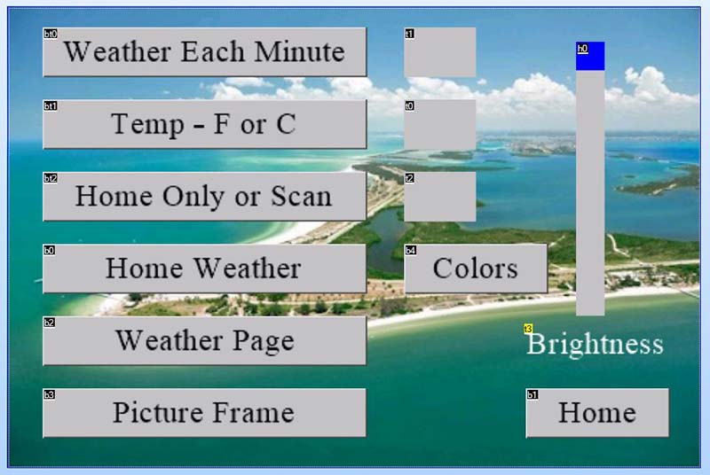
FIGURE 5. Page 1, the Menu page.
From the menu page, other pages can be accessed. Touching textbox t2 on page 0 will speak the time and some weather details.
The Menu page has three dual-state buttons at the top with small textboxes to the right of each one. These act like on-off buttons to define which state a setting is in. They jump to the weather page each minute or not, show Fahrenheit or Celsius for temperature (also changes in wind velocity), and use only the home location or scan between nine different city locations.
The state of a dual-state button is shown in the small textbox to the right. The Home Weather button jumps to page 2, where the home location can be chosen. The Weather Page button jumps to page 3, the weather page. The Picture Frame button jumps to page 4, which displays a series of images that have been added through the Nextion Editor. The Colors button jumps to page 5, where colors can be selected for the textboxes on page 0.
Lastly, there’s a brightness slider to reduce the brightness of the display which is a useful addition for people who don’t want a bright light when used in the bedroom.
Notice here that page 0 of the Nextion display was used by sending differing text to the appropriate textboxes. The use of page 1 is quite different. The dual-state buttons send a Component ID to the ESP32 microcontroller, telling it which button was pressed. This is programmed in the Nextion Editor by checking the Send Component ID box located in the Event window.
When the Component ID is received by the ESP32, the current state is echoed back as a single character to the Nextion display and shown in the small textboxes to the right of the dual-state buttons. The Component ID is received in the mySerialEvent() function and then is passed to the get_Nextion_command() function The remaining five buttons and the brightness slider are all programmed in the Nextion Editor. Their actions only affect things in the Nextion display so the ESP32 doesn’t need to deal with these actions.
Pressing the Home button jumps to page 0. To program this into the Nextion display, the Home button is selected and the Nextion command “page 0” (without the quotes) is entered in the Events window of the Nextion Editor after selecting the Touch Release Event button. For the Home Weather, Weather Page, Picture Frame, and Colors buttons, the Nextion command for the Touch Release Event is page 2, page 3, page 4, and page 5, respectively. With the Brightness slider, h0, we finally get into writing a small piece of code for the Nextion display.
After selecting the h0 slider, click on the Move Event button in the Events window. In the window below, the following was typed in:
if(h0.val>20)
{
dim=h0.val
}
As the slider is moved, the dim system variable that controls the brightness of the Nextion display is changed. The value of h0 can range from 0 to 100, but 20 was chosen as the darkest allowed. This system variable is documented in the Instruction Set page which is accessed from the Help tab of the Nextion Editor.
It should be noted here that the majority of buttons on page 1 create actions solely contained within the Nextion display itself, without intervention of the ESP32 microcontroller. This is one of the great advantages of the Nextion displays. The built-in Nextion display microcontroller can take care of many of the desired changes we want in the Nextion display.
The Home Selection page (Figure 6) is page 2 and contains nine buttons with the names of various locations where I have family.
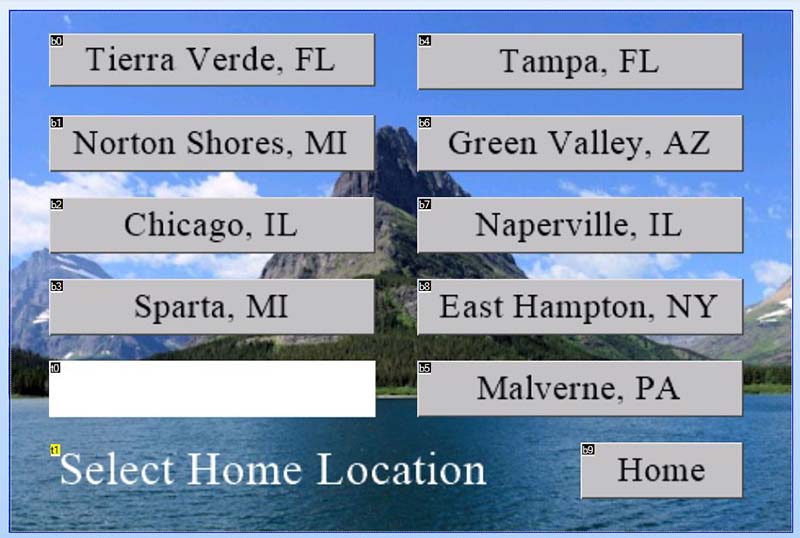
FIGURE 6. Page 2, the Home Selection page.
The ESP32 software defines a default home location but this can be changed in page 2.
When one of the buttons is pressed, the Component ID of that button is sent to the ESP32. So, what does the Component ID actually look like when sent to the ESP32? The easiest way to see this is to use the Debug tool in the Nextion Editor.
When the Tierra Verde button (Figure 7) is pressed, the following bytes are sent out the serial port to the ESP32: 0x65 0x02 0x01 0x00 0xFF 0xFF 0xFF.
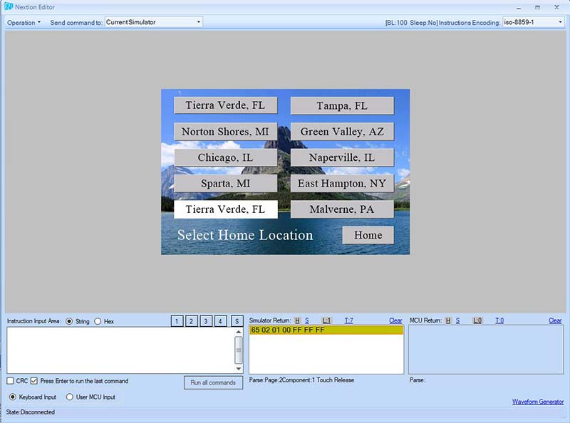
FIGURE 7. Debug simulator after the Tierra Verde, FL button is pressed.
The 0x65 designates a touch event; the 0x02 designates the page number; 0x01 is the Component ID; 0x00 is the event (0x00 is released and 0x01 is pressed), followed by the three 0xFF bytes which terminate all commands.
I often change the buttons on this page to match the interest of the person for whom the digital clock is built. Because of this, the Component IDs of the buttons are not always in order or have gaps in the numbering.
Using the Debug Tool is a convenient way to capture the appropriate list. With some components, there’s a second list of values. For example, the state of a dual-state button is sent in the second list of bytes.
Each second the program checks to see if a string of characters has been sent from the Nextion display. If so, the characters are stored in an array called bstring[] and then the get_Nextion_command() function is called.
Included in this function is a line like:
if ((bstring[0] == 0x65) && (bstring[1] == 0x02) && (bstring[2] == 0x01) && (bstring[3] == 0x00)) myHome = 0;
This if statement captures the fact that the Tierra Verde, FL button has been pressed and assigns the home location to the myHome variable.
The Weather page (Figure 8) simply contains five large textboxes to display details of the weather at the current home location.
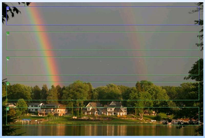
FIGURE 8. Page 3, the Weather page.
Its only function is to receive text strings: t0 receives the city name of the current home location; t1 receives a brief description of conditions; t2 receives the temperature; t3 receives the humidity; and t4 receives the wind speed and direction.
A touch on the screen between the textboxes or at the bottom will return to page 0. Note that a fairly dark image was used for the background which works well with white text.
Page 4 shown in Figure 9 contains a photo frame instead of a digital clock function.

FIGURE 9. Page 4, a photo frame.
The memory available allows over 40 pictures to be displayed. All pictures used with a 3.5 inch Nextion display (which are full frame) should measure 480 x 320 pixels.
My pictures consist of the usual family, myself at travel locations, some scenery, and a few birds. The .HMI and .TFT files created by the Nextion Editor (and available in the downloads) will contain my pictures.
To substitute your own, first resize your pictures to 480 x 320 pixels. In the Nextion Editor, pictures are imported in the lower left window. If the heading doesn’t show Picture, then click on the Picture tab at the bottom of the window. Pictures are added with the plus symbol and deleted with the minus symbol (Figure 10).
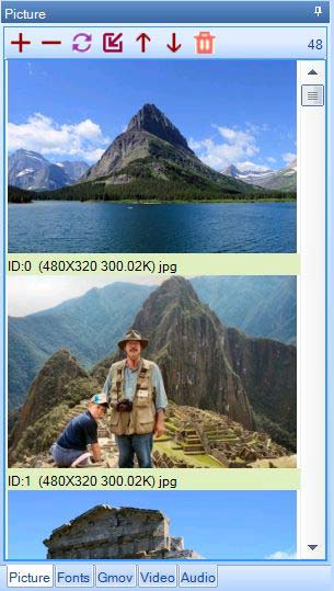
FIGURE 10. The Picture Selection window.
This page has a timer and a variable which are selected from the Toolbox at the upper left. These components will not appear on the page but do show up at the bottom of the Display page. Settings for these components are selected after you click on one and then review the Attribute window on the lower right.
For the Timer component tm0, I set the time to 10000, which is the time in milliseconds. For the variable va0, I left the default value as 0 and set the Variable type as Number. In the Timer Event window, I added the following:
va0.val=va0.val+1
if(va0.val==48)
{
va0.val=0
}
page4.pic=va0.val
Every time the Timer counts down to zero milliseconds, this code is run. The variable va0 is increased by one. Then, if the variable is 48, it’s changed to 0 (we have 48 pictures numbered 0 to 47). Lastly, the pic (picture) number on page 4 is assigned the va0 value, and the next picture will appear.
Page 5 shown in Figure 11 has two variables attached: va0 which stores the color number 0-5 for textbox0 on page 0 that displays the time every second; and va1 which stores the color number 0-5 for the remaining three textboxes on page 0.
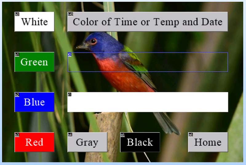
FIGURE 11. Page 5, the Select Text Color page.
The following code is entered into the Touch Release Window for b0, the white button:
if(page5.bt0.val==0)
{
page0.t0.pco=65535
va0.val=0
}else
{
page0.t1.pco=65535
page0.t2.pco=65535
page0.t3.pco=65535
va1.val=0
}
t0.pco=65535
t1.bco=65535
t1.pco=0
Similar code is assigned to each of the other five color buttons in their Touch Release Events windows. The only difference in the code will be the color numbers assigned to the text and background colors. Sixteen-bit color numbers are used: five bits for red; six bits for green; and five bits for blue.
After the if statement, the textboxes on page 5 are also assigned the white color to demonstrate its appearance. The dual-state button bt0 has additional code. If the dual-state button is in state 0 (not pressed), the color buttons will assign color to the t0 time textbox on page 0.
If pressed, the color will be assigned to the other three textboxes on page 0:
if(bt0.val==0) // Time
{
t0.txt=”Time 12:34:56”
t1.txt=”Select Color for Time”
if(va0.val==0)
{
t0.pco=65535
t1.bco=65535
t1.pco=0
}
if(va0.val==1)
{
t0.pco=1024
t1.bco=1024
t1.pco=65535
}
if(va0.val==2)
{
t0.pco=31
t1.bco=31
t1.pco=65535
}
if(va0.val==3)
{
t0.pco=63488
t1.bco=63488
t1.pco=65535
}
if(va0.val==4)
{
t0.pco=50712
t1.bco=50712
t1.pco=0
}
if(va0.val==5)
{
t0.pco=0
t1.bco=0
t1.pco=65535
}
}
if(bt0.val==1)
{
t0.txt=”Temp and Date”
t1.txt=”Select Color for Temp and Date”
if(va1.val==0)
{
t0.pco=65535
t1.bco=65535
t1.pco=0
}
if(va1.val==1)
{
t0.pco=1024
t1.bco=1024
t1.pco=65535
}
if(va1.val==2)
{
t0.pco=31
t1.bco=31
t1.pco=65535
}
if(va1.val==3)
{
t0.pco=63488
t1.bco=63488
t1.pco=65535
}
if(va1.val==4)
{
t0.pco=50712
t1.bco=50712
t1.pco=0
}
if(va1.val==5)
{
t0.pco=0
t1.bco=0
t1.pco=65535
}
}
It should be noted here that all this code is handled by the Nextion microcontroller, so the ESP32 doesn’t have to use any of its processing time to deal with these colors.
The ESP32 Software
Figure 12 is a basic flowchart of the ESP32 software and is a typical loop structure that checks things as follows:
- At 0 seconds, it gets time from the Internet, stores it, and writes it to the DS3231.
- At 15 seconds, it calculates and writes sunrise and sunset to page 0.
- At 30 seconds, it jumps to page 3 and displays the weather.
- At 45 seconds, it reads the BME280 and writes local temperature and humidity to page 0.
- At 50 seconds, it reads the weather from the Internet and stores the results.
- Every second, it checks if Wi-Fi is connected, then checks if a Nextion command has been received.
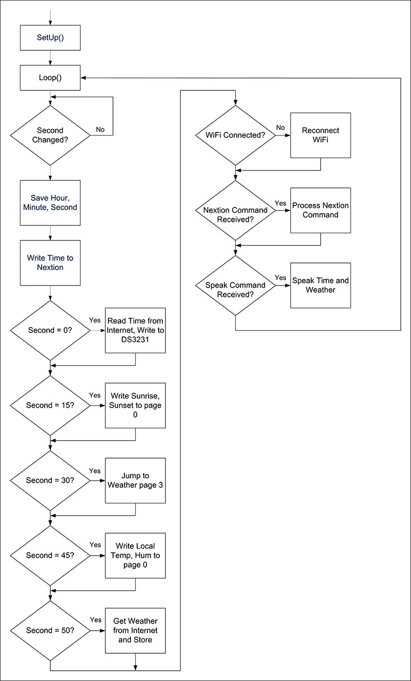
FIGURE 12. Basic flowchart of ESP32 software.
The Network Time Protocol servers at pool.ntp.org are used to retrieve the time from the Internet. Details on this service are available at https://www.ntp.org. The weather is retrieved from the open Weather API. Details on this service can be found at https://openweathermap.org/api.
Along with this service, you’ll need the city IDs to tell the Weather API which city weather you’re requesting.
The city lists containing the city IDs can be found at http://bulk.openweathermap.org/sample/. These lists are in .gz compressed format. After you decompress a list, use a program like 7-Zip where you can search for a city name. Be sure to check the latitude and longitude coordinates as many cities have the same name.
The major functions in the ESP32 program are:
- bool WiFi_Connect() - Connects to an Internet router with Wi-Fi using up to seven different SSIDs and passwords. If the wireless router doesn’t respond after 20 seconds, it checks using the next SSID and password.
- void mySerialEvent() - Checks the Serial2 port on the ESP32 for a command coming from the Nextion display.
- void get_Nextion_command() - Parses the commands received from the Nextion display and takes the appropriate action.
- void do_weather() which calls int getWeatherFromInternet (String location, String isitHome) which calls String parse_it(String tag, String isitHome) - Retrieves the weather information for a specific location, saves it, and sends it to page 3, the Weather page.
- void speak() which calls void talk_time() and void parse_Desc(String d) void talk_time() calls void say_less_20(int num) and void say_tens(int t) - Speaks the time and some weather information.
- void check_for_sd_card() - Checks for a micro SD card through the SPI interface and if found, looks for a file named “internet.txt” and then reads it for an SSID and password, which is used for the Internet connection.
- String timeStamp(long ts, bool full, long offset) - Reads the Unix timestamp to recover the current sunrise and sunset times.
The entire digital clock program can be found in the downloads.
Talkie Software
I use an ESP32 version of the Talkie software to implement the speaking feature of my software. Talkie is a unique piece of software that uses the linear predictive coding algorithms used in the Texas Instruments Speak and Spell toys from the 1970s. This software can be found at https://github.com/bobh/ESP32Talkie.
You’re limited to a small group of words, but there are just enough to implement speaking the time and some weather. Each word is contained in a lengthy constant byte array. So, to save memory, I’ve only included the words needed.
The output from this software is placed on pin 25 of the ESP32, then this pin is fed into one channel of the PAM8403 audio amplifier through a 0.1 µF capacitor with a 1K resistor on the input tied to ground to reduce noise.
The Seven Inch Nextion Digital Clock
While I have made a digital clock using the five inch Nextion display, it’s basically the same as the 3.5 inch model but using the larger display.
The seven inch Nextion display I purchased was from the Intelligent series, which has additional features. The seven inch displays are 800 x 480 pixels in size.
The Menu page for the seven inch model is shown in Figure 13 and reflects its additional features.
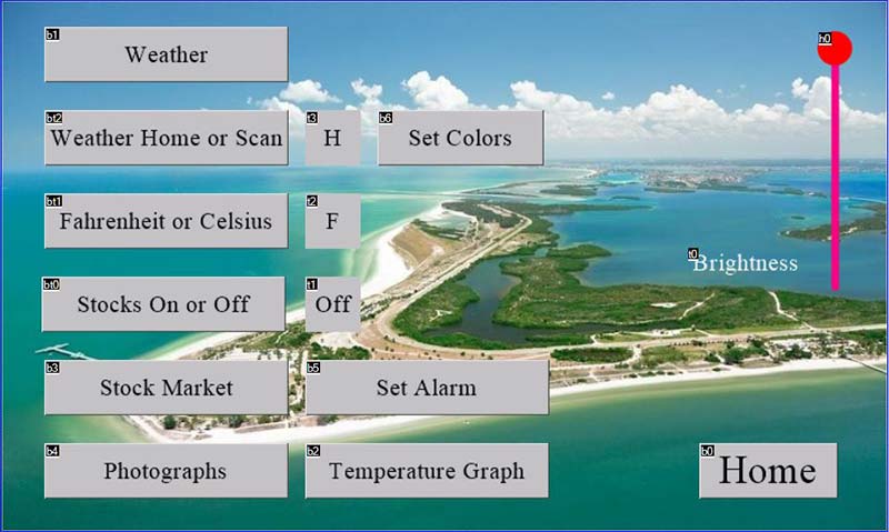
FIGURE 13. The Menu page for the seven inch Nextion digital clock.
There are buttons for the stock market display, an alarm, and temperature graph.
The Waveform component was used to graph the indoor and outdoor temperatures over the course of a day, reading these values every two minutes.
The layout of the Temperature Graph page is shown in Figure 14.
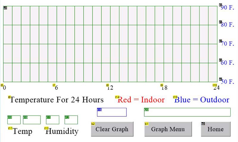
FIGURE 14. The Temperature Graph page with a Waveform component.
The Waveform component is sized to 722 x 258 pixels allowing for one pixel borders. A reading of the temperatures is done every two minutes; therefore, there are 720 points to be plotted each day.
The temperature value needs to be normalized to range between 0 and 255, based on the scale chosen. The default scale is 50-90 degrees Fahrenheit. A point is plotted on the Waveform component with the following statements:
sendThis = “add 1,0,”;
sendThis.concat(String(temp_graph));
writeString(sendThis);
The string “add 1,0,201” will add a point 201 pixels high to Waveform component 1, channel 0. The temp_graph variable contains the normalized value of the temperature. The temperature range of the graph can be changed using the Graph Menu page, and this change needs to be reflected in the temp_graph values when computed. The 40 degree spread works well for most locations.
The Graph Menu page is shown in Figure 15
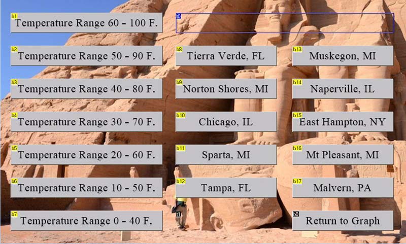
FIGURE 15. The Graph Menu page.
This page allows a change in the temperature range as well as selecting the home location.
Adding stock market quotes adds a new layer of complexity. Stock quotes are obtained from the IEX Cloud API. See https://iexcloud.io/docs/api for details. I chose the DOW 30 list of companies for the stock prices I wanted to display. The Stock Market page (page 5) is very similar to the Weather page and contains five scrolling textboxes and one regular textbox.
Because there are a lot of Internet requests to obtain stock quotes, the second core of the ESP32 is set up to continually request stock quotes when the stock market feature is turned on.
Each minute, five of the 30 DOW stocks will be displayed, with the next five the following minute until all 30 are displayed.
To delegate this task to the second core of the ESP32, a Taskhandle is created at the top of the program after the #define statements:
TaskHandle_t Task0;
Then, in the setup() function, we create a structure to pin a task to a specific core in the ESP32:
xTaskCreatePinnedToCore(
Task0code, // Function to implement the task
“Task0”, // Name of the task
7000, // Stack size in words
NULL, // Task input parameter
1, // Priority of the task
&Task0, // Task handle
0); // Core where the task should run
The Task0code(void * parameter) function is then created and placed after the loop() function:
// Read stock prices using second CPU
void Task0code(void * parameter)
{
// Task here must never end or return
String tstring;
while(true)
{
if (stock_on)
{
// Get stock quotes from Internet
for (int j = 0; j < 30; j++)
{
for (int i = 0; i < 5; i++)
{
stock_temp[j] = getStocksFromInternet(stock_sym[j]);
if (!(stock_temp[j].indexOf(“,,”) > 0))
{
break;
}
delay(200);
}
tstring = parse_stock(stock_temp[j], stock_sym[j]);
}
if (debug_min)
{
Serial.print(“the_stock = “);
Serial.println(String(the_stock));
}
if (the_stock == 30)
{
dow = total_price / 0.14748071991788; // This value must be kept current for DOW
sendThis = “page5.t0.txt=\””;
sendThis.concat(“DOW Ind. “);
sendThis.concat(String(dow));
sendThis.concat(“ “);
sendThis.concat(xtempstr);
sendThis.concat(“\””);
writeString(sendThis);
if (debug_min)
{
Serial.print(“DOW = “);
Serial.println(sendThis);
}
}
the_stock = 0;
total_price = 0.0;
delay(500);
}
}
}
There’s a built-in alarm function which uses the speaking feature when the alarm goes off. On the Alarm Menu page (Figure 16), AM/PM is selected and then the time is entered using the keypad.
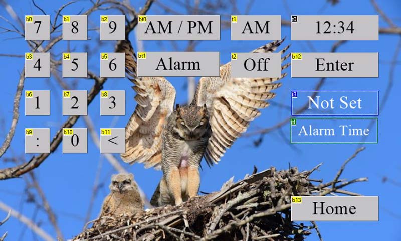
FIGURE 16. The Set Alarm Menu page.
The time is stored after pressing the Enter key. The alarm function is turned on or off with the Alarm button.
The Text Color Selection menu shown in Figure 17 is similar to that of the 3.5 inch Nextion digital clock.
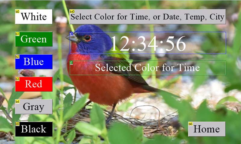
FIGURE 17. The Text Color Selection menu.
Conclusion
Digital clocks made with Nextion displays are a great design. The hardware needed is reduced compared with an LED display, which requires either hardware drivers like TTL 7447s or a scanning structure that creates overhead for the microcontroller.
The Nextion display provides numerous components that enhance the appearance of the display and images are available for backgrounds or use with components.
Because of the sophistication of the display, the amount of software that needs to be written to exploit this increases. The pages that appear in the display itself must be programmed with the Nextion Editor. The attached microcontroller also needs additional code to exploit the Nextion display
There are blocks of code to deal with Internet access including reading the time, weather, stock prices, or other data from the Internet. Features like plotting a temperature graph add to the complexity.
The end result (Figure 18) is a display that is much more attractive and informative. NV
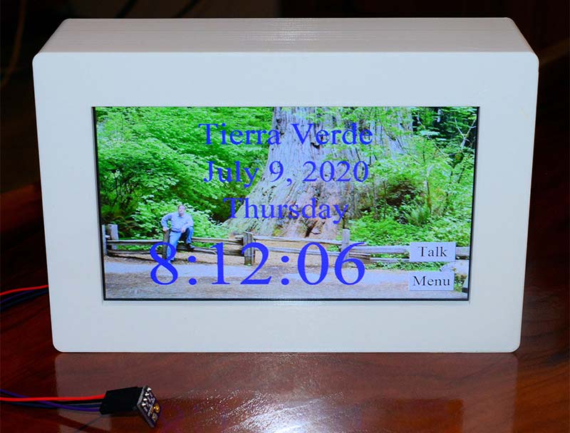
FIGURE 18. The finished seven inch Nextion display clock.
Troubleshooting
When uploading the software included in the downloads to the ESP32, be sure you’ve selected NodeMCU-32S for the Board in the Tools menu of the Arduino IDE. Double-check your port setting as well. Many of the ESP32 development boards available with the 0.9 inch pin row width need to have the small Boot switch pressed to begin the upload.
This is not true for a development board I’ve found on Amazon (recognizable by its yellow pin mounts) with 1.0 inch pin width spacing. The PCB design in the downloads will fit either model.
This circuit needs two things working correctly for it to begin functioning properly. The RTC needs to be set and running and an Internet connection via Wi-Fi are some of the first things the program does.
There are two Boolean debug variables — debug and debug_min — and by default both are assigned as true to allow Serial.print and Serial.println commands to send information to the Serial Monitor.
The Serial Monitor is found in the Tools menu of the Arduino IDE. The serial port is set to send at 115,200 baud, so remember to set that same value at the bottom of the Serial Monitor window.
There’s a five second delay built into the beginning of the startup() function to allow time to start the Serial Monitor after the upload has finished.
Viewing the Serial Monitor as the program starts should give good insight into what the program is doing.
The Nextion display will not only send things like Component IDs you have programmed into the display but will also send status and error information.
Check the Instruction Set page from the Help Menu of the Nextion Editor for these codes. If the variable debug_min is set to true (its default value), all data sent from the Nextion display will be echoed to the Serial Monitor.
Remember that the digital clock program runs on a one minute cycle, except for graphing temperature in the seven inch model which has a two minute cycle.
hen the clock starts, it may be at a point where nearly a minute will elapse before it reads new information from the Internet, so readouts may be missing or incorrect during this time.
Once the program is running satisfactorily, the debug and debug_min values can be changed to false to reduce the stream of information sent through the serial port.
Check the connections to the BME280 board on the Nextion display. Looking at the PCB with the USB connector on the ESP32 to the right and the volume shaft on the PAM8403 to the left, the four-pin header for the BME280 is laid out horizontally at the bottom of the board and has the power pins on the right. The four-pin header for the Nextion display runs vertically and has the power pins at the top.
The wire colors from the Nextion display should be black, red, blue, and yellow, running from top to bottom of the four-pin header.
Downloads
What’s in the zip?
Entire Digital Clock Program
PCB Layout
.HMI and .TFT Files