There are several key steps to setting up a telescope with a “German Equatorial Mount.” You have to level the tripod, balance the telescope with weights, align the main mirror with the small “spotting scope,” find the “latitude” for your location on earth, and then adjust the angle of the telescope for that latitude.
Another equally important step is making sure the telescope mount is always pointing towards the North Pole (“True North”). Some people use a compass and a broomstick to align their telescope. In this article, I’ll show you how to build a laser alignment circuit to easily align your telescope mount/tripod with the North Pole.
SHOW AND TELL
Figure 1 is a photo of the 3D printed laser alignment system I designed and built for my grandson’s telescope.
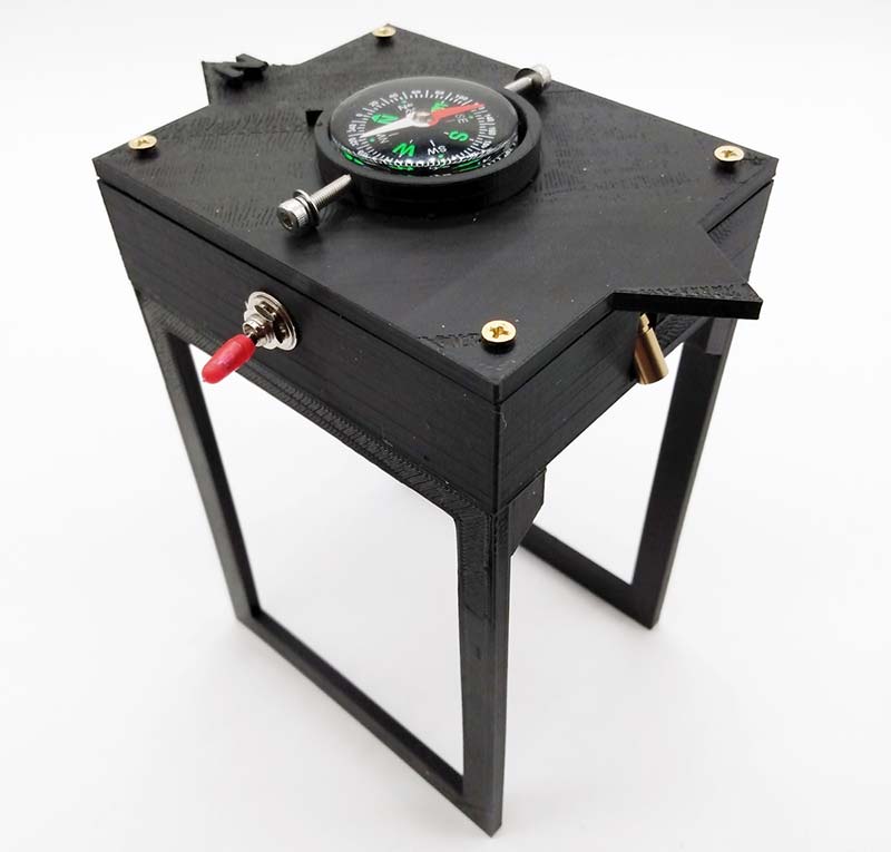
Figure 1.
Figure 2 shows the laser system in use. I just place the unit on the floor and rotate it until the red compass arrow points north. Next, I turn the toggle switch SW1 on to activate the laser.
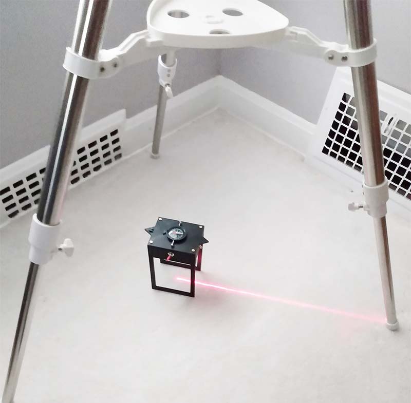
Figure 2.
Finally, I move the tripod legs (not the laser) around until the laser-line lines up with one leg of the tripod. This procedure aligns the German equatorial mounted telescope (see Figure 3) with the “magnetic” North Pole.
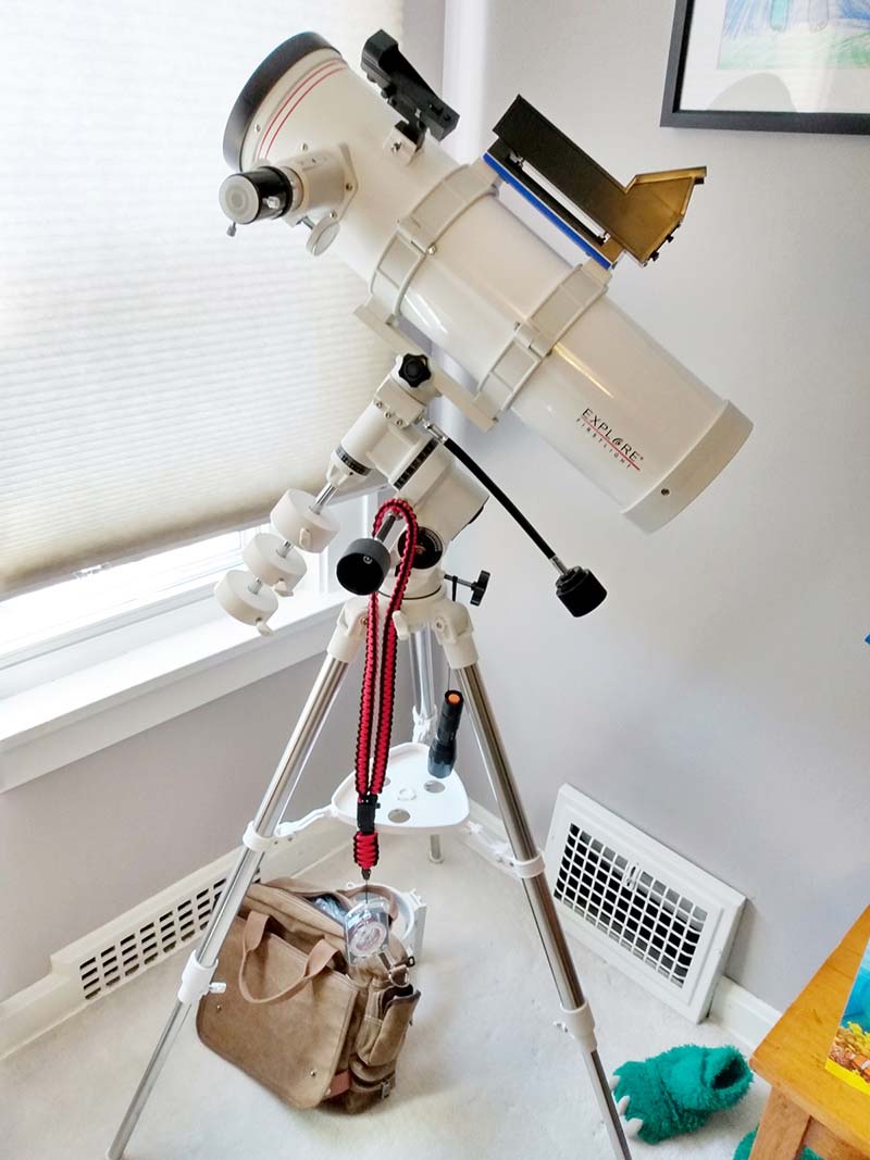
Figure 3.
Quick Review
It’s important before we start that I clarify some of the terminology used to locate objects on land and in the night sky.
If you’re a hiker, the last thing you want is to get lost in the woods. A good map can literally save your life. Terrestrial maps are based on two geographical coordinates: “latitude” (degrees north/south of the equator) and “longitude” (degrees east/west of the Prime Meridian – Greenwich, England).
In other words, your current position and/or destination points can easily be computed using latitude and longitude coordinates (for example, latitude 42° 18’ 1” north by longitude 82° 21’ 21” west).
On the other hand, latitude and longitude won’t help you find a star or planet in the night sky. Astronomers use a different coordinate system: Declination (degrees north or south of the celestial equator) and Right Ascension (hour lines east or west from the Vernal Equinox — zero hour).
So, if you know how high up in the sky a star is (declination), how far east or west it is (right ascension), and you know the correct time of day, you can locate and track a star or planet for an extended period of time.
Therefore, having a telescope with a German equatorial mount makes it easy to dial in (declination and right ascension) and locate any star above the horizon.
However, before you can go sky gazing, you need to set up the equatorial mount so it’s facing in the direction of True North (i.e., geographical North Pole) — not towards the magnetic North Pole. This is where my laser alignment system comes into play.
Unfortunately, the difference between True North (telescope north) and magnetic North (compass north) changes a few degrees every year. Just to be clear here, it’s the magnetic North Pole that physically moves a few degrees each year. The True North pole does not move.
Therefore, if the telescope is pointing at the True North Pole, finding the North Star (Polaris) in the night sky is just a matter of tilting the telescope upwards equal to your latitude. This angle varies according to where you live on the earth.
Why is this North Star so important in astronomy? Well, all the stars and planets in the sky rotate around this one star throughout the night. This is the star astronomers use as the True North position in the night sky.
I bring up all the above only to let you know my design uses a compass to find the north direction. Therefore, it will locate the magnetic North Pole instead of True North. Later in this article, I’ll show you how to adjust the compass, so it points to True North. (Unfortunately, because magnetic North physically moves a few degrees each year, this adjustment has to be done every year.)
Let’s Build It
All the 3D printed files (.stl) for this project are available in the article downloads. The three printed components are shown in Figure 4 (top), Figure 5 (bottom enclosure), and Figure 6 (stilts).
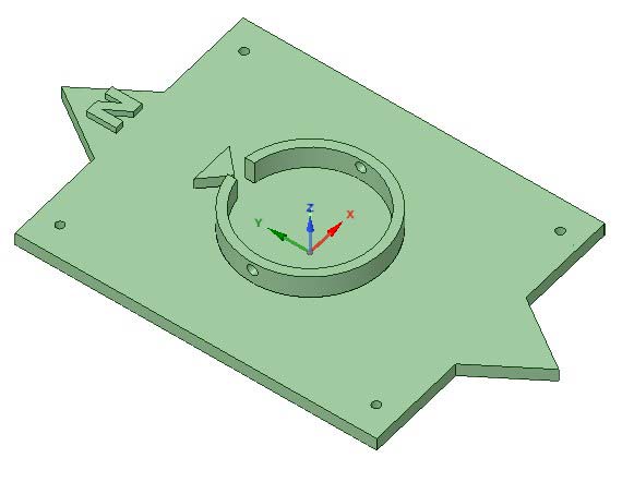
Figure 4.
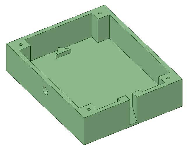
Figure 5.
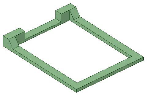
Figure 6.
On To The Circuit
Figure 7 shows the schematic for the laser alignment system.
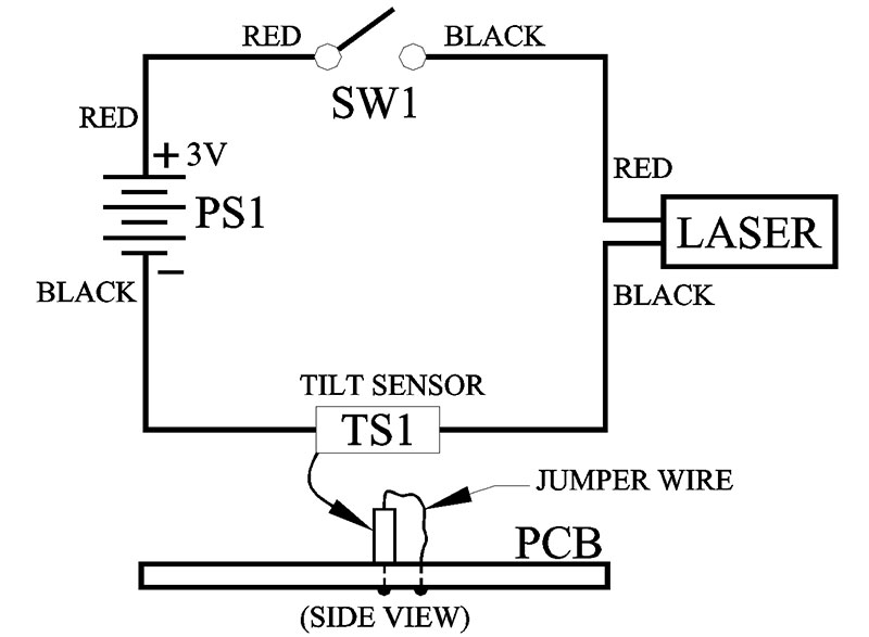
Figure 7.
Even though the power output of the laser used in this project is rated at <1 mW (Class 1), I still decided to incorporate a safety feature into the design so that the only time the laser will turn on is when the laser is facing downward towards the floor or ground. Therefore, it’s important that you mount the tilt sensor (TS1) perpendicular to the surface of the protoboard.
I suggest breadboarding the circuit to verify that the laser only turns on when you flip the breadboard over. Otherwise, it’s normally off. Mark one end of the sensor with a pen so you don’t solder the sensor upside down (I did!).
The protoboard is shown in Figure 8.
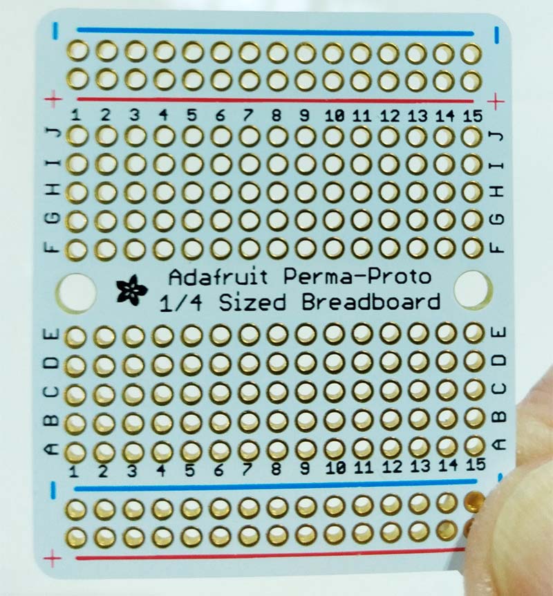
Figure 8.
Take this board and saw it in half. Half of a board is more than you’ll need for this project.
The wiring layout for the protoboard is shown in Figure 9.
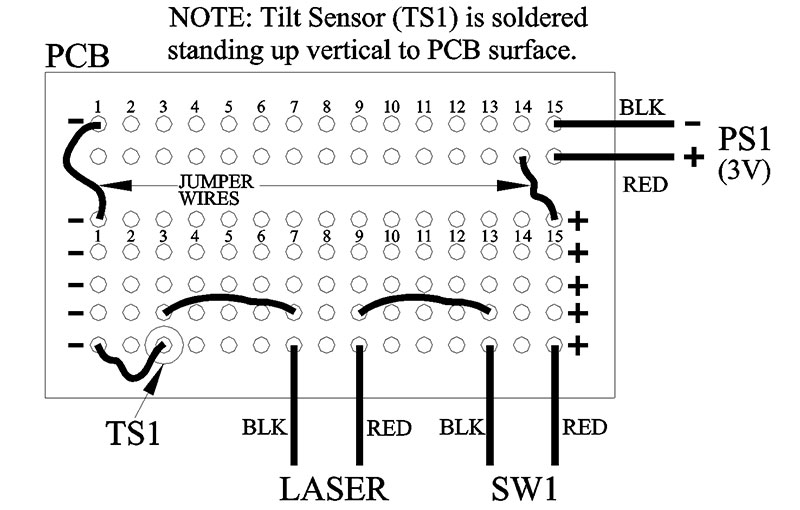
Figure 9.
Use jumper wires where needed.
Assembly
Mount the protoboard, switch SW1, and battery holder inside the enclosure as shown in Figure 10.
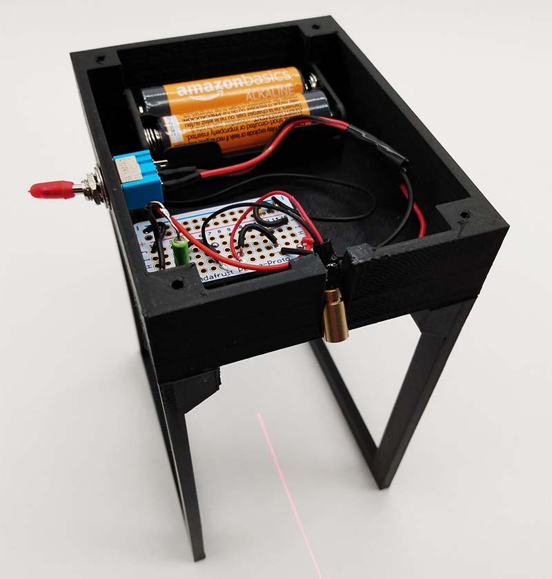
Figure 10.
The laser can be glued inside the slot, facing downward towards the floor. Be careful not to get any glue on the barrel of the laser.
The laser comes with a focusable lens. Before you glue the laser in place, twist the barrel to align the laser light in between the two stilts. Use a wooden ruler so as not to reflect any laser light towards your eyes.
Use a small dab of glue to mount the battery holder and protoboard to the inside of the enclosure. Also glue the two stilts to the bottom edges of the enclosure.
Important Step
The goal here is to align the compass and the top plate so they are both pointing towards the magnetic North for your particular location.
Using a small Allen wrench, take the two socket head screws and insert them into the two holes on the top plate as shown in Figure 11.
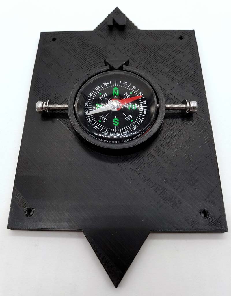
Figure 11.
Now, place the compass inside the containment well, making sure the compass can rotate freely.
True North vs. Magnetic North
I mentioned earlier that I would show you how to adjust the compass so that it points to True North instead of magnetic North. Here’s how you do it!
The difference (in degrees) between True North and magnetic North is called the “magnetic declination” error (see Figure 12).
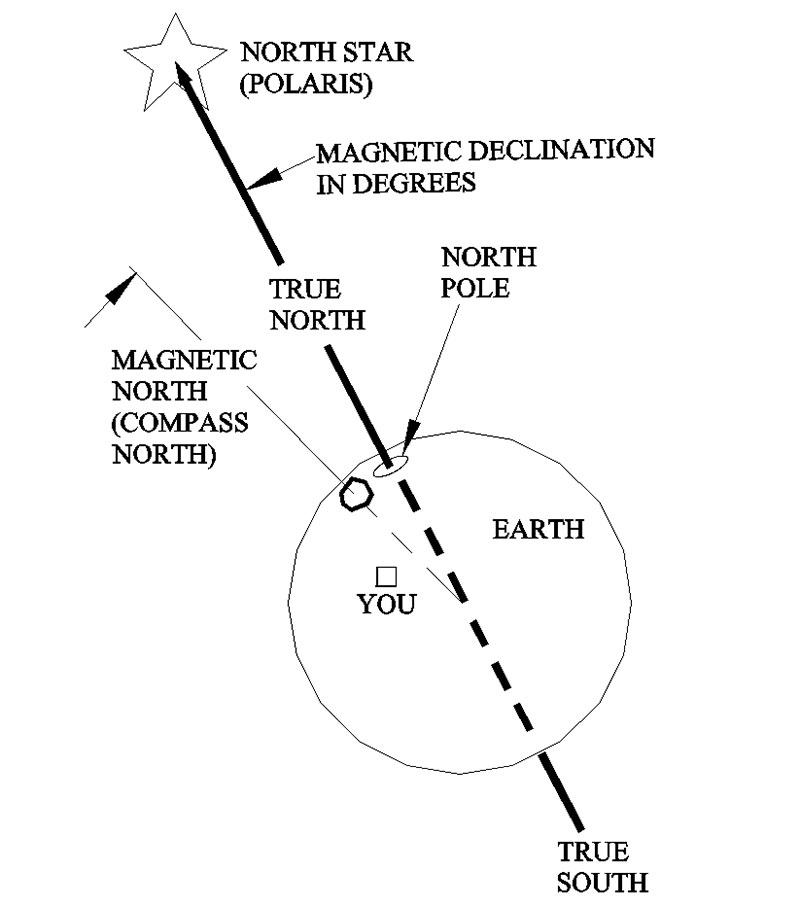
Figure 12.
Adjusting your compass so it points to True North is not that hard to do.
Normally on a more expensive compass than the one used in this project, you get a tiny key to insert into the back of it to make the adjustment. As of right now, without any adjustment, the compass used in this project will only point to magnetic North. Therefore, you’ll have to make an adjustment so that the red compass needle points a few degrees to the left or right of the magnetic North position. After you make the adjustment to the compass, it will read True North. This is what you’ll use to point your telescope in the right direction.
The adjustment procedure requires that you Google the magnetic declination for your particular location. It will be either a few degrees east or west of True North, depending on where you are.
A good place to find your magnetic declination value is the website for the National Oceanic and Atmospheric Administration (NOAA) at https://www.ngdc.noaa.gov/geomag/calculators/magcalc.shtml#declination. Just enter a street address to get your latitude and longitude.
The website will calculate the magnetic declination error for you.
Before you can adjust the compass and laser for magnetic declination, you first have to set up the compass to point to the magnetic North Pole — normal operation.
First, loosen the two socket head screws and then place the top plate in the palm of your hand. Make sure the compass can move freely. Now, rotate your body (not the compass) until the red compass arrow points to the black 3D printed arrowhead.
Next, using your two thumbs, rotate the plastic compass until the green letter N on the compass is in line with the red compass needle. All three must be in line: the red needle; the green N on the compass; and the black 3D printed arrowhead. Once aligned, press down on the compass with your thumb to lock in the position. Next, take an Allen wrench and lock down the compass with the two socket head screws. Don’t tighten the screws too tight because the compass has a plastic shell.
Your compass and laser line are now adjusted and ready for use. This is the normal procedure for aligning the compass and laser with the magnetic North Pole.
Next, take the four brass screws and attach the top plate to the enclosure, making sure you line up the small black arrowhead inside the enclosure with the letter N printed on the top plate. The small brass screws are not that strong and can shear off if there’s too much resistance during assembly. Drill out the mounting holes if necessary.
Here’s how to adjust your compass to find True North: Place the assembled unit on the floor/ground, making sure the red compass needle is pointing north. While looking at the compass, slowly rotate the unit left or right adding or subtracting the number of degrees based on the magnetic declination error for your location. This is the compass position (True North) you should be using every time you set up the telescope for star gazing.
Finally, as a reminder, you’ll have to adjust the compass for the magnetic declination error yearly — no matter how expensive of a compass you buy.
Happy gazing! NV
NOTE: If you would rather not have to do the above adjustment every time you set up the telescope, buy a good compass that has a key and adjustment hole just for this purpose. Of course, you will have to redesign the top plate and make a new 3D print.
Parts List
| PART |
QTY |
DESCRIPTION |
PART NO |
SOURCE |
| TILT SENSOR |
1 |
Metal Ball Switch Tilt Angle Sensor |
SW-200D |
Amazon |
| LASER |
1 |
Adjustable Focus, 6 x 13 mm, 650 nm, 1 mW, Red ‘Line’ Diode Laser |
n/a |
ALIEXPRESS |
| COMPASS |
1 |
35 mm Diameter, Liquid Filled |
MAG-150 |
Educational Innovations |
| SW1 |
1 |
DEVMO SPST Mini Toggle Switch with Wires, ON/OFF, Metal, 1/4” Drill Hole, Pre-Wired with 12” Leads, 12V, 125V, 250V |
n/a |
Amazon |
| PCB |
1 |
Printed Circuit Board, 3 pack |
ADA589 |
Amazon |
| PS1 |
2 |
Power Supply, AA Batteries (non-rechargeable batteries) |
n/a |
Amazon |
| BAT HOLDER |
1 |
WAYLLSHINE, 12 Pieces, 2 x 1.5V AA, ABS Plastic Battery Holder Case Box, with Red and Black Wire Leads – 5.7” L |
n/a |
Amazon |
| SCREWS |
2 |
M3 x 14 mm Stainless Steel Hex Socket Head Cap Screws, with Spring Washer Head Cap Screws, with Spring Washer |
n/a |
Amazon |
| SCREWS |
4 |
#4 x 1/2” Wood Screw, Flat Head Phil |
9034254 |
Amazon |
| GLUE |
1 |
DUCO Cement, Multi-Purpose Household Glue – 1 fl oz, dries clear |
62435 |
Amazon |
Downloads
What’s In The Zip?
3D Print Files (.stl)