This three-phase motor can be created on a breadboard for under $15 in parts. The motor can be used to explore the motor concepts and theory used in electric vehicles.
To build the motor, all that’s required is gauge 22 AWG solid hook-up wire, six (SBCP-47HY330B) inductors, a nine volt battery, a solderless breadboard, and a compass (Figures 1 and 2).
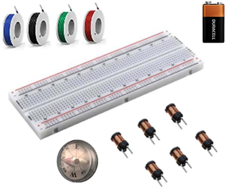
FIGURE 1. Parts.
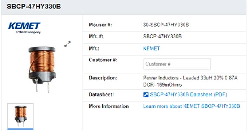
FIGURE 2. Coil.
Place the compass on the breadboard and position the six inductors around it so that they’re evenly spaced (Figure 3).
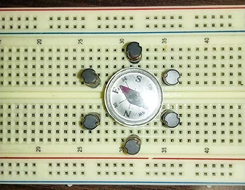
FIGURE 3. Coil placement.
Make certain that each lead of the inductors is in separate numbered rows and that there’s access to other contact points along each row. Make certain that each inductor is pushed fully in and sits flat against the breadboard.
Designate the inductors L1 through L6. The motor will be wired in a WYE configuration. Wires should be stripped 1/2 inch and go fully into the breadboard. Wires should be kept as short as possible and run to the side of the inductor away from the compass. It’s important to note that this is not simply an electrical circuit but a mechanical device dealing with physical forces.
The U, V, and W are common designations for the labeling of motor phases (Figure 4).
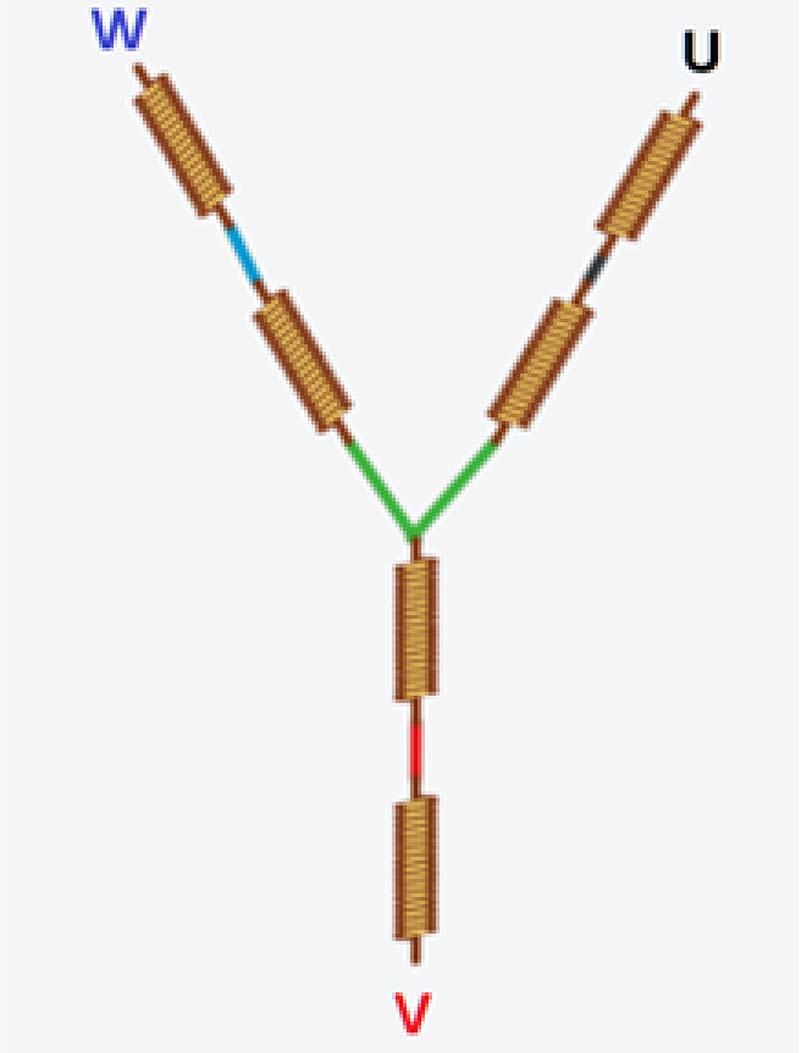
FIGURE 4. WYE configuration.
L1 and L4 make up phase U; L2 and L5 make up phase V; and L3 and L6 make up phase W (Figure 5).
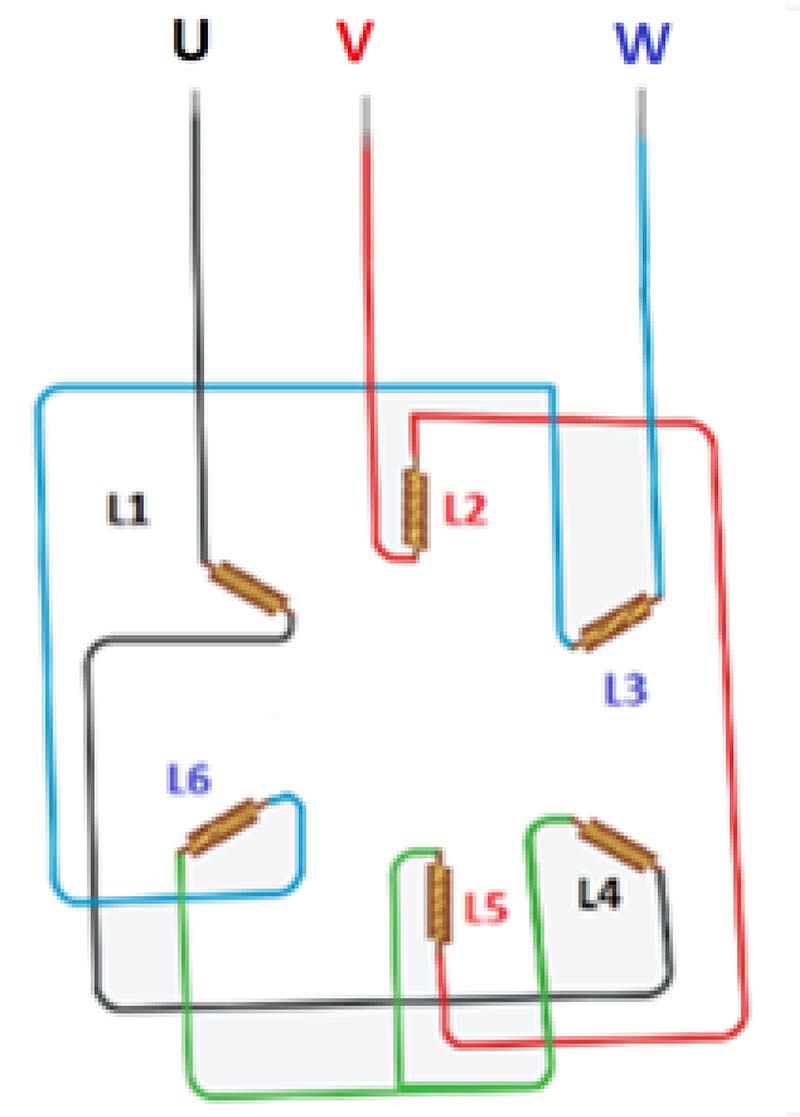
FIGURE 5. WYE wiring layout.
The motor will be constructed one phase at a time, checking for both electrical polarity (positive and negative) as well as for magnetic polarity (north and south). Refer to Figures 6 and 7.
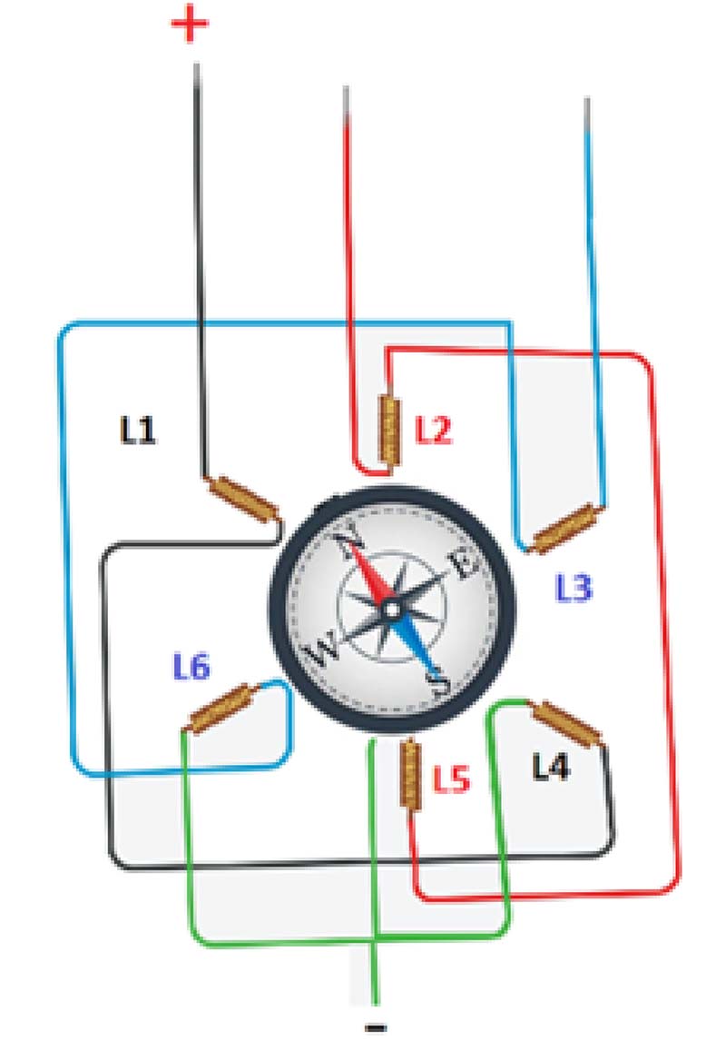
FIGURE 6. Compass deflection phase.
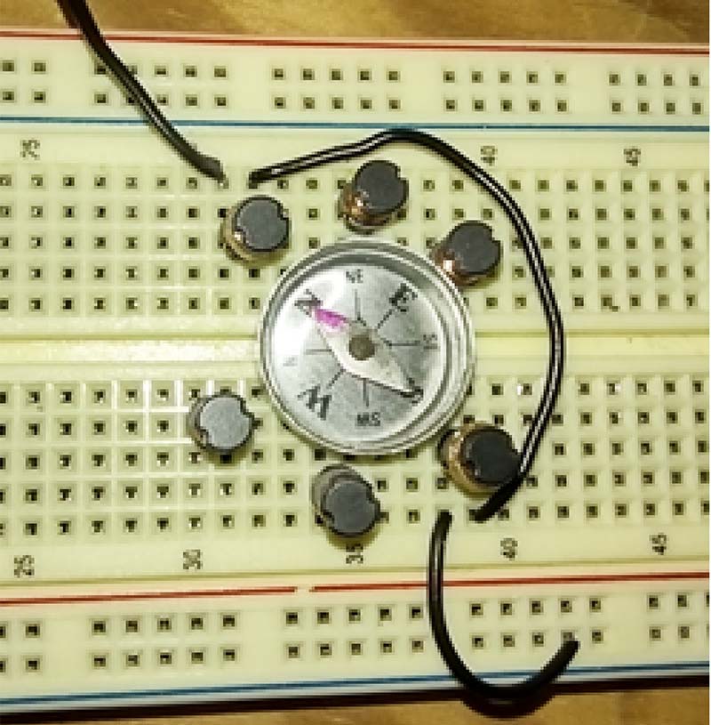
FIGURE 7. Phase U photo.
Connect a wire designated “U” to one side of L1. Connect a wire from the other side of L1 to L4. Connect the other lead of L4 to the common bus at the bottom of the breadboard.
Connect the positive lead of the 9V battery to U and the negative lead to the common bus. The red arrow of the compass should point towards the U lead. If the red arrow is not pointing towards the U lead, try flipping the leads of the inductors one at a time until it does. Switch the polarity of the battery. The blue arrow should point towards the U lead. Connect a wire designated “V” to one side of L2. Connect a wire from the other side of L2 to L5. Connect the other lead of L5 to the common bus at the bottom of the breadboard. Refer to Figures 8 and 9.
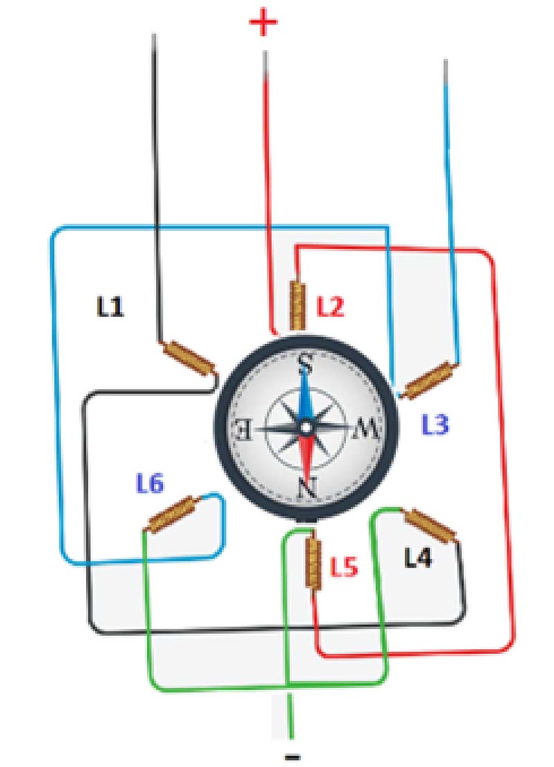
FIGURE 8. Compass deflection phase V.
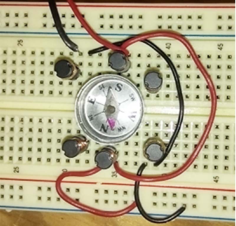
FIGURE 9. Phase V photo.
Connect the positive lead of the 9V battery to “V’ and the negative lead to the common bus. The blue arrow of the compass should point towards the V lead. If the blue arrow is not pointing towards the V lead again, try flipping the leads of the inductors L2 and L5 one at a time until it does. Switch the polarity of the battery. The red arrow should point towards the V lead. It’s important to note here that in three-phase motors, the magnetic pole is shifted every other pole.
Connect a wire designated “W” to one side of L3. Connect a wire from the other side of L3 to L6. Connect the other lead of L6 to the common bus at the bottom of the breadboard (Figures 10 and 11).
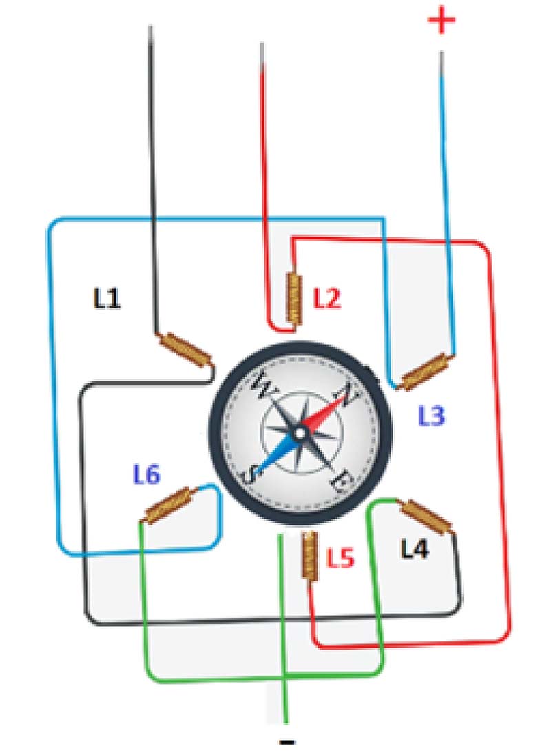
FIGURE 10. Compass deflection phase W.
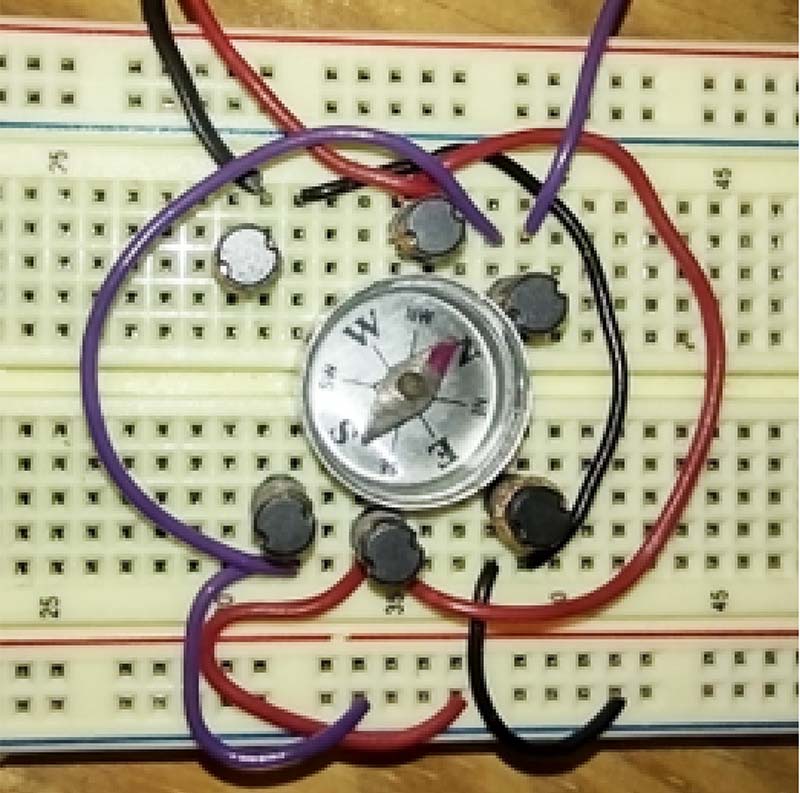
FIGURE 11. Phase W photo.
Connect the positive lead of the 9V battery to W and the negative lead to the common bus. The red arrow of the compass should point towards the W lead. If it isn’t pointing towards the W lead, try flipping the leads of the inductors L3 and L6 one at a time until it does. Switch the polarity of the battery. The blue arrow should point towards the W lead.
The motor is now complete. You can simulate a three-phase AC signal with a microcontroller or with three single-pole/double-throw switches. The speed of an AC motor depends on the frequency of the input signal. It takes six steps for the motor to complete one revolution. The six steps are shown in Table 1.
| STEP |
PHASE U |
PHASE V |
PHASE W |
| 1 |
POSITIVE |
NEGATIVE |
NEGATIVE |
| 2 |
POSITIVE |
POSITIVE |
NEGATIVE |
| 3 |
NEGATIVE |
POSITIVE |
NEGATIVE |
| 4 |
NEGATIVE |
POSITIVE |
POSITIVE |
| 5 |
NEGATIVE |
NEGATIVE |
POSITIVE |
| 6 |
POSITIVE |
NEGATIVE |
POSITIVE |
TABLE 1.
If you switch any two of the leads, the motor will change directions. If you’re unable to find a compass small enough to fit on the breadboard and leave space for the inductors, you can always place a larger compass on top of the inductors.
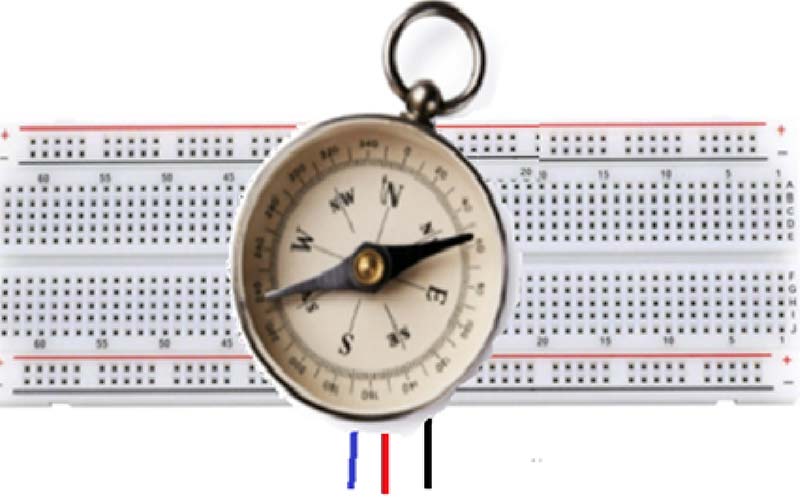
FIGURE 12. Compass sitting on tip of circuit.
Have fun experimenting! NV