Here’s a simple wireless doorbell pager circuit you can build for those who have lost their hearing. Its construction consists of a wireless doorbell receiver circuit and one 555 IC configured as a “one shot” that’s used to trigger a small vibrating pager motor. Although the final unit is a little bigger than a normal sized pager, the 3D printed enclosure presented here can still fit comfortably into a shirt or pants pocket. This is a great device for those who need to know when an Amazon package or a friend/relative has arrived at the front door.
DON’T REINVENT THE WHEEL
Rather than trying to design a whole new wireless doorbell system from scratch (Arduino, Raspberry Pi, etc.), it’s much easier to just “repurpose” an existing circuit. It’s the same thing the drug companies are doing today by repurposing old FDA approved drugs to combat the corona virus.
With that in mind, I decided to cannibalize a cheap ($10) battery operated wireless doorbell by removing the circuit board (receiver), speaker, and antenna (see Figure 1, Figure 1a, and Figure 1b).
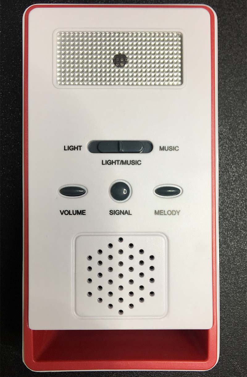
FIGURE 1.
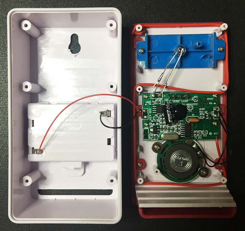
FIGURE 1A.
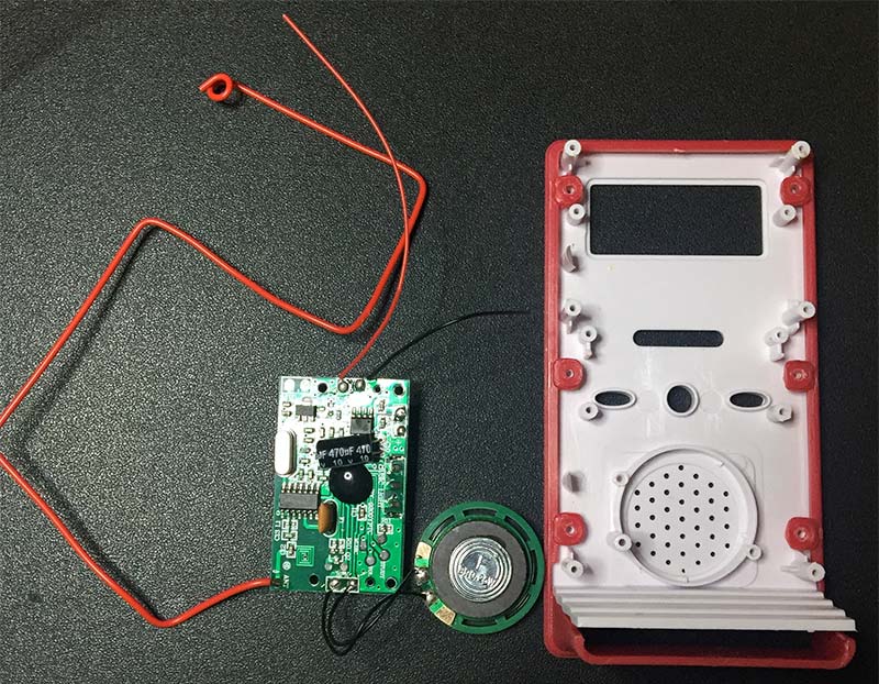
FIGURE 1B.
HOW IT WORKS
Figure 2 shows the complete transmitter (doorbell ringer) and receiver/pager circuit.
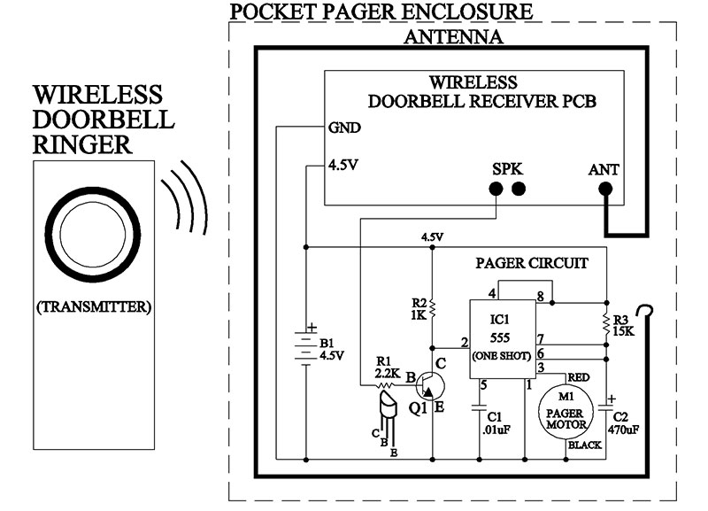
FIGURE 2.
As you can see in the top portion of the diagram, I connected the ground (GND), 4.5V, and one speaker (SPK) wire from the doorbell receiver printed circuit board (PCB) to my pager circuit using only three connections.
The pager circuit works as follows: IC1 (555) is configured as a monostable timer (one shot). If there’s a high to low voltage transition on pin 2 (trigger pin), then output pin 3 will go high for a set period of time. The time period (1.1 x R3 x C2) is controlled by resistor R3 (15K) and capacitor C2 (470 µF). This combination gives a 7.75 second delay.
The starting sequence begins when someone at the front door pushes the wireless doorbell button (transmitter). Next, the doorbell receiver PCB picks up the signal from the doorbell ringer and sends a ring tone (i.e., voltage) to the speaker. The speaker voltage switches from zero volts to 1.6 volts.
This low to high transition is applied to the base of Q1 through R1. This turns on transistor Q1 (NPN). Since the collector voltage and pin 2 are normally sitting at 4.5V, the collector of Q1 will go low (0V). Since pin 2 (trigger) is connected to the collector, it will see this high to low transition and force pin 3 (output) to go from a low to a high state. Now, since pin 3 is connected to a pager motor, the motor will vibrate for 7.75 seconds. After 7.75 seconds, pin 3 will go low and turn off the pager motor.
CONSTRUCTION
Start the construction by removing the doorbell receiver PCB, speaker, and antenna from the store-bought enclosure as shown in Figure 1b.
Next, remove the speaker and discard it, but leave the attached wires on the receiver PCB as long as possible (i.e., clip the wires off near the speaker). The speaker is not necessary because one wire will be connected to R1 on the pager circuit to supply the required 1.6 volts to transistor Q1.
In turn, cut the battery wires off as close to the battery compartment as possible, leaving the power wires (+/-) on the receiver PCB as long as possible.
Now it’s time to solder all the components onto the pager PCB. Take the printed circuit board and lay out the components as shown in Figure 3.
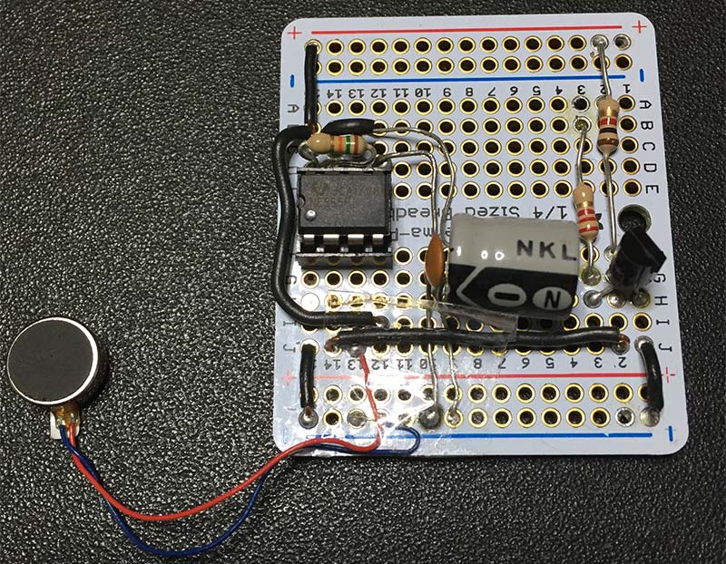
FIGURE 3.
This is the point in the construction that requires attention to detail. Make sure you verify the correct orientation of transistor Q1 and capacitor C2 before soldering them into the pager PCB.
Unfortunately, the wires attached to the pager motor (M1) are really thin. So, after soldering them into place, take some scotch tape and tape the pager motor leads (red/black) to the pager PCB. This will stop the motor vibrations from ripping the wires out of the PCB during testing and operation.
Now, connect the 4.5V and ground (GND) connections on the receiver PCB to the 4.5V and ground connections on the pager PCB as shown in Figure 4 (red wires to + and black wires to GND). Do the same thing for the black and red battery holder leads.
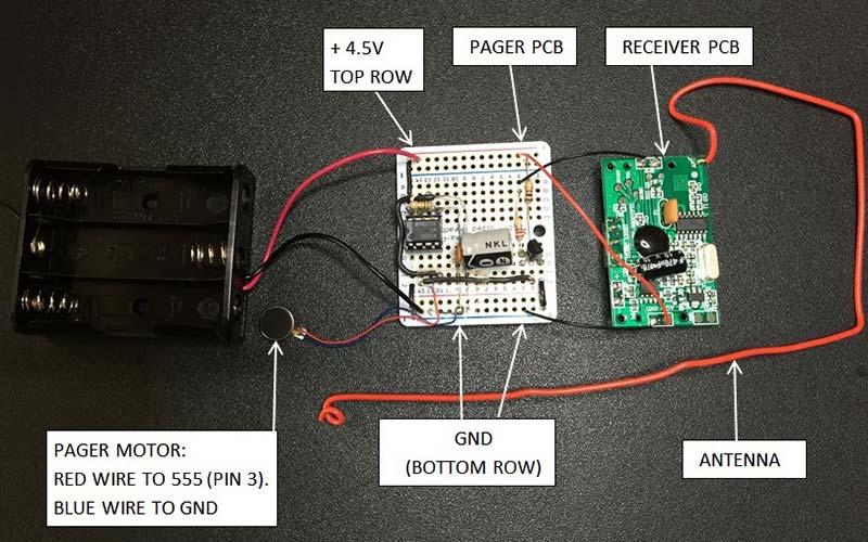
FIGURE 4.
Next, take one wire from the speaker connection (SPK) on the receiver PCB and solder it to the top of R1. Clip the other wire off.
It’s important to put a wide strip of painter’s or masking tape in between the receiver PCB and the pager PCB before placing them into the enclosure. This will isolate the electrical components on both PCBs and reduce the possibility of a short circuit.
[I didn’t use the original enclosure that came with the wireless doorbell for the pager because it was too bulky to fit inside a shirt pocket.
So, I 3D printed a smaller box (L=4-1/2”, W=2-1/2”, H=7/8”) that is just a little bit bigger than a regular sized pager.]
Now, insert the pager PCB, receiver PCB, antenna, and battery holder into the enclosure as shown in Figure 5.
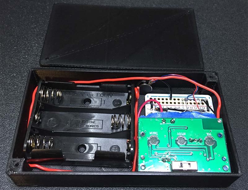
FIGURE 5.
Leave a little space around the battery holder to make room for the antenna.
Next, attach the pager motor to the inside wall of the enclosure using the self-stick tape on the back of the motor.
Finally, hot glue the battery holder in a couple of spots along one edge. All done! Figure 6 shows the final product ready for action. NV
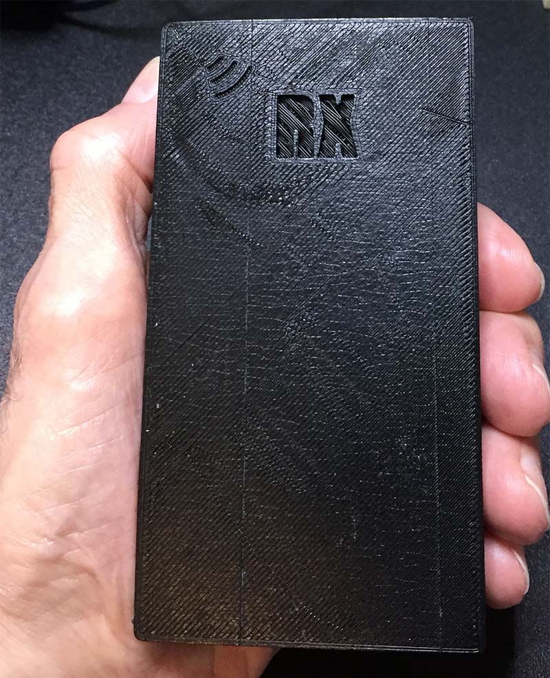
FIGURE 6.
QUICK TROUBLESHOOTING GUIDE
- Double-check your wiring layout against the diagram in Figure 2.
- Use a magnifying glass (microscope is better) to check for bad solder joints and solder bridges on the pager PCB. These are very common problems.
- Use a digital multimeter and verify that 4.3V-4.5V is present at the power connections on the receiver PCB (marked 4.5V, GND), pager PCB (top row), AA battery terminals, and pin 8 (555).
- Once the circuit is activated (doorbell ringer pressed), pin 2 (555) should go from a high to low transition. In turn, pin 3 should go from a low to a high, and stay high for 7.75 seconds.
- Try a new 555 IC; check for bent pins.
SPECIAL NOTES
- The time the pager motor is on (vibrating) can be adjusted by replacing R3 with a 50K potentiometer. As you adjust the pot, use your phone’s stopwatch to time the motor’s vibrations in order to get the number of seconds you need. Once you know the required resistance, replace the pot with a single 1/4 watt resistor. Just remember, the longer the vibration time, the more of a drain it will be on the batteries.
- The range of the wireless doorbell unit is about 180 meters in an open area. Of course, that range will be lower depending on the number of walls in between the doorbell ringer and pager.
- If you plan on building this project, it would be advisable to use rechargeable AA batteries. When compared to cheap mass market AA batteries, Soluser and Eneloop batteries appear to maintain their voltage level during most of the discharge time. Don’t use 9V batteries since they only have a 500 mAh (milli-Amp-hour) power rating compared to the 2,000 mAh to 2,850 mAh of AA batteries.
- Since there is no on/off switch for the pager unit, the pager will be on 24 hours a day. To be safe, recharge the AA batteries every two or three days. Depending on what type of AA battery and ‘mAh’ power rating you use, the recharge time can last up to 10 days. You’ll know if the batteries are low by stepping outside and ringing the doorbell. If the pager’s vibration seems weak, it’s time to recharge the batteries.
- If for some reason the battery operated wireless doorbell described in this article becomes unavailable (Amazon), just apply the same techniques I described here with a different battery operated wireless doorbell model. Look for the smallest doorbell enclosure. This usually means the circuitry inside (PCB) is also small in size, making it easily adaptable to use inside a pager enclosure.
- Don’t be tempted to substitute IC1 (555) with the lower standby current of a 7555. The datasheet for the 7555 shows an extremely low “standby” current of 60 µA (.000060A). Unfortunately, the output voltage (pin 3) is lower than a regular 555 and is insufficient to run the pager motor (M1).
- Don’t forget to remove the sticker from the outside doorbell ringer (transmitter) battery or it won’t work.
Parts List
| QTY |
ITEM |
DESCRIPTION |
PART# |
SOURCE |
| 1 |
R1 |
Resistor, 2.2K, 1/4W |
791-RC1/4-222JB |
Mouser |
| 1 |
R2 |
Resistor, 1K, 1/4W |
791-RC1/4-102JB |
Mouser |
| 1 |
R3 |
Resistor, 15K, 1/4W |
791-RC1/4-153JB |
Mouser |
| 1 |
C1 |
Capacitor, .01 µF |
594-D103Z25Z5VF63L6R |
Mouser |
| 1 |
C2 |
Capacitor, 470 µF, Electrolytic |
667-EEU-FR1E471B |
Mouser |
| 1 |
IC1 |
555 Timer, Eight Positions, DIP |
595-NE555P |
Mouser |
| 1 |
IC1a |
IC Socket, Eight Positions, DIP |
575-144308 |
Mouser |
| 1 |
Q1 |
Transistor, NPN, 2N2222A |
610-PN2222A |
Mouser |
| 1 |
M1 |
Vibration Motor |
2234-LS-00046-ND |
Digi-Key |
| 1 |
PCB |
Quarter-Size Breadboard PCB |
ADA589 |
Amazon |
| 3 |
B1 |
AA Battery, 1.5V (Rechargeable) |
|
Optional |
| 1 |
B1a |
AA Battery Holder |
12BH331-GR |
Mouser |
| 1 |
B1b |
AA Battery Charger |
|
Optional |
| 1 |
|
Wireless Doorbell |
80-3055L |
Amazon |