In Part 1, we looked at a test circuit that had 12 LEDs. Using Charlieplexing, we ran those LEDs with only four I/O lines and determined that expanding the LED matrix to 14 I/O lines would enable us to individually control 182 LEDs. We also looked at how to incorporate the reading of four pushbuttons by connecting them to the LED matrix with a handful of other discrete components. This allowed us to read the buttons without using any additional I/O lines. The final two I/O lines will be used to run the alarm buzzer and read the 60 Hz coming from the AC-to-AC wall wart.
This time, we’ll expand the LED matrix to run the 182 LEDs that the clock uses and make a printed circuit board (PCB) for the clock. Then, we’ll wrap it up with a discussion of how the software works and put the finishing touches on our unique timepiece. Let’s get started.
The Printed Circuit Board
I decided a PCB would be best to have for the final circuit, due to the large number of LEDs and the need to arrange them and the resistors and diodes in a circular pattern. I wanted to manually route the traces so that the only traces visible from the front of the clock are the Charlieplexed lines, which would be laid out as concentric traces on the front of the board among the LEDs. I played around with a number of PCB design programs and decided to use DipTrace as I found that it could most easily do what I wanted.
DipTrace has a schematic capture module where I created the schematic for the clock. Then, DipTrace transfers the schematic to the PCB layout module. To arrange the LEDs and other components in a precise circular pattern, I created a spreadsheet in Excel to calculate the position and rotation of the components. I entered these values into the Properties field of each component. Once all the components were in place, I manually routed the traces. DipTrace has a 3D rendering tool to show what the completed board will look like (Figure 1).
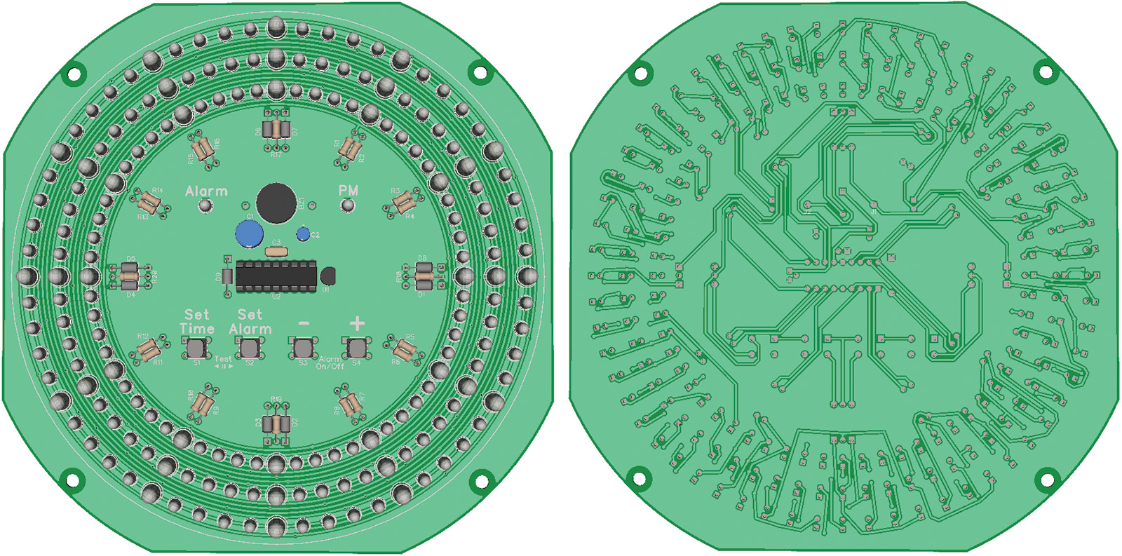
FIGURE 1. 3D rendered PCB design (front and back).
I used Bay Area Circuits (see Resources) to make the circuit board as they had a student special that allowed me to make a single board for a very reasonable price. DipTrace generated the necessary files to send to Bay Area Circuits so they could make the board. While I was waiting for the board to be made, I ordered more parts (mostly LEDs) to build the clock.
Building and Testing the Clock
It took me about four hours to solder all the components onto the PCB (Figure 2).
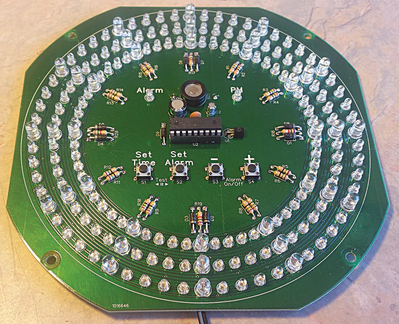
FIGURE 2. Assembled circuit board.
Once I was done, I adjusted the code that I had written for the test circuit to work with the additional LEDs and button. It turned out there were about a dozen or so LEDs that wouldn’t light up. I took note of which ones were not coming on and realized their anodes were all connected to the same line.
I checked that line for continuity to the current-limiting resistor and to its I/O pin on the microcontroller. That all looked good. Then, I thought I had a bad microcontroller, so I replaced it. I was pretty confused when that didn’t fix it either. I checked the code, but couldn’t find any issue there. Finally, I realized what the problem was.
Somewhere along the way, I had reassigned the I/O pin that the buzzer was connected to. Instead of connecting it to RA4, I had connected it to RB7. I think I did this because the RB7 pin was physically closer to the location on the board that I wanted to place the buzzer. I must have made that swap early in the design, as the test circuit has the buzzer connected to RB7 as well.
The result was that RA4 was driving the Charlieplex LED matrix. However, RA4 is unable to source current, so half the LEDs connected to this line would not light. I had to swap the RA4 and RB7 lines. I did this by cutting some traces and installing some jumper wires on the back side of the PCB (Figure 3). After making the adjustments in the code, everything was working.
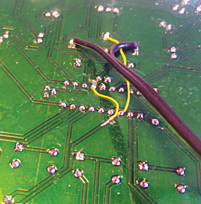
FIGURE 3. Circuit board rework.
I still had issues with some LEDs glowing faintly during operation. I was unable to completely eliminate the glow, but greatly reduced the brightness with adjustments to the code. The glow was caused by a combination of the voltage divider network and the fact that I couldn’t activate outputs on both Port A and Port B at the exact same time. Once one was set, it took a couple of instruction cycles to set the other one. The end result was that the glow was barely perceptible in a very dark room, which I felt was quite acceptable.
The Final Circuit
The final circuit is basically an expanded version of the test circuit, which we went over in detail last time. Figure 4 shows the power supply, which is identical to the test circuit.
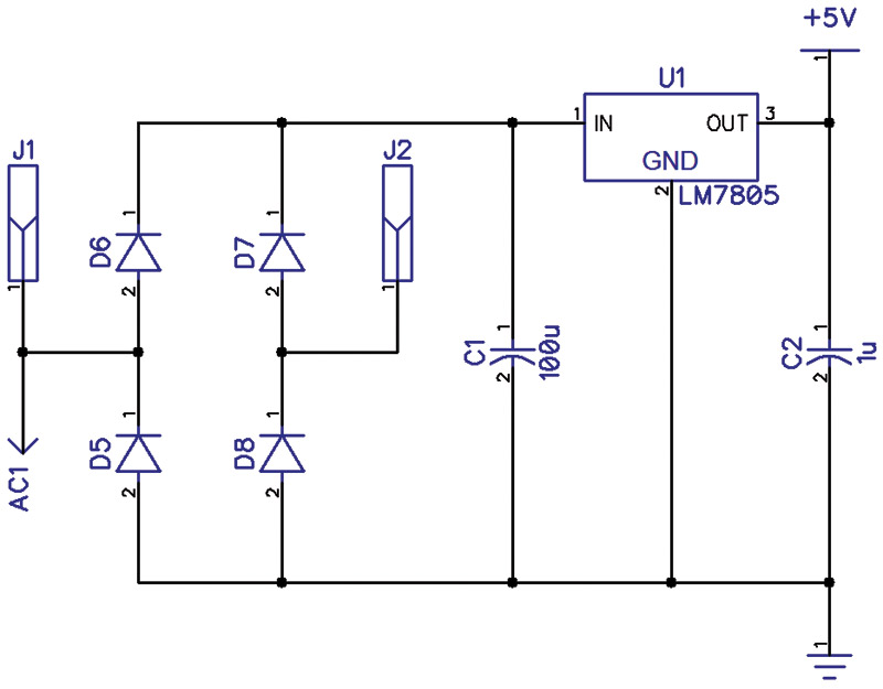
FIGURE 4. Power supply schematic.
Figure 5 shows the microcontroller.
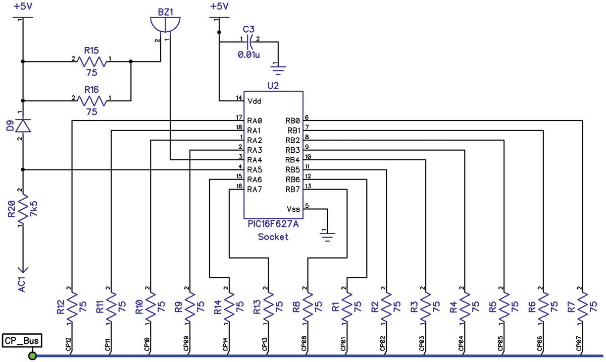
FIGURE 5. Microcontroller schematic.
R1-R14 are the current-limiting resistors for the Charlieplex LED matrix (CP_Bus). The buzzer is connected to the correct I/O line RA4 and now has 37.5Ω in series instead of 150Ω. R20 is the current-limiting resistor for the 60 Hz input line and D9 provides clamping to +5V.
Figure 6 is the Charlieplexed LED matrix — 182 LEDs connected to the 14 line CP_Bus. It still amazes me that this even works!
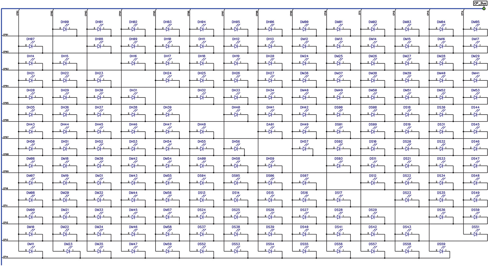
FIGURE 6. LED matrix schematic.
The four pushbuttons are shown in Figure 7. The switches are read on CP12, which is connected to RA0 — another analog input line on the microcontroller. A simple change in the code connects RA0 to the internal comparator instead of RA2 used in the test circuit.
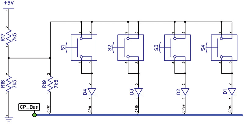
FIGURE 7. Pushbutton schematic.
The Software
I wrote the microcontroller program in assembly language. I chose this because I was already very familiar with Microchip’s PIC assembly language, and I needed precise control over the timing of certain parts of the program. It also helped that Microchip’s MPLAB Integrated Development Environment (IDE) — which is used to compile assembly language — is available from their site free of charge (see Resources).
To make writing, debugging, and editing the software easier, I broke the program up into different sections, each in its own file. The software source files are available with the article downloads. When you look at the code, you’ll see that I’m a firm believer in putting lots of comments in my code!
The Interrupt Routine
Timing issues are crucial to the operation of the clock. It must keep correct time which is accomplished by monitoring the 60 Hz line signal coming from the wall transformer. In addition, since only one LED can be lit at a time, the multiplexing of the LEDs must be carried out fast enough that the human eye cannot detect any flicker, and with precise timing so that the LEDs appear consistent in brightness. For example, the brightness of the Second, Minute, and Hour LEDs should not change when the Alarm LED is turned on or off.
I used an interrupt routine to accomplish these tasks (see interrupt.inc). The subroutine at initInt sets up Timer0 to interrupt the processor every 256 instruction cycles, or every 256 μs. This creates a “clock tick” so that events can occur at a fixed and reliable rate. initInt also sets up the programmable voltage reference and comparator for the reading of the pushbuttons and performs various other file register initializations. Finally, it enables the interrupt routine, appropriately labeled Interrupt.
Eight interrupt cycles (tracked by register intPWMcount) are used to drive each of five LEDs: Seconds, Minutes, Hours, Alarm, and PM. This time is allocated whether or not the LED is to be turned on. I wrote the interrupt routine so that each LED could be turned on any number of the eight interrupt cycles, allowing fine-tuned adjustment to its brightness by varying its on time — otherwise known as pulse width modulation (PWM).
Since there were six different LEDs used (three different colors in two different sizes), I anticipated that some LEDs might appear brighter than others, and planned on using this feature to fine-tune the brightness of the various LEDs. It turned out that the brightness of the LEDs was fairly close to each other, so I only used the PWM registers to fully turn on each LED for all eight interrupt cycles or to fully turn it off. Each of the five LEDs is turned on in sequence, with the register intLEDCount keeping track of which LED is active. Therefore, each lit LED is turned on for 2.048 ms each multiplexing cycle.
After eight interrupt cycles, the LED is turned off and the next interrupt cycle is dedicated to reading a pushbutton. The value of intLEDCount (if it is between 1 and 4) determines which button is read. If it has any other value, no button is read during that interrupt. The button is read by bringing the line that the button is on low and reading the value returned by the comparator. The status of the button is stored for use by the main routine.
In addition, its current status is compared to its previous status and if it has changed, then a button-pressed or button-released flag is set as appropriate. When the main routine processes the pressing or releasing of the button, it resets the flag. In the case of the [+] and [-] pushbuttons, as long as the button is held down, the interrupt will continue to set the button-pressed flag in accordance with the values in delayTable and dNumTable.
These tables are found in tables.inc and they define respectively the number of multiplex cycles to wait and the number of times to repeat before advancing to the next entry of the tables, where the repeat speed increases.
It takes nine interrupt cycles to light each LED: eight cycles for lighting the LED plus one cycle for reading a button. Since there are a total of five LEDs to cycle through, each multiplexing cycle takes 45 interrupt cycles or 11.52 ms. This period is equivalent to 86.6 Hz which is fast enough that the human eye cannot distinguish any flickering.
The interrupt routine also monitors the 60 Hz line and drives the buzzer. After counting 60 transitions of the 60 Hz line, the interrupt routine advances the time by one second by calling incSecTime in time.inc. When the buzzer needs to be driven, the interrupt alternately drives the buzzer line high and low, each for the duration of an interrupt cycle. The result is that the buzzer is driven by a signal with a period of two interrupt cycles for a total of 512 μs or a frequency of 1,953 Hz. This is very close to the buzzer’s resonance frequency of 2 kHz.
The Main Routine
The interrupt routine takes care of the minutiae of multiplexing the LEDs with precise timing, monitoring the buttons and 60 Hz, keeping time, and sounding the buzzer. This leaves the main routine (in clock.asm) to take care of the “big picture” part of the program, in a foreground/background type of program structure. The main routine responds to the buttons and handles the setting of the time and alarm, and the sounding, snoozing, and silencing of the alarm.
If the [Set Time] or [Set Alarm] buttons are held down, the main routine monitors the button-pressed flags for the [+] and [-] buttons and increases or decreases the time or alarm by one minute accordingly. It calls incMinTime, decMinTime (in time.inc), incMinAlrm, or decMinAlrm (in alarm.inc) as appropriate.
The main routine monitors the simultaneous pressing of the [+] and [-] buttons and toggles the alarm-on flag and LED. The main routine checks when the current time has reached the alarm time and if the alarm is on. It also continually checks the snooze time and the alarm silence time. If the alarm is to be sounded, it simply sets a flag or resets it to silence the alarm. The interrupt routine monitors the flag and drives the buzzer accordingly.
The main routine also does all the lookup and decoding of the Port and Tris values for the LEDs. It does this when the time advances a second, as well as during the setting of the time and alarm. To conserve program space, I used a two-step lookup approach.
Each LED has a single byte that is returned from the lookup tables (tables.inc) under the heading “Output Tables.” The upper nibble contains the line number that is to be driven high and the lower nibble contains the line that is to be driven low. Each nibble is in the range of 1..14 decimal. The nibbles are then looked up using the tables under the heading “Charlieplex Port Masks” to calculate and set the Port and Tris values.
To set the Port and Tris values, the main routine calls timeLEDout or alrmLEDout (in led.inc) as appropriate. For each LED to be lit, these routines perform the lookups outlined above and calculate the Port and Tris values for both Port A and Port B. The Port and Tris values are not sent to the actual Port and Tris registers but are stored in shadow registers. The interrupt routine copies the shadow registers to the actual Port and Tris registers at the appropriate time for each LED.
Two additional files — definitions.inc and registers.inc — contain definitions for constants, file registers, bit assignments, time calculations, and port definitions. I’ve also included clock.hex which can be used to program a chip without having to assemble the program.
What if your electric utility runs at 50 Hz instead of 60 Hz? A small change in the software will allow the clock to run using a 50 Hz reference instead. In the definitions.inc file, find the line that reads "#define acPerS .60" and change the .60 to .50. That's all there is to it!
The Completed Clock
I had a friend (who is a retired cabinet maker) make a wooden frame for the clock out of Medium-Density Fiberboard (MDF; Figure 8).
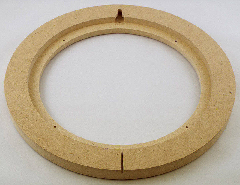
FIGURE 8. Wooden frame.
I decided to use MDF because it’s easily cut to shape and paints very nicely. I thought about using real wood, but the problem is that the frame would be extremely fragile where the grain goes across the frame.
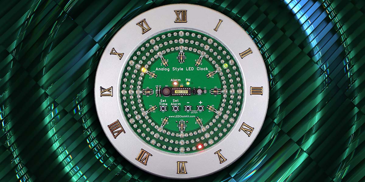
I painted the frame and applied some clock numbers to it that I got from Hobby Lobby. I mounted the PCB to the frame and now I have a very geeky clock (Figure 9).
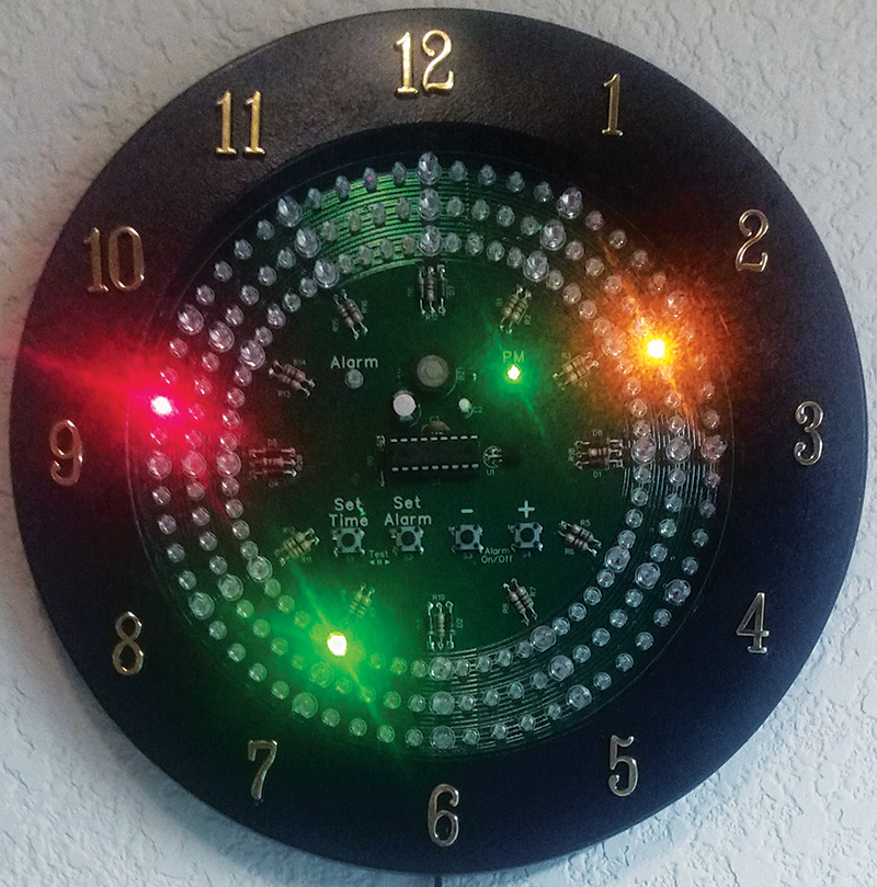
FIGURE 9. Completed analog style LED clock (displaying the time 7:11:47 PM).
Conclusion
I made some changes to the clock after my class was over. I rerouted the PCB so the correct I/O lines are used for the buzzer and LEDs, and I added the capability to use the clock on a 50 Hz electrical system to the code. Now, the clock will automatically detect if the AC line is 50 or 60 Hz and adjust its timing accordingly.
If you decide to take the time to make this clock yourself, when you’re done, you can proudly display your handiwork on your wall and enjoy it for years to come. NV
Parts List
| QTY |
REF DES |
SOURCE |
SOURCE PART # |
MANUFACTURER |
MFR.’S PART # |
DESCRIPTION |
| 1 |
|
Jameco |
100061 |
Jameco Reliapro |
ACU090050A4542 |
AC/AC Wall Transformer, 9 VAC |
| 1 |
J1 |
Jameco |
2114600 |
Jameco Valuepro |
6FT#245.5X2.1 |
Cable Assembly, 2.1 mm x 5.5 mm |
| 1 |
BZ1 |
Digi-Key |
668-1465-ND |
PUI Audio |
AT-1220-TT-11-R |
Transducer, 2.048 kHz |
| 1 |
C1 |
Digi-Key |
493-14503-ND |
Nichicon |
UMA1E101MDD |
Electrolytic Capacitor, 100 µF |
| 1 |
C2 |
Digi-Key |
493-5954-ND |
Nichicon |
UMA1H010MDD |
Electrolytic Capacitor, 1 µF |
| 1 |
C3 |
Digi-Key |
478-4852-ND |
AVX |
SR155C103KAR |
Ceramic Capacitor, 0.01 µF |
| 10 |
D1-10 |
Digi-Key |
1N4001-TPMSCT-ND |
Micro Commercial Co |
1N4001-TP |
Diode, 1N4001 |
| 12 |
DHxx |
Digi-Key |
160-1687-ND |
Lite-On |
LTL2R3KYK |
LED, Yellow, 5 mm |
| 49 |
DHxx, DA0x |
Digi-Key |
160-1664-ND |
Lite-On |
LTL1CHKYKNN |
LED, Yellow, 3 mm |
| 12 |
DMxx |
Digi-Key |
160-1947-ND |
Lite-On |
LTL2R3KGKNN |
LED, Green, 5 mm |
| 48 |
DMxx |
Digi-Key |
160-1659-ND |
Lite-On |
LTL1CHKGKNN |
LED, Green, 3 mm |
| 12 |
DSxx |
Digi-Key |
160-1682-ND |
Lite-On |
LTL2R3KEK |
LED, Red, 5 mm |
| 49 |
DSxx, DA0x |
Digi-Key |
160-1661-ND |
Lite-On |
LTL1CHKRKNN |
LED, Red, 3 mm |
| 16 |
R1-16 |
Digi-Key |
10KQBK-ND |
Yageo |
CFR-25JB-52-10K |
Carbon Film Resistor, 75 ohms |
| 4 |
R17-20 |
Digi-Key |
75QBK-ND |
Yageo |
CFR-25JB-52-75R |
Carbon Film Resistor, 10K ohms |
| 4 |
S1-4 |
Digi-Key |
450-1650-ND |
TE Connectivity |
FSM4JH |
Pushbuttons |
| 1 |
U1 |
Digi-Key |
497-16173-1-ND |
STMicroelectronics |
L78L05ACZ-AP |
Voltage Regulator, TO-92, +5V |
| 1 |
U2 Socket |
Digi-Key |
ED3047-5-ND |
On Shore Technology |
ED18DT |
IC DIP Socket |
| 1 |
U2 |
Digi-Key |
PIC16F628A-I/P-ND |
Microchip |
PIC16F628A-I/P |
Eight-bit Microcontroller |
Resources
Digi-Key
www.digikey.com
Parts source for most of the components.
Jameco Electronics
www.jameco.com
Additional parts source.
Microchip
www.microchip.com
Manufacturer of the microcontroller used for the clock. Of particular interest is their Charlieplexing application note TP029 (www.microchip.com/wwwAppNotes/AppNotes.aspx?appnote=en011636) and their free MPLAB IDE (www.microchip.com/mplab/mplab-x-ide).
DipTrace
www.diptrace.com
Schematic and printed circuit board design software. Free version support up to 300 pins and two signal layers for non-profit use, or 500 pins and two signal layers for academic use.
Bay Area Circuits
www.bayareacircuits.com
Manufactures printed circuit boards. They had a student special that allowed me to make the board for my clock for only $30 at the time.
FNET/GridEye
fnetpublic.utk.edu
Real-time monitoring of electric grid frequency from around the world.
Wikipedia — "Utility Frequency"
en.wikipedia.org/wiki/Utility_frequency
This article has a lot of information about the 50 or 60 Hz frequency used by the utility companies. Of particular interest is the section on Stability.
I would like to thank the following people who were a great help in making the Analog-Style LED Clock a huge success:
- Keith Bayern
- Professor John Hackworth
- Dennis Halverson
- Joel & Jeanne Morrison
PCB files and a kit are available from the Nuts & Volts webstore here.
This kit would be ideal for someone wanting to practice their soldering skills. There are a lot of parts, but they are all through-hole and easy to solder.
Downloads
What’s in the zip?
PCB Files
Code