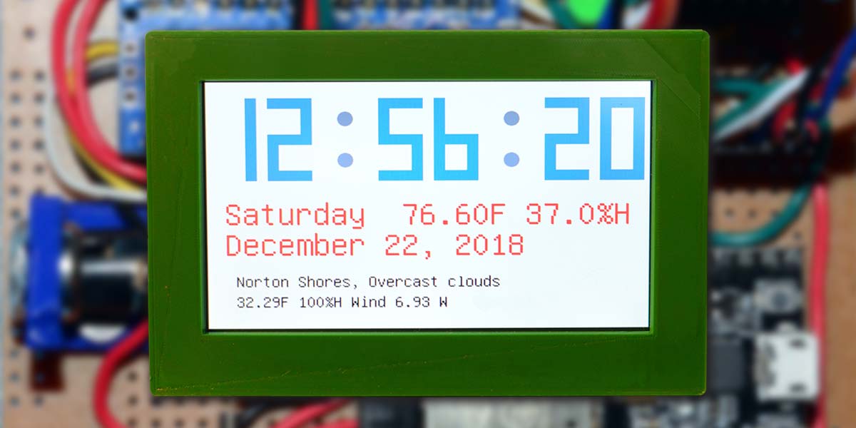
It’s time to build this digital clock that connects via Wi-Fi to the Internet to not only display the usual time, date, temperature, and humidity, but to also be able to retrieve things from the Internet like the weather or weather forecast, and stock market reports as well.
Introduction
I’ve been building digital clocks for longer than I want to admit. My first one was built with over 20 of the 7400 series ICs and the (then) new seven-segment LED displays from Monsanto. My family was really impressed — especially when all those zeros rolled around at the beginning of each hour. Next came a series made with dedicated digital clock ICs that scanned the seven-segment displays. This reduced the IC count considerably and added switching transistors to handle the current.
More recently, I’ve built digital clocks using the Arduino family of microcontrollers and the highly accurate (about one minute per year) real time clock ICs like the DS3234 and DS3231. These allow for a calendar as well as the time, and by adding something like the BME280 you can easily add temperature, humidity, and barometric pressure to an eight-digit seven-segment display. The DS3231 is now available on a nice little breakout board with built-in battery backup and an easy I2C interface.
Setting the correct time has always been a bit of an issue. My early approach was the use of switches. My latest versions have added an IR receiver, which allows you to change the hours or minutes as needed for Daylight Savings Time. A simple pushbutton “clicker” is used with the IR receiver to change the settings. Loss of power with the backup battery (or a dead one) still means reprogramming and uploading the software to the microcontroller.
When initially programming the starting time in the DS3231, once the correct time has been established in the running DS3231, the program is run again with the set time function commented out. The battery will now hold the correct time, even if power is removed.
The advent of the ESP32 Wi-Fi development boards allows for a further increase in the sophistication of a digital clock. It doesn’t take much imagination to envision a digital clock with a large LCD display to not only show the usual time, date, temperature, and humidity, but to also be able to retrieve things from the Internet like the weather or weather forecast and stock market reports as well.
Why the time? With the time retrieved from the Internet, your clock will always be accurate to about the second. In addition, you’ll never need to reset the clock with Daylight Savings Time changes. Retrieving the time from the Internet will do that for you.
My design started with looking into the large seven inch LCD displays with 800x480 pixels. Between eBay, Amazon, and other dealers, there are lots of choices. I liked the price of a number on eBay coming from China but was unsure of just what software would be needed to run them. These have a nice set of mounting holes in the corners. It also appeared that many of them were built to plug into an Arduino Mega 2650 and my thinking was to use an ESP32.
I chose instead to use an Adafruit seven inch 800x480 display connected to their RA8875 driver board. Unfortunately, the Adafruit display doesn’t have any mounting holes, so it will take some extra effort to mount it in a box. Basically, you have a piece of glass, so you’ll need to make a frame of some sort to mount it in.
I knew the RA8875 would run off an Arduino and Adafruit’s software packages have always worked for me. The RA8875 has an SPI interface and the ESP32 has the SPI interface as well, so what could be easier? Famous last words! I couldn’t get the RA8875 to work with my ESP32. I purchased my ESP32 from Amazon — their HiLetgo ESP-WROOM-32 ESP32 development board with 2.4 GHz dual-mode Wi-Fi.
I found this ESP32 easy to use. A good ESP32 Arduino IDE (integrated development environment) installation guide can be found at https://randomnerdtutorials.com/installing-the-esp32-board-in-arduino-ide-windows-instructions and there are others that are easy to find with Google. After several posts on the Adafruit forum asking for help using the RA8875 with an ESP32, Adafruit responded with the message “we’ve never tried the ESP32 w/RA8875 — ESP32 also has all sorts of weirdness that makes it unstable and hard to use.”
Well, I didn’t find the ESP32 hard to use. In an hour or two, I had mine installed on the Arduino IDE, and retrieving time and weather information over Wi-Fi.
After digging into the RA8875 software, I found that on initialization of the SPI interface, it begins by reading a register and checking the return value. If that value doesn’t match what an Arduino returns, it simply quits. I did open an issue with the RA8875 library and hopefully Adafruit will address the problem. I also tested a Teensy 3.1 with the RA8875 and it worked fine.
So, what to do? My display won’t work with an ESP32. My answer was to put a slave Arduino Nano between the ESP32 and the RA8875. A bit of overkill, and a real hassle to form strings on the ESP32 and then send them to the Arduino Nano where it needs to parse them and then send the required commands to the RA8875, but this method does work.
Figure 1 is a block diagram of the circuit I built. The Arduino Nano does most of the work. It drives the LCD display and reads the DS3231 real time clock as well as the BME280 for temperature and humidity.
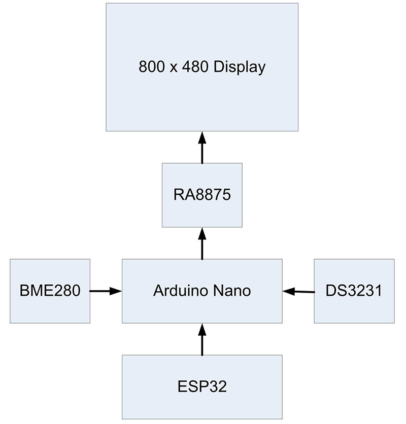
FIGURE 1. Block diagram of the digital clock.
Construction
I used point-to-point wiring on a 3.75 x 2.25 inch prototype board. It fit everything quite nicely. I used a four-pin header to connect the small BME280 breakout board via an eight inch jumper. This keeps the temperature and humidity sensor away from the heat generated by the prototype board.
A pair of six-pin headers with jumper cables connects the prototype board to the RA8875. A nine volt/one amp wall wart type power supply was used which connects to the board through a mating jack. The nine volt power supply is delivering about 200 milliamps to the board.
The usual 7805 five volt regulator supplies five volts to all five small boards: the Arduino Nano; ESP32; DS3231; BME280; and the RA8875 with its LCD display. A small 1 x 1.25 inch heatsink on the 7805 works well. It’s warm to the touch, but not so hot that you can’t keep your fingers on it (which is my seat-of-the-pants measurement for judging the size of a heatsink). The complete schematic is shown in Figure 2.
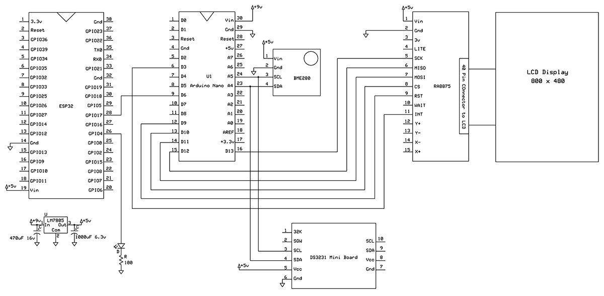
FIGURE 2. Schematic of the prototype.
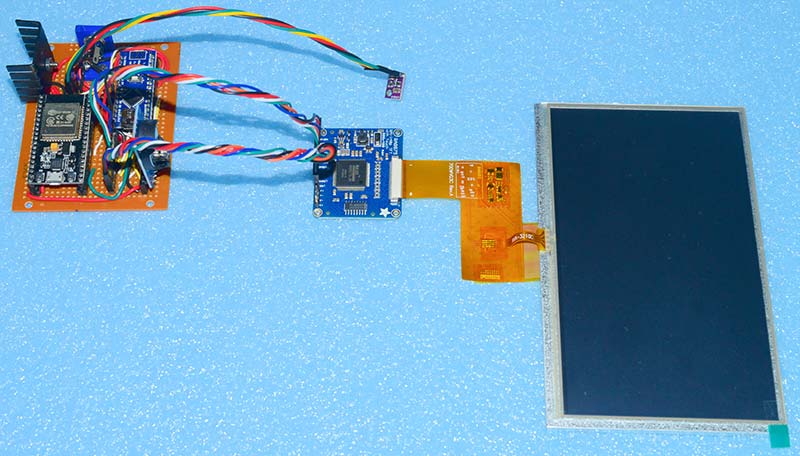
FIGURE 3. The complete prototype.
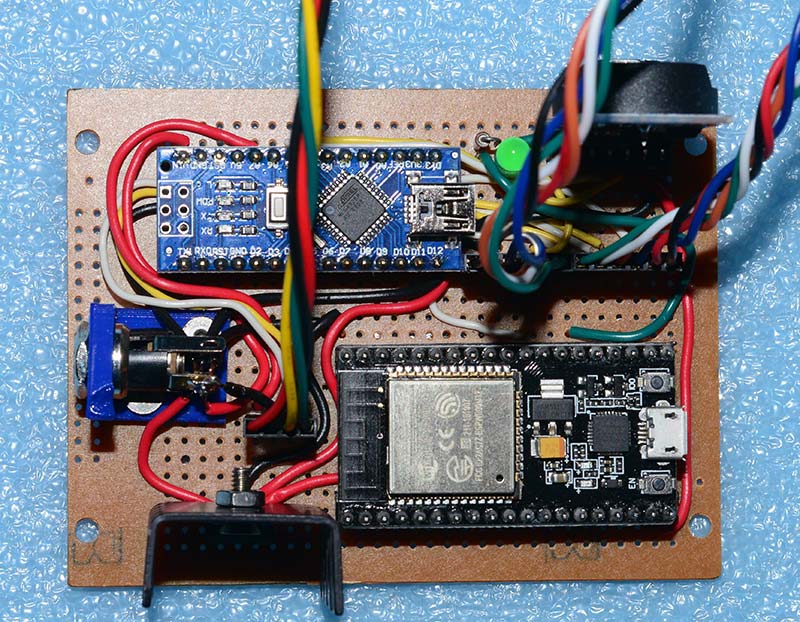
FIGURE 4. Prototype board with components.
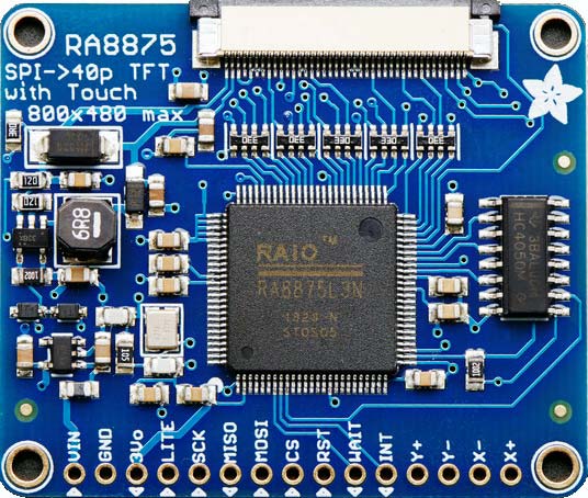
FIGURE 5. RA8875 board.
Software
The heart of this project is the software, given that the hardware is mostly a set of breakout boards that are simply connected together.
There are several specific libraries that will need to be added into your Arduino libraries folder. Check the various #include statements to identify these libraries in the programs provided in the download area for this article. These libraries were found online in various locations and Googling the name will lead you to their sources. The specific locations can change with time. If you need help with installing libraries, go to https://www.arduino.cc/en/Guide/Libraries.
Two programs were written: one for the Arduino Nano acting as the slave; and another for the ESP32 which only is used to connect to the Internet and retrieve the time and outside weather, then pass it on to the Nano. The BME280 board collects the inside temperature and humidity.
The ESP32 software accesses two servers over the Internet: pool.ntp.org (Network Time Protocol) to get the current time; and openweathermap.org to obtain weather information. (See www.ntppool.org/en for more information.)
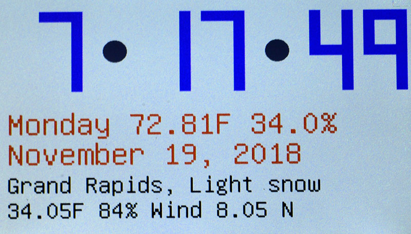
FIGURE 6. The LCD output.
Using pool.ntp.org is pretty straightforward. You’ll need to sign up for access to the openweathermap.org server. Both of these are free services and both sites supply information on how to use their service.
The NTP server will give you the current time to the second whenever polled. The free openweathermap.org server can be polled once a second, but be advised the service only updates the weather information once in less than two hours. It appears this time varies. My software polled these two servers once every 10 seconds. This was done for testing, and polling once every 10 minutes is adequate.
The flowchart of the ESP32 software in Figure 7 outlines the basic operations. The program first connects to the Internet via Wi-Fi. Your local Wi-Fi SSID name and password must be inserted into the program, so it will connect to your specific Wi-Fi. If the Wi-Fi signal is lost for any reason, the program will detect this and then attempt to reconnect.

FIGURE 7. Flowchart of the ESP32 software.
After connecting to Wi-Fi, the program simply reads the time and weather data from the servers and then sends the information in two separate strings out the Serial2 port to the Arduino Nano. The blue LED on pin 2 of the ESP32 will light when Wi-Fi is connected and go out if Wi-Fi is lost. The green LED (mounted separately on the board) will go on for one second when the Serial2 port sends its strings. After the green LED is turned off, the program delays for nine seconds and then loops.
When connecting to the pool.ntp.org server, your offset in seconds from GMT (Greenwich Mean Time) is specified along with the Daylight Savings Time offset in seconds. For the weather, there are different ways to specify what weather location you wish the openweathermap.org server to report.
I choose using a zip code and specifying imperial measurement, which then reports the temperature in Fahrenheit. You can refer to the software in the download area for more details. The ESP32 software has been tested on the ESP-WROOM-32 development board and the AZDelivery ESP32 Nodemcu CP2102 module WLAN Wi-Fi development board — both available on Amazon. It was also tested on the original ESP32 DevKitC board. Only the HiLetgo board has the blue LED tied to pin 2.
Figure 8 illustrates the flowchart of the Arduino Nano software. It not only receives the data strings from the ESP32, but it also hosts a DS3231 real time clock circuit and a BME280 temperature/humidity/pressure circuit along with the RA8875 board to drive the LCD.
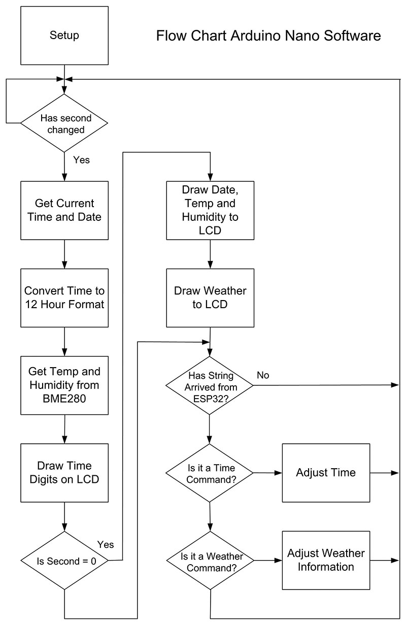
FIGURE 8. Flowchart of the Arduino Nano software.
While the DS3231 circuit keeps the time quite accurately, it is reset once every 10 seconds to maintain its accuracy and to automatically adjust to Daylight Savings Time. How often we reset the time and update the weather is determined by the program running on the ESP32.
The Nano resets things whenever it receives a string from the ESP32. The BME280 operates independently and gives the temperature and humidity at a location close to the circuit board, i.e., the inside temperature and humidity. The outside temperature, humidity, and conditions are obtained from the Internet when a weather string is received by the Nano from the ESP32.
I wanted the time to be displayed in large numbers that could be seen across a room. The Adafruit software library for the RA8875 is quite limited when it comes to outputting text, so I wrote my own function to draw large 80x160 pixel seven-segment numbers.
Parts List
- Adafruit RA8875 and seven inch 800x480 pixel LCD display
- HiLetgo ESP-WROOM-32 ESP32 ESP-32S development board
- Arduino Nano
- DS3231 breakout board with battery
- BME280 breakout board
- Header pins
- Header jumpers
- 5.5 x 2.1 mm jack
- Nine volt/one amp wall wart type power supply
- LM7805 five volt regulator
- Heatsink for LM7805
- Green LED
- 100 ohm resistor
- 3.75 x 2.25 inch prototype board
- Wire, solder, screw, nuts
One needs to remember that each time a number is drawn, you need to clear the area underneath it or else the drawings pile on top of each other. I felt the text output was difficult to read at any distance even with the larger fonts on the RA8875. I thickened the font after drawing it once by drawing it again with a location one pixel over and down from the first location. A filled circle in deep yellow for a.m. and dark gray for p.m. separates the hours, minutes, and seconds.
While I like the I2C interface on the DS3231 board, the RTClib (real time clock library) that uses this interface has a feature I don’t like. It’s set up to only produce a 24 hour clock. Most digital clocks use the 12 hour mode, so you need to check for a zero hour and hours larger than 12 and adjust the hour accordingly.
The DS3231 registers do allow for both 12 and 24 hour clocks. In addition, the RTClib does not write to the day of the week register in the DS3231; instead it uses its own algorithm to calculate the day of the week.
I prep the time in the DS3231 by setting the current time and date using ).rtc.adjust(DateTime(year, month, day, hour, minute, second)). Once the DS3231 is running with the correct time, I then comment out this line and compile and upload the program again. The battery on the DS3231 board will now keep the clock running when power is removed, and when the program restarts, it won’t set the time but simply continue reading it from the DS3231. Both programs are available in the download material.
I enjoyed putting this digital clock together. Now, all I need to do is to design a “proper” box to mount it in. NV
Downloads
What’s in the zip?
Source Code