In my previous Nuts & Volts Theremin article (see Resources), I described the first of my laser Theremin projects: the LASERVox. This is a simple-to-construct Theremin-like device that acts as a MIDI controller for a synthesizer. In that article, I discussed the possibility of a more analog style laser Theremin that has its own built-in synthesizer or pitch generator. That’s the topic of this article! We’ll build the FLiPVox: a continuous pitch laser Theremin with its own mini synthesizer.
Before we get into the FLiPVox, I should explain what a Theremin is, for any of you who haven’t come across one before. I gave quite a detailed description of the Theremin in my first article, but for those of you who haven’t read it yet, here are the key facts.
The Theremin, invented by Russian physicist Leon Theremin in 1920, is the only musical instrument that you play without touching it. It’s also one of the first electronic musical instruments, and it’s one of the most responsive and sensitive electronic musical instruments ever built.
The Theremin has two antennae: one to control the pitch and the other to control the volume. Essentially, the capacitance of the musician’s hand (and to a lesser extent whole body) when situated in the pitch and volume fields around the antennae modify the frequency of the instrument’s oscillators, and this is used to generate a tone and control the volume of that tone.
You play the Theremin by controlling the pitch with your right hand and the volume with your left hand. The closer your right hand is to the pitch antenna, the higher the pitch. The closer your left hand is to the volume antenna, the lower the volume. You can find many more details (including a block diagram of a Theremin) in my previous LASERVox article.
In my laser Theremin projects, the antennae are replaced by Parallax LaserPING infrared laser time-of-flight distance sensors. This approach trades off the exquisite sensitivity of a Theremin against robustness, simplicity, and ease of construction. Nevertheless, the laser Theremin are real musical instruments and are quite playable. Note that I’m always careful to distinguish between Theremin and laser Theremin, because they are very different even though they are played in a similar way.
The LASERVox is a MIDI controller, so its output is pitch quantized because MIDI is pitch quantized. It’s certainly possible to make a MIDI Theremin that offers a continuous sweep of pitch by creative use of MIDI pitch bend, but I think this is not really feasible for a Nuts & Volts project because it depends entirely on the MIDI implementation of the synthesizer that is being controlled. It would work fine on some synthesizers but not on others, and that would be very frustrating indeed.
How then, do we build a continuous pitch laser Theremin? The approach I’ve taken here with the FLiPVox is to use the Parallax Propeller chip as the controller for the pitch and volume sensors and as a simple synthesizer. As we will see, the Propeller chip makes a surprisingly good synthesizer thanks to the sheer power and elegance of the multi-core Propeller chip combined with some excellent C libraries.
I discussed the Propeller chip in some detail in a different Nuts & Volts article (see Resources), and I refer you to that article for more details about this wonderful chip. However, the short story is that the Propeller has eight independent cores, which is a bit like having eight microcontrollers to work with at once. These share data via a common hub that offers each core in turn sole access to the core resources for one clock cycle.
This is why it’s called the “Propeller.” You can think of the hub rotating around each of the cores, offering each of them access to its resources in turn. Provided a core can do what it needs to do with a resource in one clock cycle, there’s no possibility of cores “stepping on each other and possibly overwriting each other’s work.
When an operation takes more than one clock cycle, there’s an elegant locking mechanism that allows a core to lock a resource for sole access (I used this to good advantage in the LASERVox project). This makes multi-core development simple, and you’ll find that you can do things quite easily with a multi-core that would be prohibitively difficult with a single core.
We’ll see later that as well as having eight cores, the Propeller chip has two counter modules per core, meaning that each core can be running up to three parallel processes, making a total of 24 parallel processes for the chip. That’s pretty mind blowing!
In this project, we’ll use the Propeller FLiP board. This is a development board that gives you a Propeller chip and all the necessary support circuitry in a 40-pin breadboard-friendly package.
If you haven’t used the Propeller or a FLiP before, you are in for a treat because you’re about to encounter an astonishingly powerful device that is robust, easy, and fun to use. The FLiP is my go-to board for all but the simplest projects.
How the FLiPVox works
Figure 1 shows a block diagram of the FLiPVox and Figure 2 shows the circuit diagram.
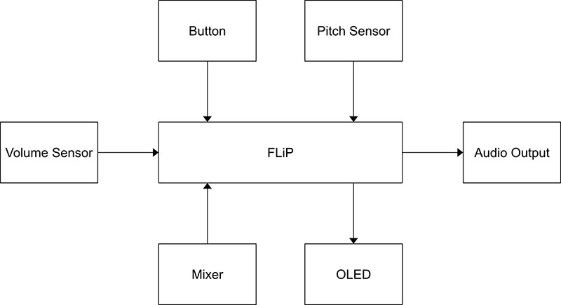
FIGURE 1. FLiPVox block diagram.
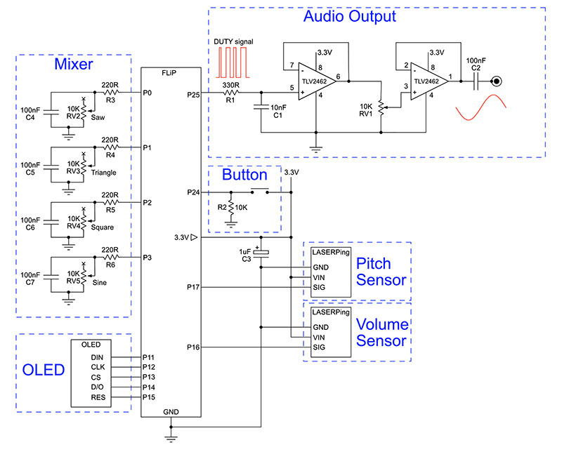
FIGURE 2. The FLiPVox circuit diagram.
The FLiP board accepts inputs from the Pitch Sensor, Volume Sensor, Mixer, and Button, and outputs to the OLED (to indicate the pitch) and to the Audio Output that plays a tone at a pitch and volume determined by the Pitch Sensor and Volume Sensor, respectively.
The timbre is determined by the Mixer, which controls the mixing together of sine, square, triangle, and saw waveforms. The Button simply allows the selection of one of three pitch ranges for the instrument.
In the rest of this article, I’ll take you on a detailed tour of each of these blocks, explain how they work, and how to construct them. However, before we get into the electronics and coding, we’ll set up the development environment.
Setting Up the Development Environment
First, you need to download and install the SimpleIDE development environment from Parallax (see Resources). You’ll find installers and instructions for Windows, Mac, Linux, and Raspberry Pi.
Once you have the software installed and running, you should see a window like the one in Figure 3.
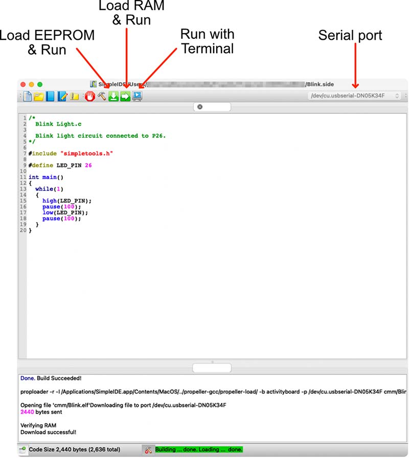
FIGURE 3. Parallax SimpleIDE.
SimpleIDE is project based, so to do anything with it you have to create or load a project. You can manipulate projects from the toolbar (the first five buttons) or from the menus. There are five key things to note about SimpleIDE:
- The serial port dropdown. This is where you select the serial port that your FLiP is connected to. You can’t load software to the FLiP unless the right serial port is selected. On the Mac, this is usually trivial because there’s typically only one entry in the list. On other platforms, there may be several to select from. The dropdown may be empty until you plug in a FLiP! If you power cycle your FLiP by disconnecting the micro-USB, you’ll have to select the serial port again.
- Load to RAM & Run. This is the normal option during development and testing. It compiles your code and loads it to the FLiP RAM. This is a very quick process, but if you power cycle the FLiP, the code will be lost.
- Load EEPROM & Run. This is the option when you have finalized your code. It’s compiled and loaded into the FLiP EEPROM where it is persistent. This takes a bit longer than Load to RAM & Run because it’s writing to EEPROM. When the FLiP is power cycled, it will boot to this code.
- Run with Terminal. This is exactly the same as Load to RAM & Run, except that it opens the SimpleIDE terminal. You can print to this from within your C programs. Note that the terminal window has a nasty habit of popping up under existing windows! You may need to search for it.
- Getting help. SimpleIDE has a comprehensive help system under the Help menu. In particular, you should take a look at the SimpleIDE User Guide, the Propeller C tutorials, and the Simple Library Reference. The Simple Library is where you can find all the Propeller C code for working with serial ports, peripherals, etc.
Once you have some familiarity with SimpleIDE, the next step is to download the FLiPVox code from the article downloads. Unzip the file into a convenient directory. You’ll find that there are several projects in the zip file, and we’ll use all of them as we develop the FLiPVox.
Testing the Development Environment
We can now test the development environment.
- Plug the FLiP into the bottom of a full-size solderless breadboard (see Figure 4) and connect it via its micro-USB to your computer via a USB hub for safety. A green LED next to the power symbol (above P8) should light up telling you that your FLiP is ready to go.
- Ensure the serial port for the FLiP is visible and selected in SimpleIDE. If you have problems making a serial connection, it might be your micro-USB cable. Some cables are designed for charging only and don’t have a full complement of wires for data transfer. There’s no easy way to tell the difference apart from trial and error.
- In SimpleIDE, select the menu Project/Open or use the toolbar, and open Blink.side from your FLiPVox code directory. The FLiP board has a built-in LED connected to pin 26. Download the code to the FLiP RAM, and you should see the LED blink.
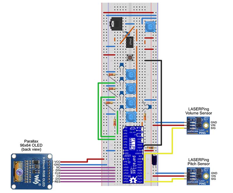
FIGURE 4. Example breadboard layout for the FLiPVox.
If everything works, we are good to go! If not, check that everything is plugged in and that you have selected the right serial port. SimpleIDE should warn you if there are any problems. You might try modifying the blink time in the code just to get a bit more used to SimpleIDE.
Mechanical Construction of the FLiPVox
Before you do anything else, you should ensure that the breadboard, LaserPING sensors, and OLED screen are securely mounted. There’s quite a lot of off-board wiring, and a loose connection to the breadboard can cause you no end of problems.
Mechanically, my FLiPVox is constructed in pretty much the same way as my LASERVox. You can see a photo of the FLiPVox in Figure 5. It’s a reverse L shaped instrument comprising a solderless breadboard with miscellaneous components, an OLED screen, and two LaserPING distance sensors.
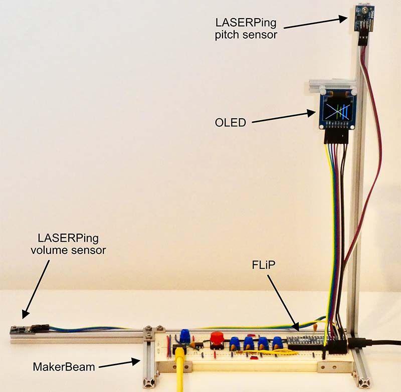
FIGURE 5. The FLiPVox MakerBeam construction.
It’s constructed in a standard Theremin configuration with the pitch sensor on the right where the pitch antenna would be, and the volume sensor on the left where the volume antenna would be.
I used MakerBeam (see Resources) to create a reverse L shaped frame. I attached the components to that as shown in the figure. The volume LaserPING sensor is mounted in the horizontal plane about 20 to 30 cm to the left of the pitch sensor, which is mounted in the vertical plane about 20 to 30 cm above it. The OLED screen should be mounted as close to the pitch sensor as possible.
On my device, the OLED is actually a bit lower than I would like because I was constrained by the length of the only eight-way male-to-female DuPont cable that I happened to have available.
Of course, you don’t have to use MakerBeam. You can use a frame made of wood or some other material. It really doesn’t matter as long as the breadboard, pitch sensors, and OLED screen are well secured so that you don’t have problems with the wiring.
Constructing the Electronics
The circuit is quite simple and can be easily built on a solderless breadboard. There is a suggested breadboard layout in Figure 4. I strongly suggest that you build the FLiPVox block by block, testing each block as you go.
Not only will this ensure that you get a working device, it will also allow you to understand the rather complex FLiPVox operating software by getting familiar with the much simpler test programs.
You can power the FLiPVox via the micro-USB port, or by connecting a 9V battery or 5V to 9V power supply to FLiP GND and ▷5-9V pins. If you choose to use a 5V micro-USB power supply, make sure that it’s a micro-USB power supply and not a micro-USB charger! This is because chargers have complex circuitry to manage the power to the devices they’re charging, and the FLiP sometimes doesn’t play well with them.
OLED
We’ll start by wiring up the OLED screen because it will be very handy for calibration and testing.
The FLiPVox uses a Parallax 96x64 Color OLED module that communicates with the FLiP via a five-wire SPI (Serial Peripheral Interface). Propeller C has a library to drive this display, so it’s simple to use.
Connect the OLED to your breadboard as shown in the circuit diagram (Figure 2) and breadboard layout (Figure 4) using an eight-way male-to-female DuPont cable. You can buy these cables in wide ribbons in various lengths, and you just tear off the number of cables you want. They’re great for breadboard work, and I never seem to have enough on hand.
Load the project OLEDTest.side and hit the Load RAM & Run button in SimpleIDE. You should see a bouncing ball that draws a Celtic knot on the screen. If not:
- Check you have power to the OLED.
- Check that the OLED pins are wired up correctly according to Table 1.
| FLiP Pin |
OLED Pin |
| P11 |
DIN |
| P12 |
CLK |
| P13 |
CS |
| P14 |
D/0 |
| P15 |
RES |
TABLE 1. OLED wiring.
Now that we have the OLED working, we can use this in the rest of our test programs.
Button
Wire up the single pushbutton as shown in the circuit diagram and breadboard layout. We’ll use this button to select pitch ranges for the FLiPVox.
Load ButtonTest.side and select Load to RAM & Run. The OLED should display one of the three pitch ranges every time you press the button.
Mixer
The Mixer block comprises four 10K potentiometers and some associated 220R resistors and 100 nF capacitors. These pots don’t mix the signal directly. Rather, we digitize the voltages across them and use these values to determine the relative amounts of sine, square, triangle, and saw waveforms the software adds to the final audio output mix of the FLiPVox. We’ll see shortly how we turn the analog voltage at the pot wipers into a number using the resistors and capacitors.
Connect up the pots and their associated resistors and capacitors according to the circuit diagram (Figure 2) and the breadboard layout (Figure 4). Make sure the wipers of the pots go to the correct FLiP pins.
Looking at the circuit diagram, you can see that each pot is used as a variable resistor. There is a 100 nF capacitor connected between the wiper and GND. The wiper is also connected via a 220R resistor to a FLiP pin. The other terminal of the pot is not used.
We can measure the value of the pots as follows (see the sidebar for more details):
- Set the appropriate FLiP pin to output and make it high.
- Wait for a short time for the capacitor to fully charge.
- Set the pin as input.
- Call rc_time(...) on the pin. This starts a Propeller counter module (see sidebar) that increments while the pin is high and stops when it goes low. It returns the number of clock ticks which is proportional to the value of the pot.
Pulse Modulation and Propeller Counter Modules
You may be wondering how the Propeller chip — which has no analog outputs — can ever be an effective synthesizer. The audio output stage of the FLiPVox must perform a little bit of magic! How does it convert a digital signal to an analog one?
In fact, the strategy for doing this is very simple. Just make an I/O pin transmit a series of pulses and average the voltage on the pin using a simple resistor and capacitor filter as shown in the FLiPVox circuit diagram. The key concept you need to understand how this works is duty cycle (also called duty).
Think of a digital pulse train as a series of repeating on/off signals. The percent duty cycle is:
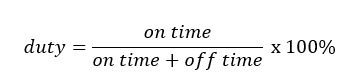
where on time + off time is the period of the pulse wave.
For example, if a FLiP I/O pin transmits a series of 3.3V pulses that are on for half the time, then the duty cycle is 50% and the resulting average voltage is 50% of 3.3V = 1.65V. Similarly, if the pulses are only on for a quarter of the time, the duty cycle is 25% and the average voltage is 25% of 3.3V = 0.825V. If the duty cycle is varied with time, then it’s possible to generate an arbitrary waveform. This is how the FLiPVox generates its tones.
Keep in mind that the average voltage is solely determined by the pulse train’s duty cycle. The actual pulses can be arranged in any way you like (within reason!), provided you don’t alter the overall duty cycle. In fact, there are several standard ways to arrange the pulse train, and we’ll now look at the most common way: Pulse Width Modulation (PWM). This is what most microcontrollers use, and then we’ll see how the Propeller does it.
Virtually all microcontrollers offer digital-to-analog conversion via PWM. In PWM, the pulse train has a fixed period, but the wave is only on for a fraction of that period, so PWM consists of a stream of equally spaced pulses with (potentially) different widths.
For example, if the pulse is on for half the period of the wave, we have a symmetric square wave and the duty cycle is 50%. If it’s on for one tenth of the period, the duty cycle is 10% and we have a very asymmetric pulse wave.
PWM is good for power and motor control but is generally unsuitable for audio generation. This is because many microcontrollers only offer PWM at comparatively low frequencies due to the calculation time it takes to change pulse widths.
For example, the Arduino family defaults to PWM frequencies between 500 Hz and 1 kHz depending on the board. To put this into perspective, C8 is about 4 kHz, so these frequencies are clearly inadequate for audio. This is why when you see Arduinos used in synthesizer circuits as oscillators, they are generally only used as low frequency oscillators (LFOs).
The Propeller sound library doesn’t use PWM; it uses its own unique form of pulse modulation that is much more suitable for audio and very high-speed/high-resolution digital-to-analog conversion. I’ll take some time to look at this here because it introduces an important Propeller feature — counter modules — that I haven’t described in any of my previous articles.
The Propeller chip has two counter modules per core. These are complex state machines that run independently of the core and which are used for all kinds of pulse generation and measurement activities. Because they run independently of the core, this means that each core can execute up to three parallel processes: one process for the core, and one process for each of the counter modules.
Generally speaking, a core sets a counter module a task, such as pulse generation, and goes away and does something else, leaving the counter module to get on with it.
Each counter module has three 32-bit registers:
- PHS (Phase) – Accumulates a sum by having FRQ conditionally added to it on specified clock cycles.
- FRQ (Frequency) – The amount added to PHS on a clock cycle.
- CTR (Control) – Specifies the conditions under which FREQ is added to PHS. Also controls the assignment of up to two pins to the counter module.
On every clock tick, the counter module uses CTR (and possibly the state of the pins) to determine whether FRQ is added to PHS. This simple mechanism gives rise to very rich behavior, and there are 32 possible counter module modes described in in the Propeller documentation (see Resources).
To generate audio, the sound library uses a counter in “DUTY differential” mode. I will refer to this simply as DUTY mode for brevity.
In DUTY mode, we have the following conditions:
- PHS is initialized to 0.
- On every clock tick, FRQ is added to PHS with a carry, and the carry bit (1 or 0) is output on a Propeller pin. The carry bit is set whenever the PHS register overflows, i.e., PHS + FRQ > 232 - 1.
The key is that the pulsing carry bit is output on a Propeller pin. This is the pulse modulated signal that we turn into an analog voltage by simple RC smoothing!
Unlike PWM, the signal generated by DUTY mode is complex (as we shortly will see), but remember that the arrangement of the pulses doesn’t matter — just their overall duty cycle. In DUTY mode, the duty is given by the following equation:
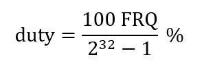
where 232 - 1 is the largest number the 32 bit PHS register can hold before it overflows.
As I said above, the DUTY pulse train is quite complex, and it’s difficult to see on an oscilloscope. However, if you set the scope trigger mode to single and take a few snapshots, you can just about see what is going on.
We can understand DUTY mode more easily by using a simple model with small registers, so we can see precisely what is happening. For this model, we’ll imagine that PHS is only four bits, which means the largest number it can hold before overflowing is 1111 = 24 - 1=15.
Figure A shows DUTY mode in action. The system clock is along the top in the first row. Adding 1 to PHS on each clock tick means there are 15 clock ticks before it overflows and wraps around. This means we only need to consider 15 ticks because then everything repeats.
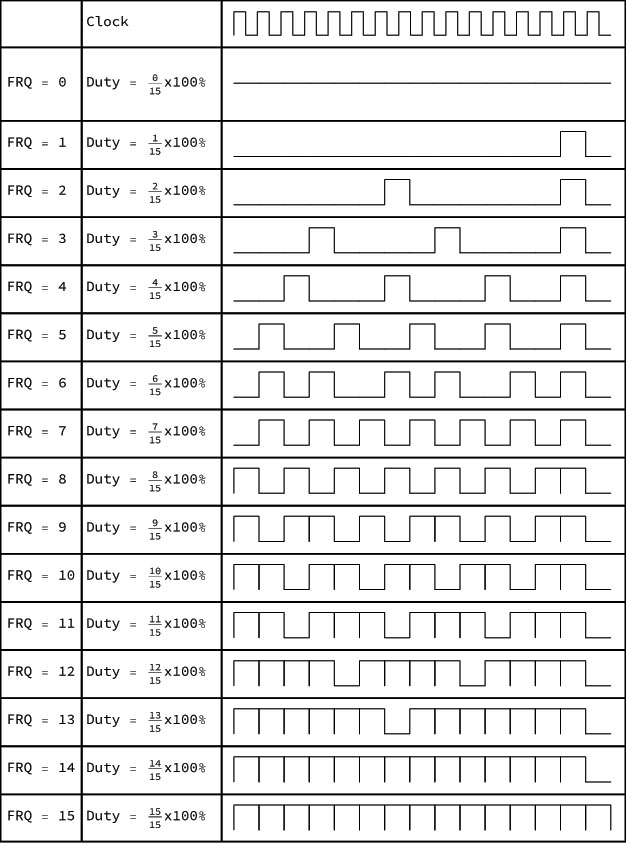
FIGURE A. DUTY mode in operation. FRQ is added to PHS on each clock tick and a carry may or may not result.
Column 1 in the table shows the value of FRQ that is added to PHS on each clock tick. Column 2 shows the duty cycle, and column 3 shows the carry flag waveform. If PHS + FRQ fits in PHS, the carry flag is 0, and if it doesn’t, PHS overflows and the carry flag is set to 1.
With such small registers, you can do the calculation by hand to see when the carry flag is high or low (confession — I used Wolfram Mathematica). Notice that for a cycle of 15 clock ticks, the number of pulses is always equal to FRQ. This allows us to use FRQ to calculate the duty as above.
It’s quite easy to understand the overall structure of the output waveform. When FRQ = 0, adding FRQ to PHS doesn’t change PHS so we never get a carry pulse, and the duty is 0%. When FRQ is small, PHS doesn’t overflow very often, so we get a small number of carry pulses. When FRQ is large, PHS overflows more often, so we get more carry pulses.
Finally, when FRQ = 15, we get a carry pulse on every clock tick, which gives us a duty of 100% — a DC voltage.
DUTY can potentially give you 32 bits of voltage resolution because there are 232 - 1 possible values for FRQ, and each of these corresponds to a voltage level. However, with an 80 MHz clock and assuming you can update FRQ once every clock cycle, it takes (232 - 1)/80000000 = 53 seconds to output this many levels!
Clearly, audio operation can only occur at a significantly lower resolution. It’s easy to calculate that if the maximum desired frequency is 20 kHz (roughly D10), then we can achieve 12-bit resolution if we can update FRQ once every clock tick. However, this isn’t possible because the value for FRQ must either be looked up or calculated for each update.
In practice, I’ve found that the sound library generates reasonable waveforms from about C3 to C7. It’s not Hi-Fi, but it’s good enough for our purposes here because the waveforms sound fine, and that’s all that really matters.
A Propeller counter module is used in a different mode to read the mixer pots. This mode is called “POS Detector” and it works very simply: Add FRQ to PHS on every clock tick that a specified pin is held high. Clearly, if PHS starts at 0 and FRQ is 1, then this mode just counts the number of clock ticks that a pin is held high. It’s a timer.
Consider one of the FLiPVox mixer circuits (say on P0). We obtain a value for the pot in clock ticks as follows:
- Set P0 to high which starts to charge capacitor C4 through R3.
- Pause for a bit to let the capacitor fully charge.
- Call rc_time(...)
a) rc_time(...) sets P0 to input and starts the counter module on P0 in POS detector mode with PHS = 0 and FRQ = 1. The capacitor is charged, so P0 reads high.
b) The capacitor discharges over time through variable resistor RV2. FRQ is added to PHS on every clock tick that P0 remains high.
c) When the voltage across the capacitor has been discharged to < 1.65V, P0 reads low. The counter module detects this and stops, and the number of clock ticks it took for the capacitor to discharge to this level is available in PHS.
d) rc_time(...) returns the value in PHS.
Unlike the sound_freq(...) function that we use for tone generation, the rc_time(...) function is synchronous because it waits for the counter module to finish. That’s fine for many applications. However, remember that the counter module runs independently of the core, so it’s quite possible to write an asynchronous version of rc_time(...) that simply kicks off the counter module and abandons it to do its thing. The core can query PHS when it wants the value.
There are 30 other counter module modes, and most of the pulse generation/timing things you would normally do with a core, you can do better and faster with a counter. I don’t have space to go into all the other counter modes in this article, so I have put some links to useful Propeller documentation in the Resources section.
This procedure only works because when FLiP pins are set as inputs, they behave like high impedance Schmidt triggers, and switch cleanly from high to low when the applied voltage falls below their 1.65V threshold. Each core has two independently running counter modules, and the sidebar explains how rc_time(...) uses one of these to count the number of clock ticks until the pin goes low.
This is a very easy way to read an analog voltage, but it’s not without its disadvantages. There is some non-linearity because the capacitor discharge is non-linear. Also, you don’t get an absolute value. It depends on the rate of discharge which depends on the true capacitance of the particular capacitor you have used.
For best results, the mixer circuit needs to be calibrated. You can do this as follows:
- Load and run the MixerTest.side project. You should see a screen with numbers that change as you rotate the pots. If not, check your wiring!
- Set the pots to maximum (fully to the right). Wait for the OLED to refresh.
- The software measures each pot 1,000 times and writes the lowest value obtained for each pot to the OLED and to the FLiPs EEPROM. This should be a number somewhere between 750 and 850.
- Leaving the pots set to maximum, turn off the power. The calibration value for each pot is now stored in the EEPROM so we can use it in other FLiP programs.
One of the nice things about the FLiP is it has a 64 KB EEPROM on an internal I2C bus. The top 7675 bytes of this are available for you to store data in. In this case, we write the calibration values for each pot into EEPROM and read those values in subsequent programs that use the pots.
Now for a bit of fun! I think it’s a tradition or an old charter or something that if you are of a certain age and have two digitized pots and a screen, you have to make an Etch A Sketch.
Load the demo program EtchASketch.side and draw away. The sine pot controls the X dimension, the square pot the Y, the triangle pot sets the color of the line, and when the saw pot is set over halfway, it clears the screen.
Apart from fun, there is an educational reason for this program. Examine the code to see:
- How the calibration values for the pots are read in from the EEPROM.
- How the measurements taken from the pots are scaled to the appropriate values.
We’ll use both these techniques in the final FLiPVox program.
Audio Output
You’ll need to connect the FLiPVox audio output to an amplifier/speaker combo of some sort, or you can use headphones. A keyboard amplifier (preferably with some onboard effects) is the ideal solution. I use an old Peavey electric guitar amplifier that I happen to have and plug the FLiPVox into the Tape/CD input rather than the guitar input. This gives excellent results. Note that the FLiPVox (or any synthesizer) won’t sound right when plugged into an electric guitar input.
WARNING: Never put headphones on then connect them to a homemade electronic device!
A safe procedure is as follows:
- Turn the FLiPVox output volume pot (RV1) down to 0.
- Turn the sine mixer pot to maximum and all the others to minimum. The sine wave is the smoothest tone and is least likely to damage anything.
- Connect the headphones and hold their speakers close to — but not in — your ear.
- Slowly turn the FLiPVox output volume up until you hear something. The FLiPVox output is mono, so you’ll only hear a sound on one speaker.
Use the same procedure for connecting to an external amplifier. Start with the amplifier and FLiP output volumes at zero and slowly turn them up.
The FLiPVox uses the Propeller sound.h library to generate its tones. This library gives you access to a simple synthesizer that offers a choice of five waveforms (sine, square, triangle, saw, and noise) on four channels that are mixed together and presented as a modulated pulse train on a specified pin (see sidebar). These waveforms are shown in Table 2.
| Waveform |
Channel |
Quality |
|
Sine

|
0 |
A very pure tone with not much character. It’s the fundamental frequency (f) with no harmonics. |
|
Square (50% duty cycle)

|
1 |
Sounds a bit like an organ or Stylophone. Rich sounding with even harmonics (f,2f,4f, ...). |
|
Triangle

|
2 |
Often described as sounding hollow, it’s good for flute sounds. Odd harmonics only (f,3f,5f, ...). |
|
Saw

|
3 |
A powerful buzzy sound good for bass and synth leads. Can be used to create string sounds. All harmonics (f,2f,3f, ...). |
| Noise |
N/A |
Hissing. A random waveform useful for sounds of sea or wind. |
TABLE 2. FLiPVox waveforms.
An early prototype I built ran five of these synthesizers each in its own core and own output pin, so you can see that the Propeller chip is capable of quite impressive sound-generation using this library.
Assemble the Audio Output as shown in the circuit diagram and breadboard layout. This comprises R1, RV1, C1, C2, and the TLV2462 dual operational amplifier. This is the most complex part of the circuit, so you need to check your wiring carefully. The TLV2462 is a high-quality rail-to-rail dual op-amp with a high output drive. It’s very well suited to buffering the output of digital-to-analog converters (DACs) because these generally have outputs that go from GND right up to the positive supply rail. Not all op-amps can handle this, but the TLV2462 can.
As an aside, when you want an op-amp, it’s tempting just to reach into your parts bin for the venerable (and somewhat overused) LM358. It has decent specifications and will work most of the time. However, there are so many great op-amps out there that it’s well worth doing a bit of research to find one that has better characteristics for your particular circuit.
For example, you might need rail-to-rail (as in this case), low input offset voltage, or excellent linearity. There really is no “one size fits all” when it comes to op-amps.
The pulse modulated signal on P25 is smoothed by the low pass filter formed by R1 and C1. The filtered signal is passed into a unity gain non-inverting amplifier (i.e., a buffer) formed by half of the TLV2462. This has a very high input impedance so it doesn’t perturb the filter, and a low output impedance so it can drive an output load.
Potentiometer RV1 provides a simple volume control that feeds into the other half of the TLV2462 which is also wired as a unity gain buffer. The output of this is capacitively coupled to the audio out jack. Capacitive coupling provides a flexible output with zero DC offset.
Once you’ve checked your wiring, load and run SynthesizerTest.side. The program plays a two-octave chromatic scale starting on C4 for each waveform (sine, square, triangle, and saw) and also a composite waveform that is 50% sine and 50% square. The OLED displays the name of each waveform as the scale plays. Notice the unique timbre of each waveform. The 50% sine/50% square is particularly mellow.
If you don’t hear anything:
- Check the output volume pot and turn it up to maximum.
- Check that at least one of the waveform mixer pots is at maximum.
- Check your wiring to the jack socket. The sleeve should be at GND; the signal from the output pot should go to the tip; and if you’re using a stereo jack socket, the ring should be not connected.
- Check the wiring of the filter and amplifier, and that P25 is connected.
Pitch Sensor and Volume Sensor
We’ll deal with these two blocks together because they use the same technology.
As you know, the FLiPVox like the LASERVox is a laser Theremin, so it uses LaserPING infrared time-of-flight distance sensors to stand in for the Theremin pitch and volume antennae.
LaserPINGs are great little components. They send out a pulse of infrared laser light and measure the time-of-flight of the pulse from the sensor to the target and back. They’re incredibly easy to use with the Propeller chip and give distance measurements with 1 mm accuracy at 22 measurements per second. That’s plenty for our purposes here.
Connect up both sensors as shown in the circuit diagram and breadboard layout. There isn’t much that can go wrong here; both sensors are connected to +3.3V and GND. The pitch sensor SIG goes to FLiP P16 and the volume sensor SIG goes to P17.
Load LaserPINGTest.side and select Load RAM & Run. You should see a display showing the distances of your hands from the pitch and volume sensors in various units. The first line is the time-of-flight expressed as a number of Propeller system clock ticks. The second and third lines are the distances rounded to cm and inches, respectively. We get much better resolution with the clock ticks, so that’s the number we use in all the calculations.
You can use this program to help you find the pitch and distance ranges for the FLiPVox that are best for you. Do this by positioning your hand in front of each sensor in turn, and making a note of the clock ticks for the nearest comfortable position and the furthest comfortable position. Table 3 shows you what constants you need to change in the main FLiPVox program to calibrate to the new distances.
| Sensor |
Effect |
Distance of Hand |
FLiPVox Program Value |
Default in Clock Ticks |
| Pitch |
Highest Note |
Closest to Pitch Sensor |
PITCH_MIN_DIST |
500 |
| |
Lowest Note |
Furthest from Pitch Sensor |
PITCH_MAX_DIST |
3500 |
| |
Note Off |
Out of Range |
PITCH_OFF_DIST |
5000 |
| Volume |
Loudest Volume |
Furthest from Volume Sensor |
VOLUME_MAX_DIST |
2000 |
| |
Silence |
Closest to Volume Sensor |
VOLUME_MIN_DIST |
600 |
TABLE 3. FLiPVox distance calibration for pitch and volume.
I have quite intentionally not provided the same sort of calibration procedure as I did for the potentiometers because you’ll find it much easier to just edit the numbers in the FLiPVox main program. Unlike a Theremin, laser Theremin are completely stable once distance is calibrated, so you should never have to recalibrate once you’re happy with the distances. I suggest you start with the defaults, and only make changes once you’ve used the FLiPVox for a bit.
The FLiPVox Software
If you’ve got to this point, then everything should be working and all you need to do is load the FLiPVox software and start playing.
Open FLiPVox.side and select Load RAM & Run. Remember that when you’ve finished any tinkering, Load EEPROM & Run will write the software into the FLiP EEPROM so that it will run it on boot-up.
There isn’t much to say about the operation of the FLiPVox. The pushbutton steps you through the three pitch ranges: G2 to C4, G3 to C5, and G4 to C6. The four mixer pots control the mixing of the sine, square, triangle, and saw waveforms, and the volume pot controls the output volume.
The OLED shows a pitch ruler (Figure 6), that indicates how close you are to a note in the chromatic scale.
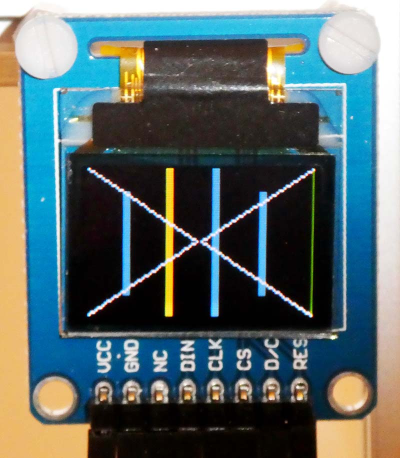
FIGURE 6. The OLED showing the pitch indication ruler. E is yellow.
Long bars indicate natural notes and short bars indicate sharps/flats. All note bars are colored blue, except:
- G and G# are green.
- C and C# are red.
- E is yellow.
Have fun playing with the mixer and creating different timbres. If you can feed the output through an external filter or effects unit, so much the better. I have had good results feeding the FLiPVox output into my Behringer Crave synthesizer.
In the next section, I’ll walk you through how the FLiPVox software works, so that you can make your own modifications.
How the FLiPVox Software Works
We’ll start by considering how the pitch is controlled. The FLiP converts the distance measurement from the Pitch sensor into a frequency that it uses to internally generate sine, square, triangle, and saw waveforms that are mixed together and output as an audio signal. There are two issues that need to be resolved:
- We need to account for the fact that our perception of pitch is logarithmic not linear.
- We need the FLiPVox to behave like a Theremin where the closer the player’s hand is to the pitch sensor, the higher the pitch. This means that pitch is inversely related to distance from the sensor.
Let’s explore Issue 1. Consider the octave As shown in Table 4.
| Note |
Frequency |
Difference in Frequency |
| A2 |
110 Hz |
|
| |
|
110 Hz |
| A3 |
220 Hz |
|
| |
|
220 Hz |
| A4 (Concert A) |
440 Hz |
|
| |
|
440 Hz |
| A4 |
880 Hz |
|
| |
|
880 Hz |
| A5 |
1,760 Hz |
|
TABLE 4. The frequency doubles as a note goes up an octave.
The octave is the only universally accepted consonance. We perceive notes an octave apart as being somehow the same note, but different — one sounds higher than the other. The octave appears to be somehow hard wired into the human perception of pitch, whereas the other consonances appear to be cultural artifacts. That’s why music from other cultures can sound strange or discordant until you’re used to it. We need to understand how the octave is related to frequency in order to successfully create a linear FLiPVox pitch field.
Looking at Table 4, the difference in frequency between pitches A3 and A4 is 220 Hz, which is twice the 110 Hz difference in frequency between A2 and A3. Similarly, the difference in pitches between A5 and A6 is twice the difference between A4 and A5. This means that to go up an octave from a given frequency, we don’t go up by a fixed number of Hz, we have to double the frequency.
Imagine if we convert distance directly into frequency. To go from A2 to A3, we have to move 110 distance units, whereas to go from A4 to A5, we have to go 440 units. The low notes are close together and the high notes are far apart. This is completely unacceptable.
In order to be playable, a Theremin needs to have a linear pitch field where the notes are all the same distance apart. Even the best designed Theremins have some slight non-linearity, but this is very small if the instrument is well designed and correctly set up. Theremin with non-linear pitch fields aren’t really playable, but are okay for fun and special effects.
Let’s look at this logarithmic relationship in a bit more detail, so we can work out what to do about it. We know that the scaling factor for the octave is 2, but what if we only go up a semitone. What’s the scaling factor for that?
In Western 12 Tone Equal Temperament (12TET), the octave is divided into 12 semitones that are considered to be equal; both because they have the same ratio between their frequencies and because they sound equal to our logarithmic perception of pitch. To find this semitone ratio, we simply need the number that — when multiplied by itself 12 times — gives a factor of 2 (the octave).
Clearly, this number is the 12th root of 2, and so the formula to move from a frequency f0 to a frequency fn that is n semitones above it is:
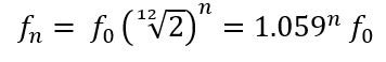
I’ve used a variant of this standard formula many times to calculate the fret positions for guitars and other fretted instruments. You’ll find it everywhere in Western music.
To create a linear pitch field that works the right way around for the FLiPVox (or for any Theremin that uses linear distance sensors), we need to do two things:
- Take the log of the distance. This linearizes the pitch-to-distance relationship because we have log-to-log rather than linear-to-log.
- Invert the distance-to-pitch relationship, so the smaller the distance, the higher the pitch.
We do all this in the software in main(), which runs in core 0. I’ve commented the procedure quite well, so you should have no trouble following it.
The situation is much simpler for the volume control. The FLiP simply converts the distance measurement from the Volume sensor to a number between 0 and 127 that is used to control the master volume of the audio output. The closer the player’s hand is to the volume sensor, the smaller the distance and the lower the volume. So, the relationship is simple and linear, and lets us map distance directly to a number between 0 and 127.
The function getVolume() executes in its own core to continually monitor the Volume sensor and keep the Volume variable up-to-date.
The only other parts of the software are:
- getMix(): Runs in its own core and continually measures the mixer pots. At the start of the function, notice how we read the calibration values for the pots from the EEPROM. If you remember, we put those values in place in the project MixerTest.side.
- getButton(): Runs in its own core and continually monitors the button maintaining a circular counter called scale that can have the value 0, 1, or 2.
There are also a couple normal functions that don’t have their own core:
- setOLED(): Draws the bars on the OLED.
- rom_log(): A fast lookup function for logarithms. The Propeller chip comes with a logarithm table (and a sine table!) in its ROM. This function just reads out the appropriate value represented as an integer. We’re not interested in absolute values, only ratios, so we use this number as-is without bothering to convert it to a floating-point value.
So, that’s it! The software is pretty straightforward — especially if you’ve examined the test programs we created for each component of the FLiPVox.
Playing the FLiPVox
I gave some instructions on playing technique for a Laser Theremin in my previous LASERVox article, so I’m going to focus here on the unique characteristics of the FLiPVox.
Unlike the LASERVox, the FLiPVox is a continuous pitch device. This means that although the hand positions and posture remain the same as for the LASERVox, the playing technique is somewhat different.
With the FLiPVox, you have the huge advantage that you can use your ears as well as your eyes to pitch the notes as you want. This is particularly useful when you’re playing with others because you can slide up to or down to the right pitch if you’re a bit off. With the LASERVox, it’s all or nothing!
One thing you’ll find with the FLiPVox is that the pitch is extremely sensitive to small motions of your hand. This can make it quite hard to play and the sound can be a bit jittery — especially for square and saw waveforms. There’s a simple solution to this problem: reverb!
Reverb has the effect of smoothing out the notes a bit, making the FLiPVox easier and more pleasant to play. It also makes it sound a whole lot better, giving a certain richness to the sound. In fact, you can get a very Theremin-like playing experience when you add a bit of reverb.
You can use a specialized reverb unit or a multi-effects unit, and many amplifiers have some sort of reverb built in nowadays. I use a Korg Kaoss Pad, which gives a decent result. With the reverb on max, the tones become quite ethereal and the instrument is a lot easier to play, having a smoother, more syrupy feel to changing the notes.
In fact, some sort of effects unit is really mandatory for an instrument such as the FLiPVox. Sine, square, triangle, saw, and mixtures of these waveforms quickly become quite tiring on the ear. This is because natural sounds change in timbre over time, and these waveforms don’t. Adding an effect such as reverb can make the simple waveforms move and come alive.
If you have an opportunity to put the FLiPVox output through a multi-effects unit or a synthesizer, then the possibilities are pretty much endless, and you can get some great results. Think of the built-in tones as raw materials that you need to sculpt and shape. This approach will make the FLiPVox a much more dynamic and interesting instrument.
Going Further
There’s a lot of scope for FLiPVox experimentation and tinkering.
At the moment, the FLiPVox has one voice that comprises a mix of sine, square, triangle, and saw waveforms all playing at the same pitch. An easy extension is to make each of the waveforms play at a different pitch. That way, when you mix them together, the FLiPVox plays a chord. You can do this just by modifying the software. The downside of this simple approach is that each of the notes in the chord is a different waveform.
You can improve on this by adding more synthesizers, each controlled by the single mixer. This is generally more satisfactory because each note in the chord will sound the same. The simplest and most flexible way to achieve this is to replicate the Audio Output block on different pins, and then mix all the outputs together using an external mixer. In fact, one of my early prototypes did exactly that.
You can keep adding more synthesizers until you run out of cores! You won’t fit this on a single breadboard, so it might be a good idea to build each audio output stage on a piece of stripboard.
The final level of sophistication is to give each synthesizer its own mixer and audio output. This gives you complete control of the timbre of each pitch in the chord. Each voice requires five pins: four for the mixer and one for the voice.
Again, the best approach would be to build Mixer/Audio Output units on stripboard.
Coming Soon — the FLiPVox CV
In Part 2 of this article, I’ll describe a very simple add-on for the FLiPVox that turns it into a powerful controller for voltage-controlled analog synthesizers. I call this expanded version of the FLiPVox the FLiPVox CV.
As you probably know, analog synthesizers use control voltages (CVs) to control their various components. As well as tones, the FLiPVox CV will output pitch and volume CVs along with a gate signal. You can use the CVs to control any voltage-controlled parameter of an analog synth.
Obviously, for a Theremin, the pitch CV should control a voltage-controlled oscillator (VCO) and the volume CV should control a voltage-controlled amplifier (VCA). However, voltage control is immensely flexible, and the uses of the FLiPVox CV are really only limited by your imagination and the capabilities of your synthesizer.
Analog voltage-controlled synthesizers are now so popular and so cheap, I think that this is a good time to begin to create some projects around them.
Thanks to companies such as Korg, Behringer, and even Moog, you can now get a very credible analog synth for under $200. They often have MIDI as well voltage control, so you get the best of both worlds. I bet a lot of Nuts & Volts readers either have one or are looking for an excuse to get one.
Next issue might encourage you to do so! NV
Parts List
- 1x Parallax FLiP (Parallax SKU 32123)
- 1x Parallax 96x64 Color OLED Display Module (Parallax SKU 28087)
- 2x Parallax LaserPING Sensors (Parallax SKU 28041)
- 1x TLV2464 Op-amp
- 5x Breadboardable 10K Potentiometers
- 4x 220R Resistors
- 1x 10K Resistor
- 1x 330R Resistor
- 5x 10K Breadboardable Potentiometers
- 5x 100 nF Capacitors
- 1x 1 µF Tantalum Capacitor (for decoupling)
- 1x Full Size Solderless Breadboard
- 1x Breadboardable Mono Jack Socket (stereo will also work)
- 1x Tactile Switch
Resources
LASERVox article (Nuts & Volts Issue-3 2020)
Propeller P8X32A Application Note AN001, Counters
https://www1.parallax.com/downloads/an001-propeller-p8x23a-counters
Using Counters in SPIN, PIMORONI Yarr-niversity
https://learn.pimoroni.com/tutorial/propeller-hat/using-counters-in-spin
Propeller Chip Datasheet and Manual (look under Downloads):
https://www.parallax.com/product/propeller-1-chip-44-pin-qfn-chip/#
Propeller Education Kit Labs, Andy Lindsay
https://www.digikey.com/htmldatasheets/production/1766828/0/0/1/Propeller-Ed-Kit-Labs-Fundamentals.pdf
Parallel Processing with the Propeller FLiP, by Jim Arlow
https://www.nutsvolts.com/magazine/article/parallel-processing-with-the-propeller-flip
(Nuts & Volts — 2019 Issue-3 — page 40)
Downloads
What’s in the zip?
All Code Files