Several months ago, an idea popped into my head for a fun project. I wondered if I could burn some characters into the yellow paint of a No. 2 pencil with one of those powerful diode lasers available on eBay. Perhaps it could be my name or my grandkid’s names, or even a happy birthday message to my lovely wife.
THE FINAL RESULT
An hour later and two clicks of the mouse launched my latest brainstorm. I ordered a 1/2 watt blue engraving laser and two galvanometers from China. (Free shipping! Such a deal!)
Figure 1 shows the final result which I’ll describe in the rest of this article. The only problem right now is that all the grandkids want their own customized pencils. Not just yellow ones, but all kinds of screwy colored pencils. I think I opened Pandora’s box.
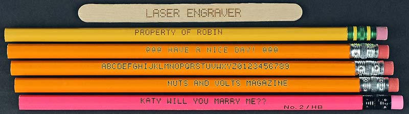
FIGURE 1: Examples of fun messages you can engrave on No.2 pencils and popsicle sticks.
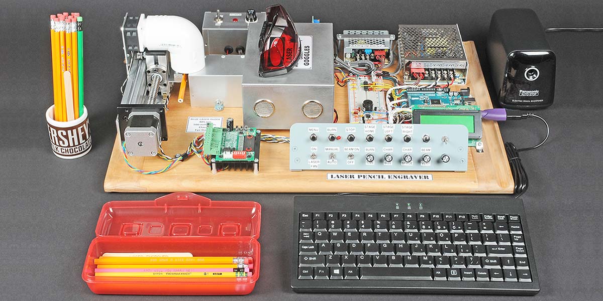
Figure 2 shows the layout of the completed laser engraving system with a keyboard to enter the characters. Just for fun, I decided to build the project in breadboard form, instead of packing it in a big aluminum enclosure. Coincidentally, my wife had recently replaced her old cutting board in the kitchen with a new one.
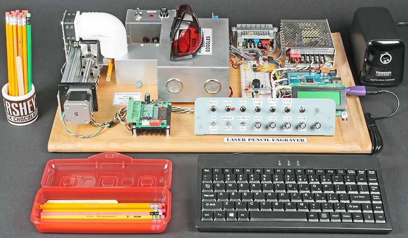
FIGURE 2: The complete laser pencil engraver system built on my wife’s old breadboard.
So, I grabbed the “retired” one and the rest is history. A breadboard on a breadboard. (Pretty silly I know, but I thought it was clever at the time.)
Figure 3 is a more detailed view of the board, with labels on the major parts. Be sure to check it out, so you’ll know which components I’ll be referring to.
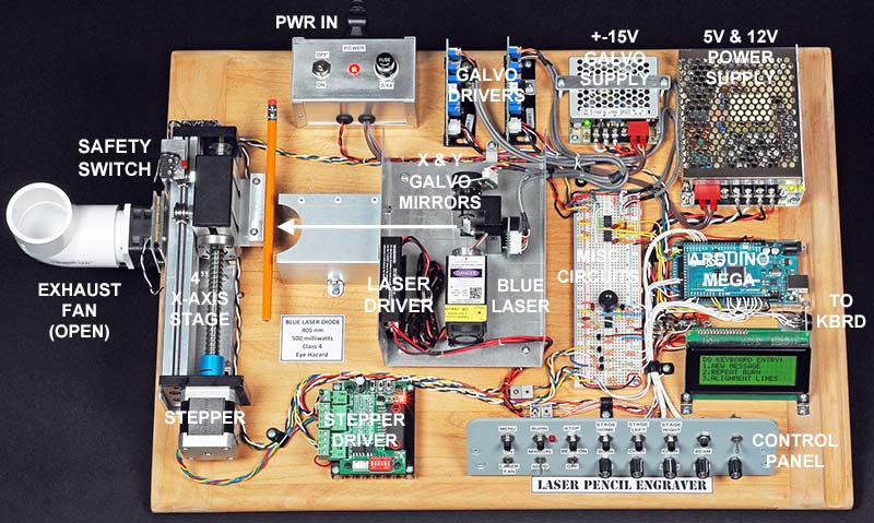
FIGURE 3: The laser engraver with all its components labeled. Note the exhaust fan on the left.
THE MAIN COMPONENTS
The two main components are the 1/2 watt blue laser and two galvanometers (galvos) that steer the beam, as seen in the close-up shot in Figure 4.
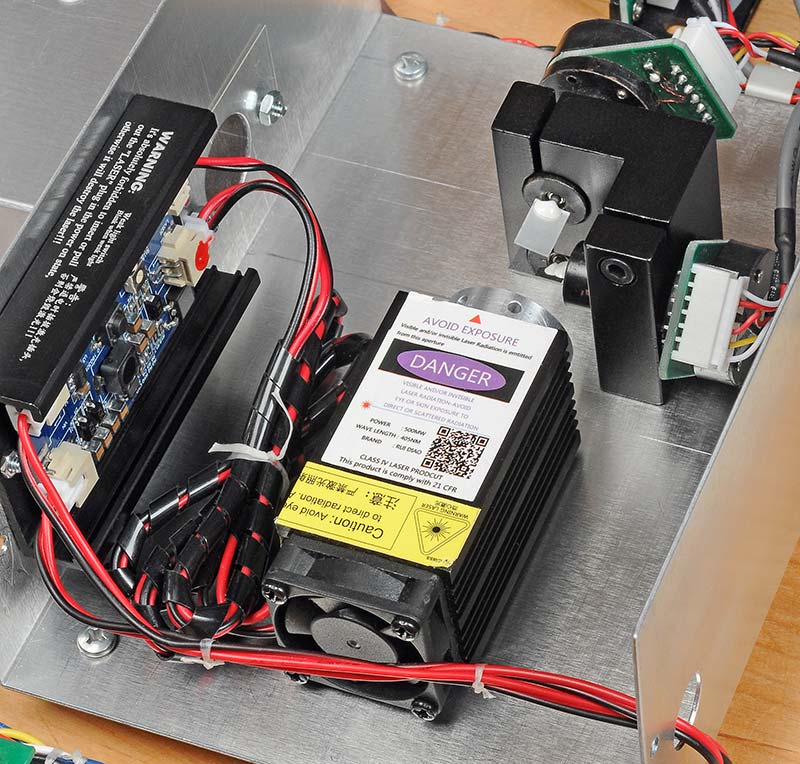
FIGURE 4: The 1/2 watt blue laser bounces off the X and Y galvo steering mirrors and travels six inches to the pencil.
Figure 5 graphically illustrates the laser path and Figure 6 shows how a 5x7 character is formed.
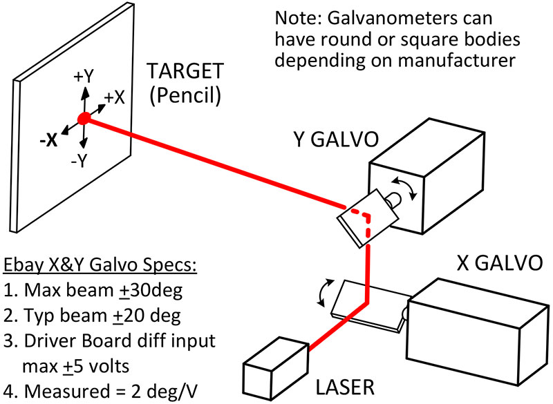
FIGURE 5: You can use a low power red laser pointer to test the galvos before mounting them.
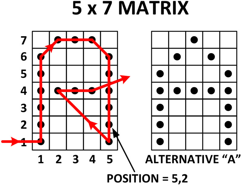
FIGURE 6: The characters are formed using a 5x7 matrix. Adding custom characters is a cinch.
The laser briefly pauses at each dot for about 100 ms and burns a tiny spot. The mirrors then quickly move the beam to the XY coordinates of the next dot, etc.
Both the main components were available on eBay when I wrote this article, so hopefully they’ll still be there when you read this.
The links to them are in the file marked “Downloads 1” with the rest of the article extras. If they aren’t available, there are numerous other similar units that will work. The desired specs are listed in Downloads 1 as well.
The galvo system came complete with the two galvanometers, two driver boards, a ±15V power supply, and all the connecting cables.
In my opinion, the best way to start this project is to buy the laser and galvos, and fire them up on the bench before doing any permanent mounting.
For safety, you can substitute a red laser pointer in place of the more powerful (and not eye-safe) burning laser to test the galvos.
Note that all the tapped holes and mounting hardware of the laser, galvos, and X axis stage are metric. Be sure to use the correct metric screws to mount them.
HOW I CHECKED OUT THE LASER
The laser finally arrived from China after four weeks. I hooked up +12 volts to the Vcc of the power connector and +5V to the TTL/PWM input of the laser driver board (mounted vertically on the left side of Figure 4) in the manner described next; +5V = laser on, 0V = off.
CAUTION: I would suggest connecting an on/off button to the TTL/PWM connector wire coming from the laser driver board. This would allow you to pulse the laser on and off. Terminal #1 of the button should be connected to an external +5V source and terminal #2 to a 1K resistor to ground. Also hook Terminal #2 to the TTL/PWM wire on the driver board. DO NOT let the TTL/PWM wire float because the laser may suddenly turn on. A SPDT button would be suitable too, with no resistor required.
I used a block of wood at a distance of 8” as a target. With the button in my hand, I put on the goggles and pushed it. NOTHING HAPPENED! What the heck!? On, off, on, off, nothing! What’s that smell??? Something was definitely burning, but it wasn’t the wood. I then saw the problem.
I had inadvertently left a small piece of blue painter’s tape on the front of the laser, which I had purposely placed there to keep dust off the lens until I was ready to use it. The tape had a tiny burn spot right in the center.
Believe it or not, I have built and operated lasers for over 40 years and thought I knew what I was doing. After all, it’s not rocket surgery!
Next, I tried some pencils at 8” away, and the smoke came forth. A half second burned a nice spot; two seconds was too much. Success!
The laser had a focusing ring on the front, so I screwed it in and out until the burnt spot on the wood was the smallest.
The little focusing ring was hard to grab, so I added a larger ring that was easier to turn, as seen in Figure 4. I suggest not using plastic materials as targets because the smoke may not be healthy.
HOW TO BE SAFE WITH LASERS
Notice back in Figures 2 and 3 that the optical path to the pencil is completely covered, so there is no chance the beam will “get loose” and hit someone’s eye.
The laser emits a 1/2 watt of blue light which will instantly burn a spot on your retina if you view the direct beam. Reflections from shiny surfaces can also be a problem if they are mirror-like.
I have a pair of goggles that I use, but just to be safe, I always use a 3x5 card or piece of wood as a target to indirectly view the beam.
One time when I was working on a high-energy chemical laser, the beam “got loose” after a mirror fractured from the intense heat.
The uncontrolled beam almost burned its way through an exterior wall made of plaster board and corrugated metal before we hit the red button. Whew!
GALVO CHECKOUT
Figure 5 shows how the galvos are positioned so they steer the beam in the X and Y axes. The shaft/mirror of the galvo is designed to rotate mechanically about ±15 degrees, which translates to an optical beam motion of ±30 degrees. A torsion spring inside returns the shaft to center. There were a gaggle of cables that came with the galvos but absolutely NO instructions on how to hook them up. Luckily, the driver board connectors were keyed.
The three-pin signal input connector had a tiny little + and – marked on the board and the power connector had ±15V. Get out your magnifying glass!
First off, the galvos MUST be powered up to make the mirrors move to their “center” positions. For initial testing, the signal inputs should be shorted or have zero volts on them. Refer to Figure 7 for the schematic. The DACs (digital-to-analog converters) are not needed for these tests.
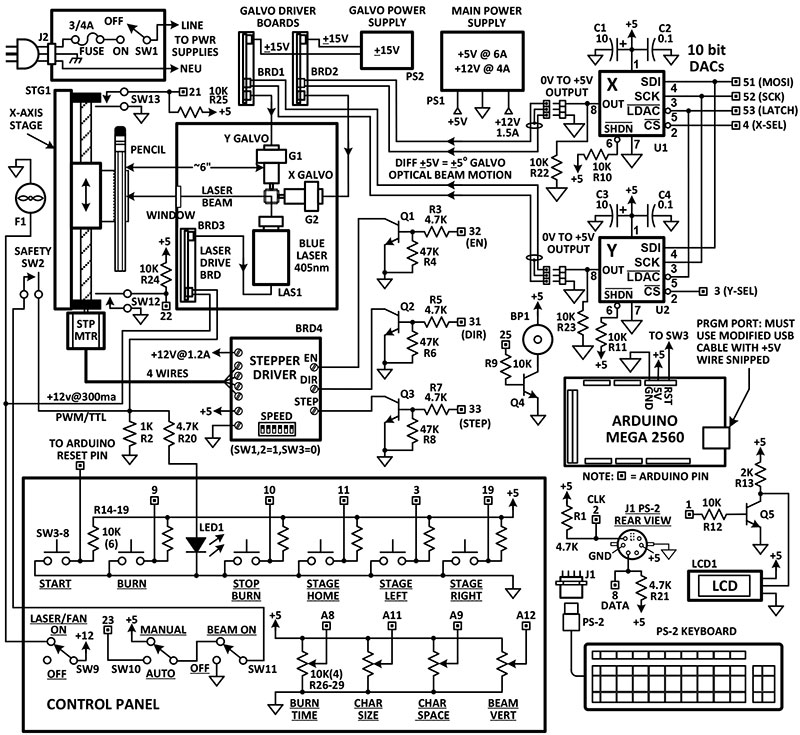
FIGURE 7: The schematic includes serial DACs to drive the galvos. An Arduino Mega 2560 is the master controller.
I set up a red laser pointer so it was 1” from the lower galvo mirror; a piece of white cardboard was 6” away from the upper galvo mirror. I then applied a small voltage (+1.0 VDC) to each of the galvo inputs and noted which way the beam moved. You want it to go in the +X and +Y directions.
Simply reverse (rotate) the three-pin connectors on the ends of the input signal cables to reverse the direction of movement.
In this project, the serial DACs put out 0 to +5 volts, so the galvos only move in one quadrant to form the letters; to the right and up.
I measured the motion of the red laser spot on the screen and it was about 2° (optical) for a 1.0 volt input. That equates to only needing 0.6 volts from the DACs to write a 0.15” high character on a pencil 6” away. Good.
BTW, unless you are a servo guru, DO NOT try to adjust any of the pots on the galvo driver boards because you could destabilize the galvo PID loops. Notice that the pots are locked with a dab of glue and are only meant to be factory adjusted.
DESIGNING THE OPTICAL PATH
I decided not to present any detailed mechanical drawings of the optical components on the breadboard because there are just too many ways to mount them. The only dimensions I suggest you keep in mind are: 1” between the laser and the center of the lower galvo mirror; and 6” from the upper galvo mirror to the pencil.
Try to keep the optical path generally parallel with the plane of the breadboard by mounting the components at right angles to each other and their bases parallel to the breadboard. I chose to put the laser and mirrors inside an aluminum box for eye protection/safety reasons.
A piece of thin plastic forms a window to keep dust off the optics. Any clear plastic will work, although check that it doesn’t absorb too much energy and melt.
MOUNTING THE PENCIL
Here’s a place where innovation could be applied. The real problem is that most No.2 pencils have six sides, and when they are in the right rotation for burning, the bottom of the pencil is resting on a peak, not a flat. I chose the easy way out: double-sided tape!
I made a simple aluminum angle shelf for the pencil and put a thin strip of double-sided tape on the BACK WALL of the shelf. Refer to Figure 8.
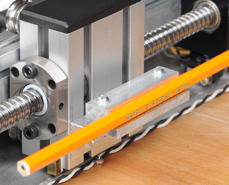
FIGURE 8: The six-sided pencil is held in place on the shelf by a small piece of double-sided tape. Don’t laugh, it works!
To mount a new pencil, I hold it down against the shelf while pressing it against the sticky tape in the rear. (Hey, it works!) I can burn at least a couple dozen pencils before changing the tape.
Of course, there are tons of other ways to mount the pencil, like using a small three-jawed chuck.
My friend, Wayne suggested including an indexed rotation capability, so the pencil could be rotated exactly 60 degrees. This way, all six faces could have a different message.
CRITICAL: ALIGNING THE PENCIL SHELF
This is important! The pencil shelf must be absolutely parallel to the movement of the stage, or the burned characters will “walk off” the pencil. The way I did this was to mount the X axis stage unit on the breadboard such that the centerline of the leadscrew was perfectly parallel with the breadboard base. I then clamped a 12” precision ruler to the pencil shelf.
Finally, I carefully adjusted the rotation of the shelf in the vertical slots of the stage (see Figure 8 again) until each end of the ruler was exactly the same height from the base, ±0.010”. You’re done!
OTHER STUFF
The electronics are pretty standard; refer back to Figure 7. SainSmart sells both the X axis stage and a stepper motor driver board to move it. I chose a 4” stage because 4” of characters fit nicely on a pencil.
Limit switches were added to both ends of the stage because I hate to have it bang into the ends and stall.
Initially, after burning several dozen pencils, I added a small fan and ducting to carry away the smoke because it always seemed to drift directly toward me. (Cough.)
You could add a piece of tubing and route it out a window if the smoke really bothers you or someone else in the area.
Figure 9 shows that the control panel has four pots in the lower right which are used to adjust the characteristics of the characters, like size, spacing, vertical position, and — most importantly — the burn time. Different kinds of pencils require different burn times to get a good image. Too long a time leaves a black mess. Too short and the letters are too light. Be ready to burn up quite a few test pencils at first.
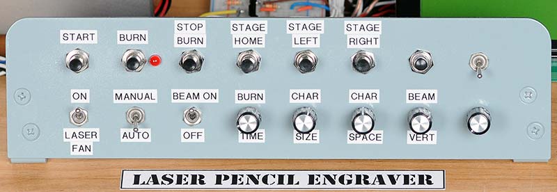
FIGURE 9: The control panel includes four pots to adjust the character burn-time, size, spacing, and vertical location.
The Arduino Mega 2560 microcontroller board was ideal for this application because it had SPI to talk to the DACs, serial for the LCD, a PS2 keyboard header file, and enough interrupts to handle the limit switches and some button inputs. Arduino Unos never seem to have enough pins or interrupts.
The Arduino IDE (integrated development environment) version I used was 1.0.6.1 and it included a keyboard header file that handled PS2 keyboards. It seemed that many full-size USB keyboards — even with USB/PS2 adapters — did not work with it. (Yes, I’ve read numerous articles about adapting keyboards but there is only so much time.)
After trying a bunch of mini and full size AT, PS2, and USB keyboards (plus numerous adapters), I ended up with a mini PS2 with its own adapter. It worked fine and is included in the Parts List.
PARTS LIST
| ITEM |
QTY |
DESCRIPTION |
DIGI-KEY (unless noted) |
| C1,C3 |
2 |
Capacitor, 10 µF, 20V |
478-1840 |
| C2,C4 |
2 |
Capacitor, 0.1 µF, 50V |
478-7340-2-ND |
| R2 |
1 |
Resistor, 1K, 1/4W |
1QBK-ND |
| R13 |
1 |
Resistor, 2K, 1/4W |
2KQBK-ND |
| R1,R3,R5,R7,R20,R21 |
6 |
Resistor, 4.7K, 1/4W |
4.7KQBK-ND |
| R9-R12,R14-R19,R22-R25 |
14 |
Resistor, 10K, 1/4W |
10KQBK-ND |
| R4,R6,R8 |
3 |
Resistor, 47K, 1/4W |
47KQBK-ND |
| R26-R29 |
4 |
Potentiometer, 10K, 1/8” Shaft |
392JB103-ND |
| Q1-Q5 |
5 |
Transistor, NPN, 2N3904 |
2N3904PS |
| U1,U2 |
2 |
DAC, 10-bit, SPI/VREF, 8-pin DIP |
MCP4811-E/P |
| KNOB |
4 |
Knob, for 1/8” Shaft |
679-3543-ND |
| MCU1 |
1 |
Microcontroller, Arduino Mega 2560 |
1050-1018-ND |
| KB1 |
1 |
Keyboard, Mini, PS-2 (see Note below) |
Amazon Adesso EasyTouch110B |
| J1 |
1 |
Receptacle, PS-2, 6-pin |
CP-2860-ND |
| J2 |
1 |
Receptacle, Power, 3-pin, 115 VAC |
Jameco 147901 |
| USB CABLE |
1 |
USB Programming Cable, Modified |
See text and figure |
| LED1 |
1 |
LED, Red |
516-1335-ND |
| F1 |
1 |
Fan, 40x40x20 mm square, 12 VDC |
Jameco 2233166 |
| STG1 |
1 |
Stage, 4 inch travel, w/Stepper Motor |
SainSmart 101-80-124 |
| BRD4 |
1 |
Stepper Motor Driver Board |
SainSmart 101-60-194 |
| PS1 |
1 |
Power Supply, 5V@6A, 12V@4A |
102-2525-ND |
| LCD1 |
1 |
LCD Display, 4x20,Serial In |
Seetron BPP-420L or 420VY |
| FUSE |
1 |
Fuse, 3/4A, 3AG |
F2507-ND |
| FH1 |
1 |
Fuse Holder |
283-2711-ND |
| SW1 |
1 |
Switch, Toggle, SPST, Power |
Jameco 76241 |
| SW2,SW12,SW13 |
3 |
Switch, Micro, Safety and Limit |
Jameco 188867 |
| SW3-SW8 |
6 |
Switch, Mini Button, SPST |
Jameco 26623 |
| SW9-SW11 |
3 |
Switch, Mini Toggle, SPDT |
Jameco 2258486 |
| BP1 |
1 |
Beeper, 5V |
Jameco 138713 |
| LAS1, BRD3 |
1 |
Laser, Blue, 405 nm with Driver Board |
eBay |
| GALVO SYS |
1 |
XY Galvo System, includes: |
eBay |
| G1,G2 |
2 |
Galvanometer with mirror |
|
| BRD1,BRD2 |
2 |
Driver Board, Galvo |
|
| PS2 |
1 |
Power Supply, ±15V |
|
| GOGG |
1 |
Goggles, Laser, 405 nm |
|
| BREADBOARD |
1 |
Wooden Breadboard, 22”x15” used |
My wife’s kitchen |
| WINDOWN |
1 |
Plastic Sheet, thin, 1” sq |
Found item |
| PENCIL |
100 |
Pencil, No.2, Yellow or Light Color |
Staples |
| Note: It appears that some full-size USB keyboards with a USB/PS2 adapter are not compatible. The mini keyboard from Amazon was $19.50 at the time of publication. |
SOFTWARE
Loading, editing, or saving the Arduino sketch for this project required a modified USB cable that had no +5 volts going through it. You still need the data, clock, and ground lines. The problem is that the Arduino Mega is powered by a five volt power supply on the breadboard and a standard USB cable would also try to power it with five volts from the host computer.
This situation causes a conflict which must be eliminated by snipping the +5V wire in the USB programming cable. Please see the file “Downloads 2” in the article downloads for a diagram of how to modify a standard USB cable.
For those of you who are just starting with Arduinos, the ArduinoLaserPencilSketch.ino sketch (file) for this project (also in the article downloads) should be put into a newly created folder named ArduinoLaserPencilSketch. This will enable you to open, edit, and save it back to the folder.
Later on, you may want to edit the sketch and give it a new name before saving it. When you select “Save As” and enter the new name, the Arduino IDE will automatically create a new folder that has exactly the same name as your newly-named sketch. The IDE will automatically place the new sketch inside the new IDE-created folder. Simple!
Bottom line: Every Arduino sketch file (.ino) must be inside a folder with the same name or the Arduino file system will give you an error.
As you can see in the ArduinoLaserPencilSketch file, my software is not pretty but it works. I have annotated it in many places and hopefully you can follow the general flow. Refer to “Downloads 3” for a listing of the Operation Menu on the LCD. The menu starts with:
DO KEYBOARD ENTRY:
- NEW MESSAGE
- REPEAT BURN
- CHARACTER ADJUST
You type in your message; it engraves the pencil; and ends with REMOVE PENCIL.
Not all the ASCII characters are implemented at present, but the usual A-Z, 0-9, and punctuation marks are in the CharacterArray. The lower case letters (a-z) can also be typed in, but that part of the CharacterArray is presently loaded with the coordinates of the upper case letters. Result: The pencil will always get burned with upper case.
If you try to type in a character that is not implemented, the system will not accept it. See “Downloads 4” for instructions on how to add a custom character or fill in the remaining special ASCII characters.
CLOSING COMMENTS
This has been a fun project for me because of my background in lasers. As you can see, there is ample room for changes and innovations, and many custom characters to make.
Lasers can be hazardous but please don’t let that dispel you. By the time you burn your first pencil, it’ll just be another tool. Good luck! I welcome comments and other helpful advice — especially regarding software. NV
Downloads
What’s in the zip?
Code File
Laser Specs
How Tos