Recently, I had the opportunity to work with the Dr. Duino Explorer board and have been quite impressed with it. This is a full-featured prototyping board for Arduino Uno or Nano compatible boards. The Explorer comes as a kit and the parts used need to be soldered onto a printed circuit board (PCB).
The kit comes with very detailed instructions for the assembly which is ideal for a beginner and an easy walkthrough for the more experienced. It's these fine details which make for a successful build.
Assembly details, warnings about incorrect procedures, and soldering and troubleshooting tips are also included..
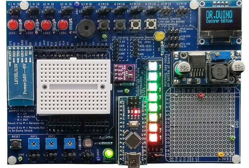
Figure 1. The Dr. Duino Explorer shield.
What really makes this kit shine, however, is the Diagnostic Equipment Course (DEC for short) which turns the Dr. Duino Explorer into a digital multimeter and basic oscilloscope.
This isn’t your ordinary online course though. The DEC is meant to teach the end user how to build the core functions of a DMM; specifically, a voltmeter, ohmmeter, ammeter, and continuity meter.
The course finishes with having the user transform the Dr.Duino Explorer into a very basic oscilloscope. This was perhaps my favorite part.
What makes this course truly unique is the fact that it’s taught in a fundamentally different way than any other electronics course I’ve seen before.
The folks over at Dr. Duino use what they call a “Layered Learning” approach to teaching this course. They start with teaching the fundamentals of how analog-to-digital converters (ADCs) work and slowly layer new concepts on top of one another.
This really provided a great foundation which, by the end, made me feel like I could tackle any analog-to-digital based project.
Instead of just providing some code and a schematic, they went through the nitty gritty details of how it works from the microcontroller's vantage point. They then layered on a review of basic electronic theory and finally the code. It was really a lot of fun to work through.
By the end of the course, you have an excellent understanding as to how analog-to-digital converters work while creating your own DMM and basic oscilloscope.
Here’s how it starts.
Logging Into Dr. Duino’s Labs
Armed with a Explorer, I logged into their course area which is called Dr. Duino’s Labs. This is where the assembly manual and this new DEC add-on can be found. The course is laid out logically and walks you through each and every project one step at a time.
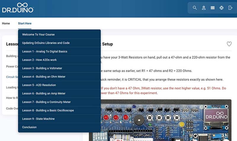
Figure 2. Dr. Duino’s DEC course.
After some initial background and library updates, the course begins and you are quickly sucked into the awesome world of analog-to-digital converters.
Back to Basics: How ADCs Work Simplified!
The DEC begins by teaching electronic signal fundamentals (e.g., analog vs. digital signals). This serves to build a solid foundation for the remainder of the course.
It then teaches you how analog signals are digitized by the Arduino Nano’s onboard ADC; specifically, SAR ADCs are reviewed in depth. (SAR is short for Successive Approximation Registers and is used in thousands of various microcontrollers.)
Part of the online course includes a great video in which they teach you exactly how it works from the hardware’s vantage point but in a very easy-to-follow manner.
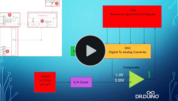
Figure 3. "How SAR’s Work" explainer video.
This video demonstrates how the SAR translates a 0-5V signal into a digital value (0-1023 bits), which you then use to create your DMM or basic oscilloscope.
This is a real deep dive into exactly how it works. They even have a downloadable spreadsheet which allows you to simulate digitizing an analog signal into a digital one. It’s a really fun and nice touch.
Next Up, Building a Voltmeter
One of the things I really enjoyed is the fact that the course didn’t go into miles of formulas to show me how to build the DMM and basic o'scope. Instead, it focused on the core basics of what you actually need in order to perform its analog-to-digital magic.
Using the Dr.Duino’s built-in potentiometers, the user is taught how to digitize the value read from the pot, scale it to the appropriate value, and then ship it over to the onboard OLED.
Building an Ohm, Continuity, and Ammeter
Remember the layered learning approach mentioned earlier? Well, this is where you really start to see the power of this technique. Everything you’ll learn up to this point is now built upon to create the next few projects (ohmmeter, continuity, and ammeter).
If you’re a bit rusty on the basics (like many of us), then this portion of the course will be a breath of fresh air. In order to build all the projects inclued, the user needs to review some basic electronics such as resistor divider networks and power dissipation calculations.
It has you build up a very simple resistor divider network to efficiently measure various voltage values using the Explorer’s built-in breadboard. Depending on which mode you are currently in, the combination of resistors and voltage outputs is then translated into ohms, volts, amps, continuity tester, and even a basic scope.
Much like the build of the Dr. Duino Explorer itself, you can expect highly visual and detailed examples which walk you through the entire course like you see in Figure 4.
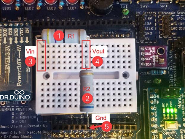
Figure 4. Building a resistor divider network.
It’s All About the Gotchas!
One thing I found rather refreshing was the detail to the little things that you usually have to stumble on, through, and over to figure out. The team at Dr. Duino goes to great lengths to explain things like analog-to-digital resolution issues and why it’s so important to take it into consideration when building a project. It really made me feel like I’m ready to tackle any analog-to-digital based project I can dream up.
Oscilloscope Mode, le pièce de ré·sis·tance!
One of the features that really interested me was using the Explorer as a simple oscilloscope.
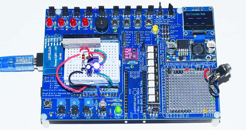
Figure 5. Using the Explorer as a simple oscilloscope.
To do this, I ran the Dr. Duino Oscilloscope program which is included in Dr. Duino's DEC Course Suite. This program uses the OLED display to capture a waveform. The program is set up to read the potentiometer 3 component on the Explorer board which is connected to pin A2 on the Arduino.
Instead of using the potentiometer, I unplugged the JP16 jumper used with pot 3 and then plugged it back into the left and center pins of the header to isolate this pin.
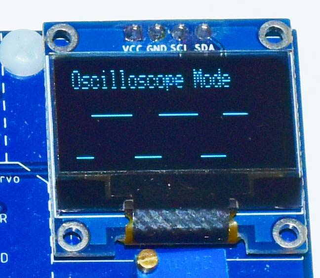
Figure 6. The OLED display used as an oscilloscope, showing the 555 timer waveform.
This isolated pin A2 was then connected to pin 3 of a 555 timer IC that I mounted on the white breadboard. I chose resistor and capacitor values for the 555 timer to output a square wave of just over 1 Hz.
Dr. Duino's Oscilloscope program writes to the OLED in real time; i.e., it reads the A2 pin value and then immediately maps it to the OLED display 128 times (the width in pixels of the display) in a loop that takes about 2.4 seconds.
With a sweep time of 2.4 seconds, you won't be able to see the details of waveforms of a much higher frequency. However ,a couple of simple changes in the RunOscilloscope() function of the program can improve this:
void RunOscilloscope()
{
int my555[128];
display.clearDisplay();
display.setCursor(0, 0);
display.setTextSize(1);
display.println(("Oscilloscope Mode"));
display.display();
for (int i = 0; i < 128; i++)
{
my555[i] = analogRead(A2);
}
for ( int Xaxis =0; Xaxis < 128; Xaxis ++)
{
display.drawPixel(Xaxis, map(my555[Xaxis] , 0, 1023, 31, 9), WHITE);
display.display();
}
delay(1000);
}
Instead of doing the analogRead() and then immediately writing to the OLED display, all 128 analogRead() values are first read and stored in an integer array and then written to the OLED display. This improves the sweep time.
Timing the analogRead() loop showed it takes about 15 milliseconds to do the 128 reads and store them in an array. This will improve the frequency that can be plotted to well over a kilohertz. Delays can be incorporated in the analogRead() loop to adjust the sweep time of the display to accommodate a specific frequency.
While this simple display can't compare with a dedicated oscilloscope, it does have real value. When building a circuit, it's often the case that there's a signal you need to know is working and whose frequency is so high it can't be viewed with a simple flashing LED. You want a simple go or no-go test to tell you if there is a good signal on this line and the Explorer is perfect for this task.
I can certainly recommend Dr. Duino’s Explorer Board. It will be an asset to both beginner and experienced users. If you'd like more information about the Dr.Duino Explorer and the Diagnostic Equipment Course, visit Dr. Duino's website. NV
While both an Arduino Uno and a Nano can't be plugged into the Explorer at the same time, a second Arduino Nano can be plugged into the white breadboard. This will isolate it from the rest of the board. Jumpers to the Arduino Uno headers above and below the white breadboard or those in the 256-pin prototyping area can then be used to communicate between the two Arduino Nanos.
One of my past breadboard experiments comes to mind. Two Arduino Nanos needed to be connected together — communicating through serial ports — using the Arduino Software Serial library. The question was, when using a twisted pair from an Ethernet Cat 5 cable, can I get a good signal through 50 feet of cable? The answer was yes.