Most LED projects involve some wiring, some resistors, a solderless breadboard, and a bunch of jumper wires. Not this one! You can create bright, stunning colors by literally just plugging LEDs directly into the Arduino pins. No wiring, no resistors. Just your Arduino and a handful of LEDs.
The is the absolute simplest and lowest cost way to get started manipulating light and color. I’ll show you how to do it safely in this article.
What You Will Need
All you need for all the projects in this article is an Arduino and some LEDs. If you have them already, you’re set. If you don’t, you can purchase an Arduino for less than $4 from websites such as Aliexpress.com.
If you need some LEDs to get you started, you can purchase a kit of 100 ultrabright LEDs in five different colors. And, if you’re looking for the best “getting started” kit for LEDs that includes resistors, a solderless breadboard, and jumper wires, you can also get one of these for less than $2.
These three starter kits are shown in Figure 1.
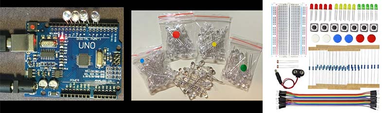
FIGURE 1. You can purchase all three kits for under $8. See the Resources for details.
Check the Resources for my blog posts about each kit and where to purchase them all for less than $8.
Basic LED Properties
LED stands for Light Emitting Diode. The diode part means current only flows in one direction. The lead that is connected to the positive voltage is the anode and the more negative lead is the cathode. Every diode has two ways of telling which lead is which.
Look at an LED closely. The longer lead is the anode and the shorter lead is the cathode. While the plastic dome of the LED looks round, it actually has a flat on the rim. The flat is adjacent to the cathode of the LED. These features are shown in Figure 2.
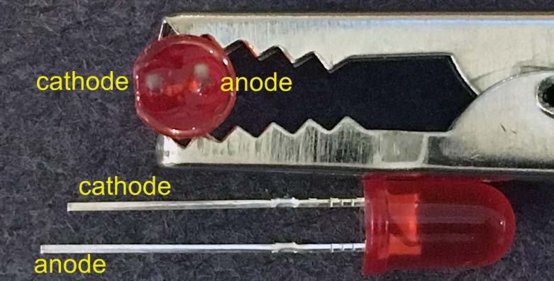
FIGURE 2. Example of the two features to show the cathode and anode leads of the LED.
There are three important properties of every diode:
- When connected in the reverse direction, there is no current through an LED. It looks like an open.
- When connected in the forward direction below an applied voltage (called the forward voltage drop, FVD), the resistance is infinite. As the applied voltage across the LED increases above the FVD, the voltage across the diode is constant at the FVD and its resistance is zero.
- Up to a maximum current, the light it emits is proportional to the current through it. Above the maximum rated current, the LED may be damaged.
Getting the Most Current Out of an Arduino Pin
If you look at most Arduino projects that involve LEDs, they all show you an LED plugged into a solderless breadboard with a resistor in series to limit the current and jumper wires going back to the Arduino digital pins.
There’s a much easier way of driving an LED: Just plug it directly into the Arduino digital pin header. But wait! Doesn’t every project book, online resource, and workshop say never plug an LED directly into a digital pin? Won’t that damage the Arduino or the LED?
The microcontroller on the Arduino Uno board is the ATmega328. In its specs, it says the maximum current draw for the entire chip is 200 mA and the maximum rated output current per pin is 40 mA. This doesn’t mean you can only get 40 mA out of the pin.
It means that if you do draw more than 40 mA, the reliability of the ATmega328 might be compromised. Maybe the noise will be higher, the power dissipation will be higher, or maybe the power rail voltage will be reduced. Any of these problems might cause bit failures.
It’s all about how much risk we’re willing to take. In all my experiences drawing more than 250 mA from the digital pins for days at a time, I have never had an Arduino or LED failure. Just remember the hacker’s code: If you don’t break something every now and then, you are not pushing the limits far enough.
Each digital I/O on the Arduino actually has some output resistance built into it from its output transistor built on the die. This resistance is a little non-linear. At low current draw (like 20 mA), it’s about 28 ohms. At high current draw, it goes up to as much as 60 ohms. When we plug an LED directly into the digital I/O, it’s this internal output resistance that limits the current.
It’s easy to measure this current using a simple DMM (Digital MultiMeter) as an ammeter.
I set digital pin 13 to a HIGH and shorted the output through an ammeter to ground. The ammeter had a series resistance of only one ohm; small compared to the Arduino’s output resistance. The short circuit current I measured was 83 mA.
There’s only one ground (gnd) pin near the digital pins. However, we can use a digital pin set as a LOW to act as a sink for current. When I shorted a HIGH pin to a LOW pin with the ammeter, I measured 70 mA.
These represent the absolute maximum current we can get out of a digital pin, in the best case. When we short the pins with an LED, the FVD of the LED reduces the current draw. There are generally two types of LEDs with two different FVD.
LEDs made with a Gallium-Arsenide-Phosphide material with a low brightness have an FVD of about 2V. These usually have a colored dome and come in red, yellow, orange, and green. LEDs made with an Indium-Gallium-Nitride process — which are usually ultra-brights — have an FVD of about 2.9V.
These usually have untinted clear domes and come in green, blue, and white.
The maximum current we get with each LED connected across a HIGH pin and ground or a HIGH pin and a LOW pin for each of the families of LEDs is summarized in Table 1.
| |
HIGH pin to gnd |
HIGH pin to LOW pin |
| Shorted directly through the ammeter |
83 mA |
70 mA |
| Shorted through the red LED |
75 mA |
52 mA |
| Shorted through the blue LED |
50 mA |
33 mA |
TABLE 1.
These currents exceed the maximum rated current of a digital pin and exceed the 20 mA maximum rated current of most LEDs.
You will not damage your Arduino and you will not damage your LED.
I reserve pin 13 to drive an LED to the adjacent ground, and pins 12, 10, 8, 6, and 4 to connect the LED to the adjacent pins which are set as a LOW. The anode (long lead) goes into the HIGH pin and the cathode (short lead) goes into the ground or LOW pin.
Adding a Heartbeat to Your Arduino
The first step in direct driving an LED is to add a heartbeat to your Arduino. If you can write the Blink sketch, you can modify it to change the pattern from blink...blink...blink...blink to a heartbeat: thump-thump...thump-thump...thump-thump.
Here’s my simple code to drive pin 13 like a heartbeat:
//it’s alive
void setup() {
pinMode(13, OUTPUT);
}
void loop() {
digitalWrite(13, HIGH);
delay(100);
digitalWrite(13, LOW);
delay(100);
digitalWrite(13, HIGH);
delay(100);
digitalWrite(13, LOW);
delay(500);
}
When you can flash the onboard LED, pin 13, with the pattern you want, just insert a red LED (has to be red if it’s a heartbeat) between pin 13 and the adjacent ground pin and you have an instant, very bright heartbeat that can light up a dark room with the pulsing beat of a throbbing heart.
This trick works with any Arduino — even the SparkFun RedBoard — shown in Figure 3.
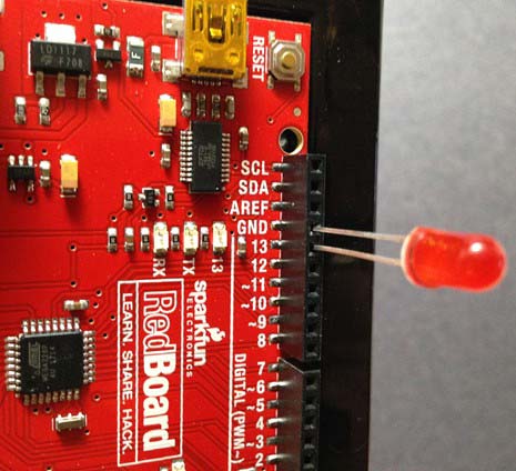
FIGURE 3. Insert a red LED between pin 13 and ground to give your Arduino a heartbeat.
When the LED flashes, there will be 75 mA through the LED. If you use a superbright LED, it will be the brightest LED you ever saw. Don’t look directly into it or it will leave a bright afterimage for minutes.
Any pattern with which you can drive the onboard LED can also direct drive any LED inserted into pin 13.
An ultrabright LED has the clear untinted plastic dome. There’s no way of telling what color it is unless it’s on. The simplest way of testing a clear LED is by running Blink or this code and inserting the LED between pin 13 and ground. You’ll know instantly what color it is.
Driving Five LEDs Simultaneously: A Flashlight
We can direct drive up to five LEDs using the trick of plugging them between a HIGH and a LOW pin. If it’s a red LED, we’ll get about 52 mA per LED. This is a total of 260 mA current draw from the ATmega328. This exceeds the maximum current rating of the chip.
The power consumption in the ATmega328 chip is about 5V x 0.26A = 1.3 watts. The chip will get noticeably warm but there is no danger of smoking. I’m willing to take the risk of exceeding the maximum ratings. Just be sure you are before you try this. Figure 4 shows my Arduino with five direct drive LEDs.
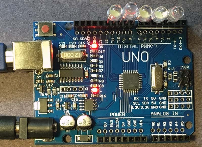
FIGURE 4. An example of an Arduino with five direct drive LEDs.
If it’s a blue LED, we’ll get about 33 mA per LED, or a total of 165 mA from all five. If we drive all of them the same, we can make a pretty bright flashlight, a flasher, or a strobe.
The general code to drive a pulse train on all the even pins is very simple. Using the delay() function, we can control timing to within 1 msec. This is okay for most applications. I wrote a simple sketch that synthesizes a pulse train with a period and duty cycle with all the pins the same.
If the period is less than 24 msec, the LEDs flash faster than the persistence of vision and they appear to be on continuously. By adjusting the duty cycle, we can change the relative brightness. A value of one means it’s on all the time. A value of 0.05 means it’s on for just 5% of the time and is dimmer.
We can also design a strobe signal with an on time of 1 msec and an off time of 500 msec, for example.
Here’s my generic sketch:
int iPeriod_msec = 21;
float dutyCycle = 0.5;
int iTimeOn_msec = iPeriod_msec * dutyCycle;
int iTimeOff_msec = iPeriod_msec * (1 - dutyCycle);
void setup() {
pinMode(12, OUTPUT);
pinMode(11, OUTPUT);
pinMode(10, OUTPUT);
pinMode(9, OUTPUT);
pinMode(8, OUTPUT);
pinMode(7, OUTPUT);
pinMode(6, OUTPUT);
pinMode(5, OUTPUT);
pinMode(4, OUTPUT);
pinMode(3, OUTPUT);
digitalWrite(11, LOW);
digitalWrite(9, LOW);
digitalWrite(7, LOW);
digitalWrite(5, LOW);
digitalWrite(3, LOW);
}
void loop() {
digitalWrite(12, HIGH);
digitalWrite(10, HIGH);
digitalWrite(8, HIGH);
digitalWrite(6, HIGH);
digitalWrite(4, HIGH);
delay(iTimeOn_msec);
digitalWrite(12, LOW);
digitalWrite(10, LOW);
digitalWrite(8, LOW);
digitalWrite(6, LOW);
digitalWrite(4, LOW);
delay(iTimeOff_msec);
}
Direct Drive a Three-Color LED
To drive five LEDs using this trick of an adjacent pin set as LOW, we wrote our own code to pulse width modulate (PWM) the five HIGH pins directly. This required all five LEDs to be driven with the same signal.
We can do this same thing using the built-in PWM feature available on some pins. The perfect application for this is when direct driving a three-color LED. These are single LED packages which actually have a red, green, and blue LED inside.
The PWM feature is controlled by the analogWrite function. This allows eight-bit resolution or 256 levels of duty cycle. The modulation frequency is 490 Hz, and the level controls the duty cycle. With three different colors which can have 256 levels of brightness, we can make 28 x 28 x 28 = 24-bit levels of color.
This is more than 16 million different colors by modulating the relative brightness of the red, green, and blue lights.
Normally, three LEDs would require six leads. However, the cathodes of each of them are connected in common. This means only four pins are required. The cathode connects to the LOW pin and the three anode leads are available to connect to the PWM pins of the Arduino. Some three-color LEDs have a common anode with the individual cathode leads available. Be sure to note which one you have.
You can purchase 10 of these three-color LEDs for under $1, shipping included. Check the Resources for purchasing information. Figure 5 shows an example of one of these three-color LEDs with the pins identified.
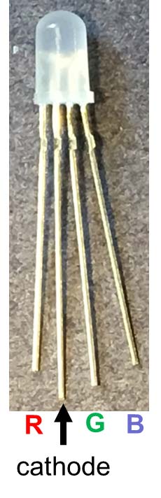
FIGURE 5. Example of a three-color LED with the leads identified. This is a common cathode LED. Note: Not all three-color LEDs have this pin configuration. You may have to experiment with your three-color LED.
The PWM pins in an Arduino Uno are identified with a little ~ mark next to the digital pin number. We want to use three PWM pins next to each other and an adjacent pin as the LOW.
A good choice is to use:
- Pin 12 as LOW
- Pin 11 as R
- Pin 10 as G
- Pin 9 as B
All we need to do is bend the leads slightly to fit into these header pins. A three-color LED mounted in the Arduino header pins is shown in Figure 6.
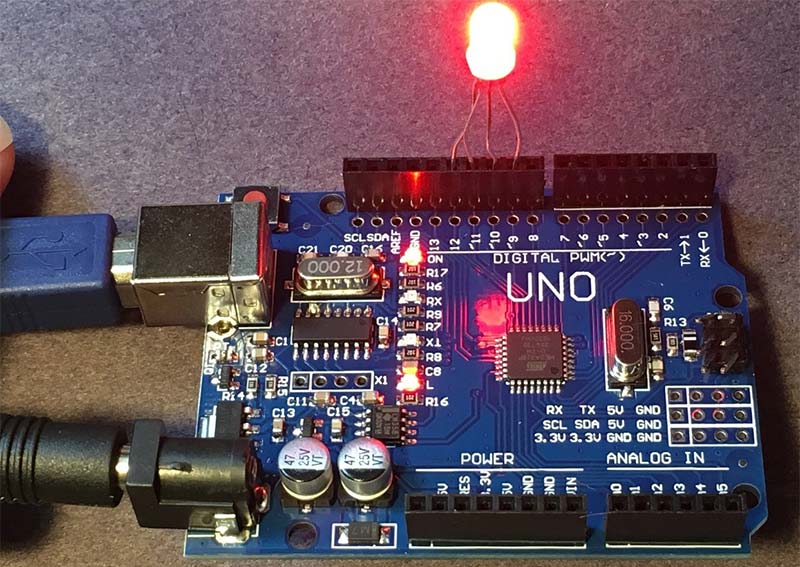
FIGURE 6. A three-color LED inserted in an Arduino with the red pin at level 255.
To drive these colors, we just need to set up the pins and use the analogWrite command to select the color intensity of the red, green, and blue lights. Here’s a simple sketch to alternate through each color one at a time:
int pinR = 11;
int pinG = 10;
int pinB = 9;
int pinCathode = 12;
void setup() {
pinMode(pinG, OUTPUT); //green
pinMode(pinB, OUTPUT); //blue
pinMode(pinR, OUTPUT); //red
pinMode(pinCathode, OUTPUT);
digitalWrite(pinCathode, LOW);
}
void loop() {
analogWrite(pinR, 255);
delay(1000);
analogWrite(pinR, 0);
analogWrite(pinG, 255);
delay(1000);
analogWrite(pinG, 0);
analogWrite(pinB, 255);
delay(1000);
analogWrite(pinB, 0);
delay(2000);
}
Random Colors
There are lots of quick simple ways of manipulating the lights. I like putting on a little light show by making the colors change randomly.
I introduce the new variable as the on time and select each color level as a random number using the random(0, 256) function. This function selects a random integer between the two limits of 0, inclusive to below 256.
The sketch to do this is just slightly modified from the previous sketch. Running this sketch makes the LED flash a different color every 0.5 seconds, selected at random:
int iTimeOn_msec=500;
int pinR = 11;
int pinG = 10;
int pinB = 9;
int pinCathode = 12;
void setup() {
pinMode(pinG, OUTPUT); //green
pinMode(pinB, OUTPUT); //blue
pinMode(pinR, OUTPUT); //red
pinMode(pinCathode, OUTPUT);
digitalWrite(pinCathode, LOW);
}
void loop() {
analogWrite(pinR, random(0,256));
analogWrite(pinG, random(0,256));
analogWrite(pinB, random(0,256));
delay(iTimeOn_msec);
}
It’s remarkable how it’s possible to make so many distinctly different colors with just three primary colors.
Summary
Want to get started with bright lights and Arduinos, with no fuss, no wiring, no resistors — just plug and play? It doesn’t get any simpler or any cheaper than direct driving LEDs using a low-cost Arduino and low-cost LED kits.
The methods illustrated in this article will get you started with instant LED projects. NV
Resources