For a bold and eye-catching output display in your next electronic masterpiece, consider exploiting a matrix LED device. As the name implies, this is an array of single LEDs arranged in rows and columns. When a particular intersection is specified, the LED element there turns on and shines away. Then, for example, groups of these can be selected to build up a pattern within a complete column. Finally, by rapidly sequencing a series of columns one after another (a process called multiplexing), a complete character is formed. Persistence of vision gives the illusion that all of the LEDs which make up the character are lit simultaneously. All in all, it's a pretty slick system and virtually open-ended. You'll be able to create just about any symbol or pattern you want, and can even animate things for some action-packed results.
Of course, you could always build your own matrix from discrete LEDs, but it’s dispiriting to think of all the soldering that would entail. Fortunately, prefabricated packages arranged in rows and columns are available which completely eliminate that drudgery. Even better is that now these show up in surplus electronics stores, often for a pittance. The time has never been better to learn all about matrix LEDs, so let’s dig in! Since we’ll be utilizing a PIC, it is assumed the reader already has a basic understanding of how microcontrollers work.
What’s Inside?
I used the LJ7071-22 five-by-seven LED matrix manufactured by Ledtech Electronics Corporation, it should be representative of most monochrome (one color) devices. You can download the datasheet for this part from www.allelectronics.com. Since the display is organized as five columns by seven rows, it’s no great surprise that this comes in a 12-pin package. The form factor is the usual DIP size, and you can plug it into a 14-pin socket if desired, leaving two spots empty. Let’s look more closely at how things are organized within the part.
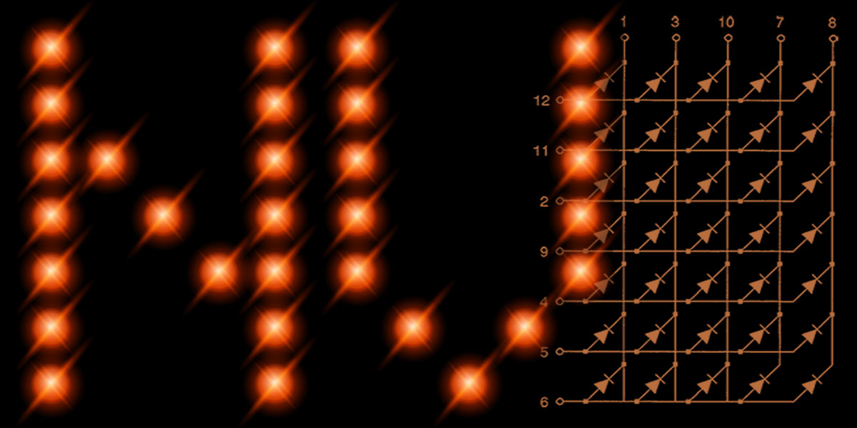
Refer to Figure 1 which shows the arrangement.
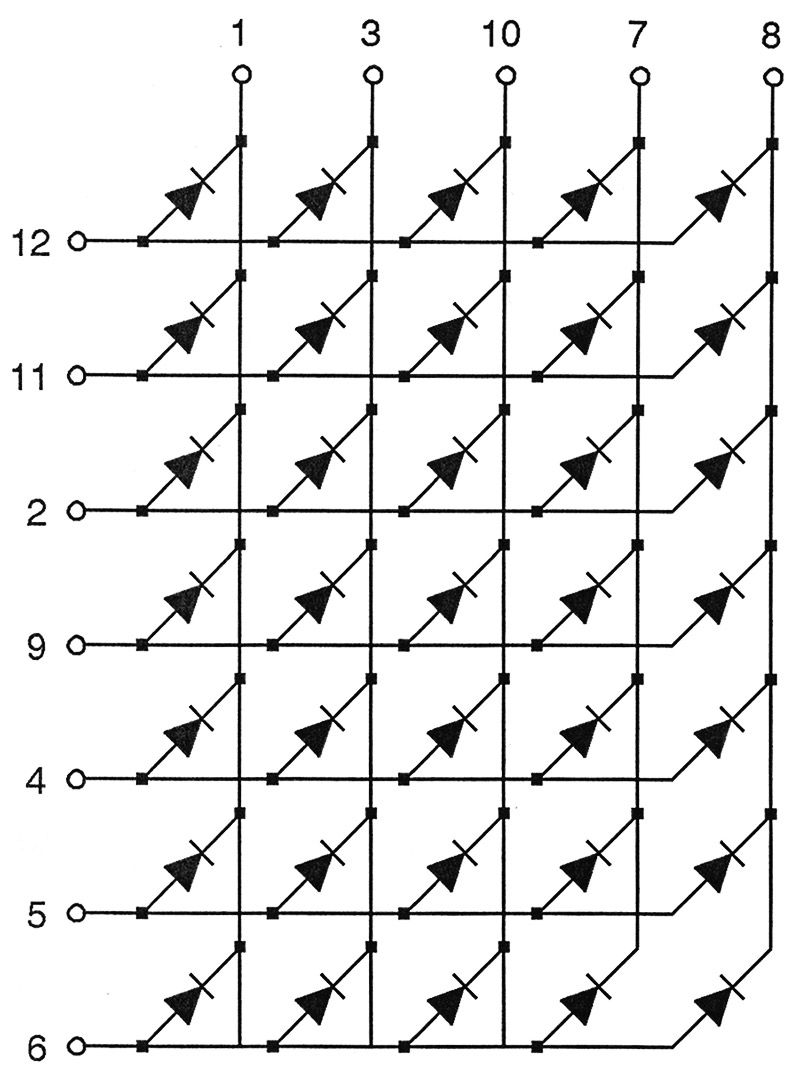
FIGURE 1. This is the LED arrangement and pinout of the Ledtech Electronics Corporation LJ7071-22 LED matrix display. Check your datasheet if using an alternative.
In this schematic view, a dot indicates an electrical connection. Otherwise, crossing lines are of no significance. Right away, we see that each of the five columns is a common cathode connection, while each of the seven rows gang common anodes. By grounding a column line and applying a positive voltage to a row line, the LED at that intersection lights up. Don’t do that quite yet, however, because we still need to add in a bit of support circuitry; if nothing else, some current-limiting resistors.
For reference, I’ve shown the pin numbers for the device I’m using. In general, it’s probably more logical in what follows to call out the rows and columns. Just refer back to Figure 1 when wiring things up. Of course, if you’re using another unit, then the pinout could be different and you’ll need to refer to the appropriate datasheet.
The Basic Configuration
To turn this into a fully functional character display requires just a handful of common external components. Figure 2 shows a practical arrangement.
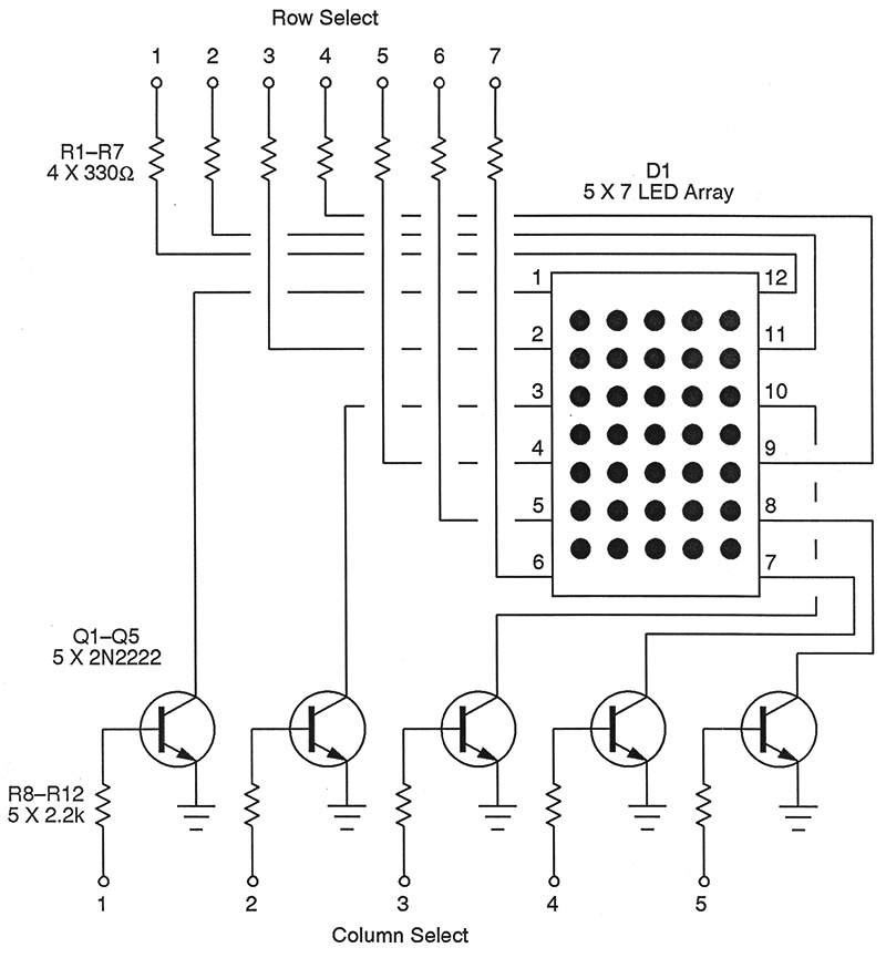
FIGURE 2. Drive this single-character display directly with the PIC circuit of Figure 3. Port A controls the columns, while port B controls the rows.
Each of the rows is fed by a current-limiting resistor, and there are seven of these. The five columns, on the other hand, are controlled by transistors. Here, we use the ever-popular 2N2222. Think of these as voltage controlled switches. When a transistor is turned on, the common cathodes of the selected column are connected to ground and the chosen LEDs light up. We need a transistor, naturally, because more than one LED in a column could be lit. In other words, we might need to sink as much as 70 mA (assuming 10 mA per LED), and the 2N2222 can easily handle that. Note, however, we must make certain that only one column is selected at a time. More about that in a moment.
To aid your understanding, you can breadboard this affair as-is and test it by applying +5V to various row and column select inputs. For example, by applying +5V to resistors R1 and R8, the LED dot in the upper left-hand corner will light. By the way, did you notice that this arrangement responds to positive logic? The transistors have the happy side-effect of inverting the sense of things. That sure makes life simpler when trying to sort out bit codes for user-defined characters.
While it’s instructive to see how this works with jumper wires choosing a row and column, it’s pretty obvious we’ll want to turn more extensive duties over to a microcontroller. The currents required by the matrix LED arrangement in Figure 2 are well within the capabilities of most modern microcontrollers. Plan on 10 mA per row and less than 1 mA per column. Just make sure that only one column is chosen at a time. Otherwise, a row select line would be asked to supply more than the requisite 10 mA, putting the microcontroller at risk.
Connect It to a Microcontroller
I like designing with PIC microcontrollers, but the logic of what we’ll be doing is much the same for AVRs, Arduinos, and the like. Figure 3 shows how the ubiquitous PIC16F88 can be pressed into service.
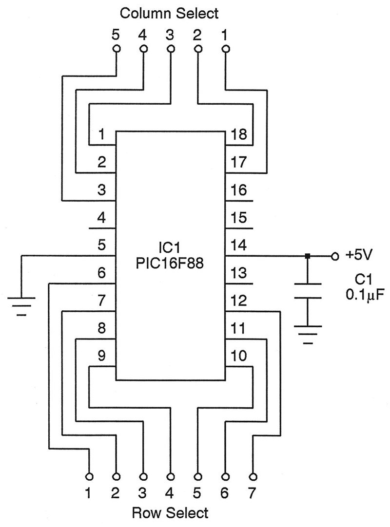
FIGURE 3. The PIC is labeled like this when the matrix LED is used vertically. Swap rows and columns when connected horizontally.
With a couple restrictions, there are essentially two eight-bit ports at our disposal. Five lines of port A are used to control the columns, while seven lines of port B handle the rows. This still leaves a few port pins left over for other uses. Just in case it isn’t clear, we’ll run things on the built-in 8 MHz clock, and also let power-on resets be handled internally.
So, just connect things up as in Figures 2 and 3, and away you go! Figure 4 shows what the breadboarded result looks like.
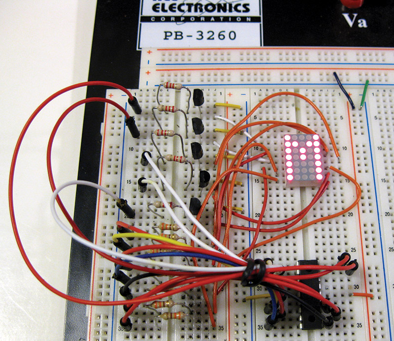
FIGURE 4.
We still have to figure out the software. Get the download package at the end of this article. In there, you will find the complete source code which drives our single character display. In particular, the firmware will put the unit through its paces, showing all of the standard ASCII characters including upper- and lower-case letters, digits, and punctuation. See the sidebar below for more information on the programs.
About the Firmware
The complete source code for the firmware (available at the article link) has been written in the free and open source Great Cow Basic language, which itself is available from gcbasic.sourceforge.net. This really is an easy-to-use yet powerful package, and it’s completely free — no strings attached! The three main source files and their purposes are:
OneChar.GCB — Display a single ASCII character
TwoChar.GCB — Display two ASCII characters
Horizontal.GCB — Display two digits horizontally on a single matrix LED
You'll also find two "include" files:
Characters.GCB — Bit codes for ASCII characters 32 through 127
Digits.GCB — Bit codes for 3 x 5 digits using negative logic
Bear in mind that Great Cow Basic files are really just ordinary text, so even if you're using an Arduino, for example, you'll be able to rip off the character bit codes and exploit them. That'll save you tons of time because designing a complete character set is usually fairly time-consuming.
Finally, the source code is heavily annotated. Thus, you'll be able to learn how the data is stored in tables and accessed; how Timer 0 is used to multiplex the columns; and so on. In short, perusing the code is a great educational endeavor. Of course, the comments also simplify the task of porting the code to other languages or processors should that be part of your agenda.
More Than One Character
Once you’ve figured out how to display a single character, it’s pretty straightforward to extend this to longer messages. After all, each new character represents little more than five additional columns to be scanned. Theoretically, this ought to be easy, but after a moment’s reflection it’ll dawn on you that you may run out of port lines on the microcontroller. Here’s one approach that keeps things manageable when displaying two-digit numbers.
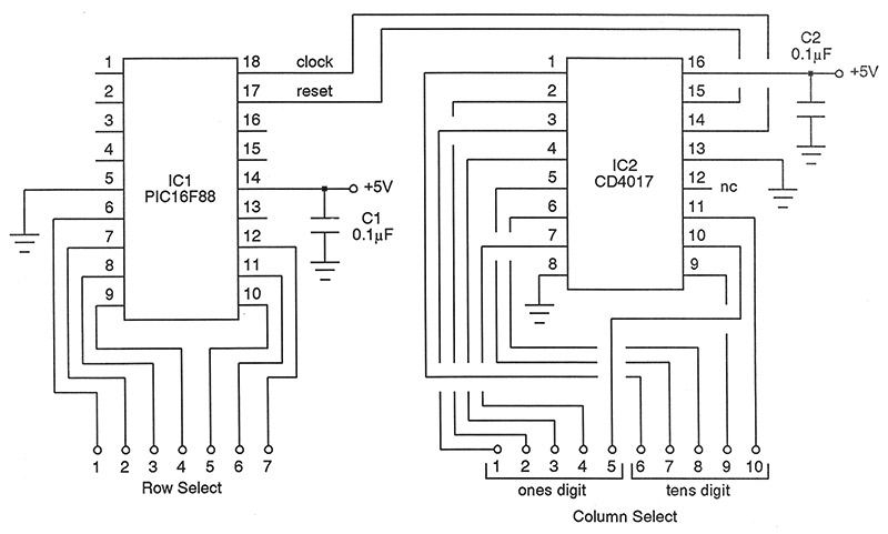
FIGURE 5. For this two-digit display, duplicate Q1-Q5 and R8-R12 in Figure 2, and parallel row pins 12, 11, 2, 9, 4, 5, and 6, respectively, of the two display devices.
Figure 5 gives us the scoop. A CD4017 divide-by-ten counter is called upon to service the column select lines. Hey, that’s pretty nice: Two characters of five columns each require 10 control lines — exactly what this CMOS chip has. Now, it’s just a matter of stepping the counter along to multiplex the columns sequentially. All that’s needed is a microcontroller port pin to clock the device, and a reset line to ensure the counting commences from the beginning.
So, to make a two-character display, repeat the circuitry of Figure 2 for a total of 10 columns (10 transistors and 10 base resistors). Then, gang the row pins of the two matrix LEDs. For example, row resistor R1 goes to pin 12 of both display devices; R2 goes to pin 11 of both display devices; and so on. Conclude by connecting the 10 column rig to the circuitry of Figure 5.
The sidebar above explains what firmware to use for the two-character display. In this example, the unit will count from 00 to 99, and start over again. The coding really isn’t much more involved and, as usual, lots of comments in the source code shed light on how it all works.
The photo in Figure 6 shows what it ends up looking like.
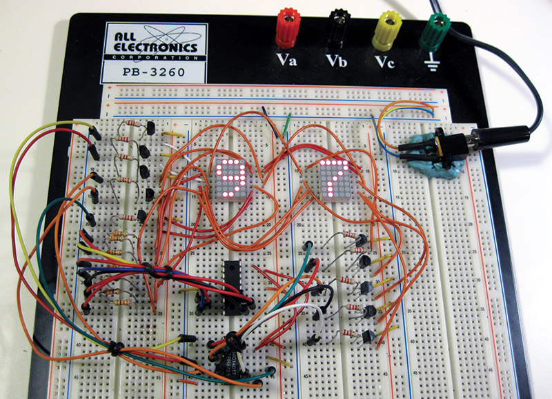
FIGURE 6.
At first blush, you might think this is exceedingly elaborate until you realize there’s actually very few parts there — just a lot of wires. A completed project on a printed circuit board would appear far less busy.
A Two-Digit Horizontal Design
If all you need is the ability to show two digits (not alphabetic characters), then here’s a neat trick. Rotate the matrix LED 90 degrees to yield a five-row, seven-column arrangement. Then, think of the display as being partitioned into a pair of three by five matrices separated by a blank column. See Figure 7 for the details.
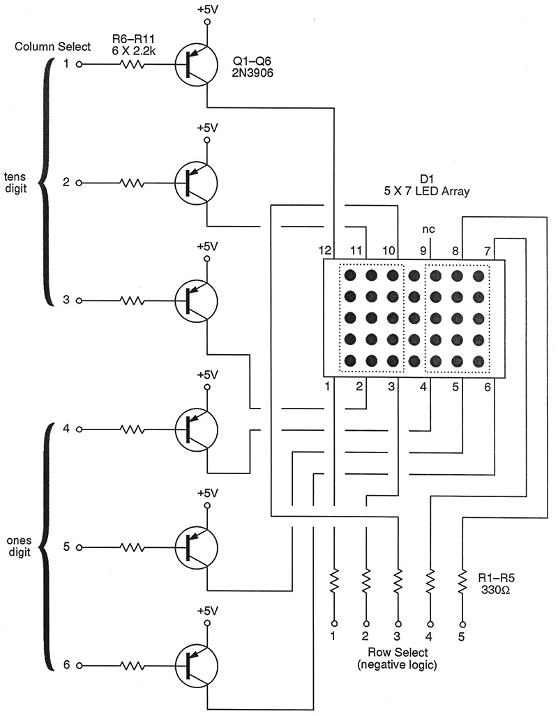
FIGURE 7. Drive this horizontal two-digit display with the PIC circuit of Figure 3, swapping the row and column labels. Now, port A controls the rows and port B controls the columns; pin 12 of the PIC is not needed.
Since we’ve flipped the orientation, the logic changes somewhat. In particular, the columns which become the common anodes must now be driven by PNP transistors and the newly christened row select lines are made active by grounding them. In short, negative logic is now the name of the game. That’s the sort of thing microcontrollers are well suited for sorting out.
We’ll still use the PIC circuitry of Figure 3, but simply exchange the “row” and “column” labels. Note, too, that pin 12 of the PIC has been freed up, since there are only six columns to drive now. It shouldn’t take you more than several minutes to breadboard the revised horizontal arrangement. Figure 8 shows what it looks like.
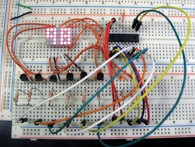
FIGURE 8.
Even though we’ve reduced the resolution, the digits are still eminently readable. Not a bad way of easily attaining a two-digit display. Since negative logic is now in effect, a new set of character bit codes will be required. That’s been taken care of in the software download for this article. Again, refer to the sidebar for the particulars.
What’s Next?
You should now have enough information at your fingertips to whip up some attractive matrix LED displays. Plus, you’ll probably discover other uses and techniques as you play around with the three examples just described. Here are a few ideas to get you going.
Every time you tack on an additional matrix LED, you are — in effect — increasing the number of columns. This implies that each column is now being lit less frequently than before. The net effect is that the entire display may appear somewhat dimmer. One way to bring the brightness back up would be to decrease the value of the current-limiting resistors somewhat. This is actually fairly safe from the point of view of both the PIC and LEDs since the latter are only being pushed for the brief period they’re actually on.
Another possibility is to play with the multiplexing frequency in software. In the three examples described here, the firmware updates the characters about 195 times per second, which is high enough to be free of flicker. Feel free to try other timing values and see what you get. Custom characters are a snap. If you’re using a PIC16F88 like I am, then there’s oodles of room left over in program memory to hold additional character sets. Look over the source code files to see how the standard characters are stored, and then feel free to whip up some new ones.
As for animation, the sky is the limit. Why not see if you can implement a scrolling effect on your own; all it takes is some bit-twiddling. How about an exploding or dissolving character? You might even want to see if you can make the LED dots trace out a simple oscilloscope-like waveform. You get the idea; once the hardware is in place, you can have a heyday with the firmware and rapidly try out new and exotic ideas!
If you’ve mastered the techniques of this article and are anxious to do even more exotic things, then see the sidebar below which describes additional advanced options. A quick perusal of catalogs and the Web suggests a lot is happening in the world of matrix LEDs. Now, you know the fundamentals and are prepared to take on these bigger challenges. NV
Help — I'm Out of Port Lines!
Matrix LEDs can gobble up microcontroller port lines in short order. For a simple display of one or two characters, the designs described in this article will hold you in good stead. If you really can't spare the pins or want to upgrade to multi-color rigs, here are some options to consider.
One possibility would be to exploit an external serial-in, parallel-out shift register chip like the common 74HC595. As the description suggests, the data which control rows or columns are pumped in serially, and the assembled bit pattern is applied to the LEDs in one fell swoop. Just be sure to watch the current handling capabilities of the chip. A more expensive but elegant approach for these displays would be a dedicated driver like the MAX7219 or MAX7221. These take care of all the matrix decoding requirements, and there's less worry about running out of current to light the LEDs. More importantly, they can be interfaced by the SPI protocol which really frees up the microcontroller pins.
If your goal is simply to get a fancy display up and running as quickly as possible, check out the offerings of Adafruit Industries. You'll find them at adafruit.com. This outfit — which is quite popular among the Arduino crowd — offers an entire series of colorful matrix LED displays which are paired with an I2C interface. This is a two-line protocol which really cuts down on the microcontroller demands.
Best of all, I2C devices are addressable, so you can gang more than one display to create longer messages. Arduino fanatics are very familiar with both SPI and I2C communication, but not so widely known is that Great Cow Basic supports both as well, making these options available to PIC aficionados, too.
Downloads
What’s in the zip?
.GCB Source Code Files