Editor's Note - Since the original publication of this article, some specific part numbers mentioned have become obsolete and difficult to find. Substitutions can be made, however, consider the specs and any commentary to select a usable substitute part.
Biassing G-M Tubes Isn’t So Hard
A Minimal HV Generator Powers a Small Geiger-Müller Tube to Detect Ambient Radiation
Small Geiger-Müller (G-M) tubes make ideal sensors for pocket-sized devices to detect radioactivity. They have a high sensitivity to beta particles and some ability to detect gamma rays. Given a thin (and very fragile) mica window they will also detect alpha particles — most G-M tubes don't.
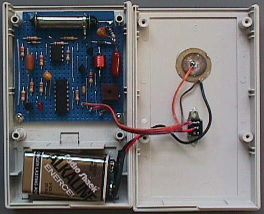
PHOTO 1. Everything fits easily in a small project box. The on/off switch is the only panel control, and above it is glued the piezo element.
Still, even a small G-M tube needs an anode voltage in the 400 to 600 volt region. Here's how to generate that voltage from a 9 V battery. I first used this design in 1979 and I was pleasantly surprised to find that the parts are still available. I've even simplified things by driving the generator with a CMOS 555 timer.
How Much HV?
Reference 1 gives a detailed description of how G-M tubes work. My detector uses a G-M tube 1.5-inches long and 0.3-inches in diameter. Its operating voltage is in the 400 to 500 V region but under normal conditions, it consumes virtually no current. Roughly speaking, each detected particle discharges the capacitance associated with the anode of the tube. Let's assume 450 V and 5 pF — that's 0.5 mJ of energy. At a background rate of one pulse every ten seconds, the mean current is just over 100 picoamps! In practice far more current goes to drive leakage than is needed by the tube. A rectifier with a microamp of reverse current is pretty good by ordinary standards, but would consume several thousand times as much power as the G-M tube! Even measuring the output voltage without drawing a disproportionate current would require a gigohm or so of sensing resistor and a very low bias-current amplifier. Therefore, we are much better off using a fixed-ratio converter and some well-chosen components.
REFERENCE 1.
Detailed G-M tube information.
The (G)Eiger Sanction by Tom Dahlin, Circuit Cellar #150, January 2003
Flyback Fun
In DC-DC converter handbooks, you'll find the flyback converter described as a constant-power device whose output voltage, unless stabilized, varies greatly with the load resistance. Each switching cycle delivers the power stored in an inductor to the load. Either the peak inductor current, or the switching frequency, is adjusted to maintain a constant voltage. What is less well known is that when the load current is low enough, a flyback converter behaves as a constant voltage source. It converts the peak inductor current to output voltage in a ratio that depends only on the inductor and the capacitance associated with it. This transimpedance ratio is the square root of L/C, and with practical components, can exceed 20 kV per amp. A 450 V output, for example, requires a peak inductor current around 20 mA. You can generate a stable high voltage with no transformers or voltage multipliers, just an inductor, a switch transistor, a rectifier and a reservoir capacitor.
A Practical Circuit
Figure 1 shows my implementation of this elegant converter. The CMOS 555 timer (U1) free-runs. Its on-time is about 30 mS, its off-time about 3 mS. The off-time is controlled by an RC network, and the on-time is set by the peak inductor current. The current is adjusted by VR1 to set the output voltage.
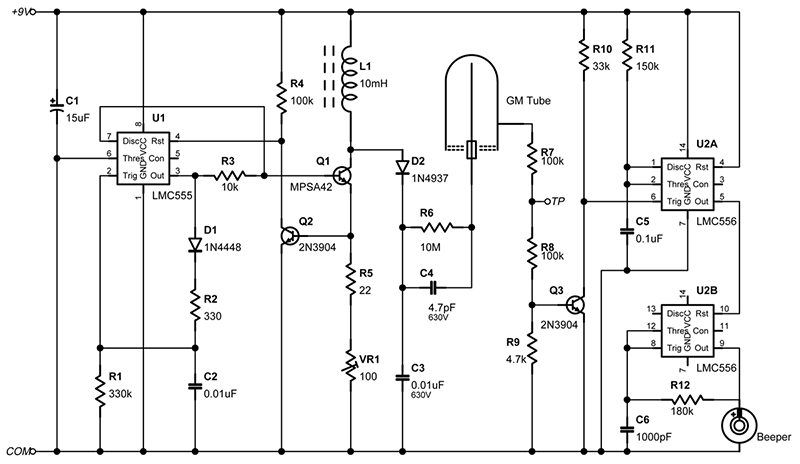
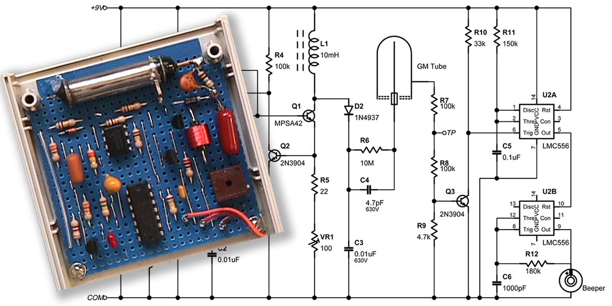
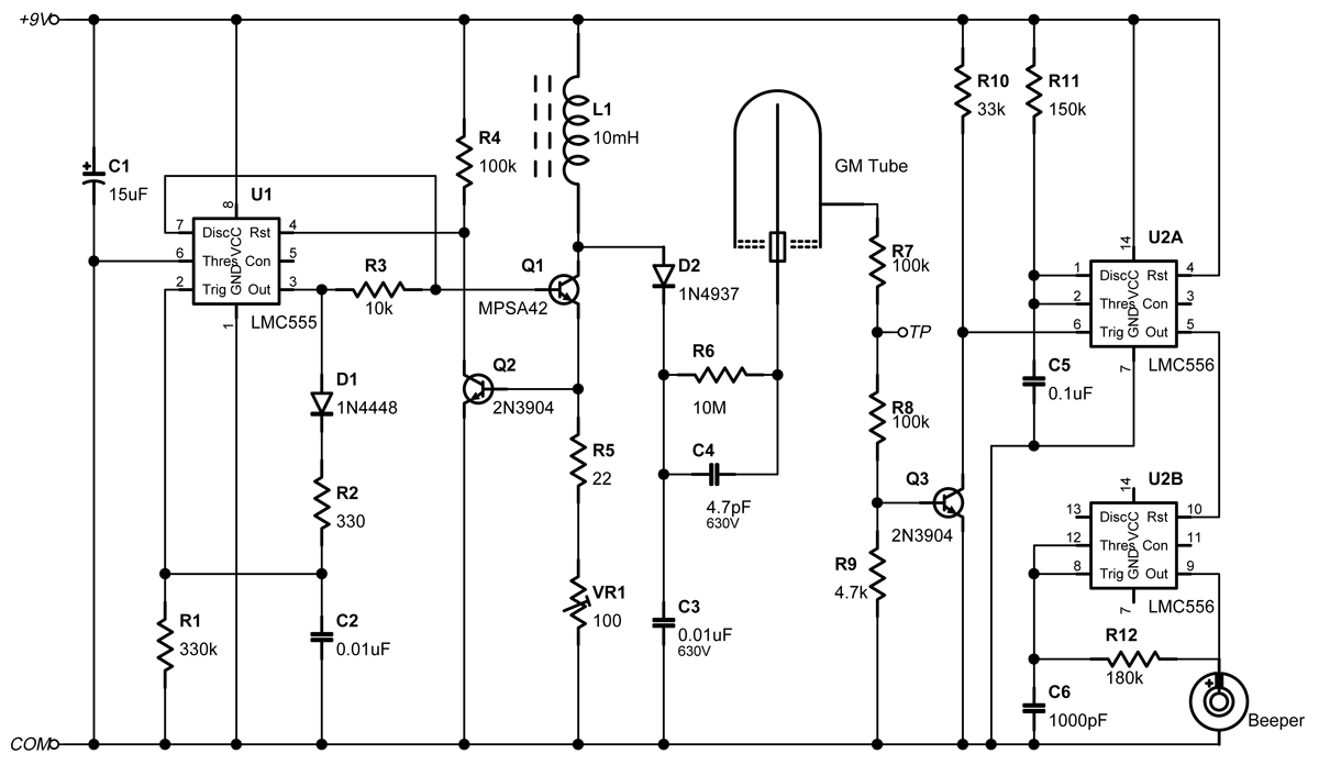
FIGURE 1. Take advantage of that pesky inductive turn-off pulse to power a Geiger-Müller tube. A dual timer makes a beep for every beta or gamma ray detected.
When the theshold current is reached, Q2 resets the 555. C2 then discharges through R1, eventually causing the 555 to retrigger. R1 is chosen to set a pulse rate that supplies sufficient output current while minimizing battery consumption. To avoid temperature drift, C2 should be a stable foil component, not ceramic.
When the output of the timer is high, C2 recharges rapidly via R2 and D1. At the same time, Q1 is turned on, causing the current through it and the inductor to rise by about a milliamp per microsecond. Q2 senses when the current reaches the preset value (around 25 mA).
This resets the timer, its threshold input is unused, and turns Q1 off, creating a positive half-sine-wave spike about 2 mS wide, and over 400 V high at the junction of the transistor and the inductor. D2, a fast high-voltage diode, passes this spike to C3, a 0.01 mF 630 V capacitor, to generate the G-M tube's anode supply. Since the output current is very low, the capacitor voltage remains constant.
The 555's discharge pin clamps Q1's base to ground. This not only achieves a rapid switch-off but also protects Q1 from high voltage breakdown. The negative half-cycle of the inductive spike is clamped via the collector-base diode of Q1.
The output voltage is directly proportional to the peak inductor current and is independent of the battery voltage.
The peak current is stable apart from a slight temperature coefficient so the circuit maintains a constant output without feedback from the output. Besides, G-M tubes are not fussy about their exact supply voltage. Despite the high peak current, the mean load on the battery is about 0.5 mA, giving several hundred hours of use.
Detecting Particles
The anode of the G-M tube is fed via a 10 M resistor, R6. This has a 4.7 pF capacitor (C4, rated at 630 V) across it. When a beta or gamma ray is detected the tube avalanches. The capacitor charges rapidly, dropping the voltage on the tube and giving a rapid quench. As the tube's own capacitance is about 1 pF, C4 defines the charge delivered by the tube.
Each particle detected generates a 5 mS pulse up to 100 V high at the G-M tube's cathode. Two 100K resistors between the cathode and ground protect the counting circuit and provide a protected test point. Q3 turns on for about 3 mS for each pulse. The output pulses drive a 556 dual timer. One half lengthens the pulse to 10 mS and gates the other half, a 3.5 kHz oscillator.
This drives a piezo-electric buzzer, making a beep for each particle. (My buzzer came from a broken calculator but Digi-Key part 102-1126-ND should do.) The pulses on Q3 can also drive a frequency counter to measure the mean radiation level. In my area natural background radiation produces about seven beeps per minute; Colorado residents may get twice that rate.
Radiation Levels
The absolute calibration of the detector depends on the tube size and type, and on the particle type and energy. I calibrated the G-M tube in my original detector with a known Cs137 gamma source. At 100 mRad/H, its count rate was 68 per minute. Since the tube is much more sensitive to beta particles, a given count rate corresponds to a much lower beta dose rate. A high count rate indicates either that something is badly wrong in your neighborhood or that a small source is very close to the tube. The latter, of course, is how you test that everything works.
Distance is important. A source can generate a horrendous dose rate on contact yet, because of the inverse square law, be relatively harmless a few feet away. When my work required handling radioactive sources, my rule of thumb was never to touch one bigger than 10 mCi with my fingers. I used tweezers or tongs instead. Bear in mind that radiation damage is more or less cumulative. (Exactly how much so is still hotly debated.) A source that is harmless in normal use should not be kept in your desk drawer all year.
Putting it Together
The HV generator uses two fairly rare components. One is a dust-cored, wave-wound 10 mH RF choke. The other is an MPSA42, a high-voltage transistor in a TO-92 package. Digi-Key stocks them both as well as the 1N4937 600 V fast recovery rectifier. Don't be tempted to substitute a 1N4005, it's far too slow.
Also stick with the wave-wound inductor, more conventional inductors could have too high a self-capacitance and might break down when generating around 500 V. I used Digi-Key part M7103-ND. HV capacitors are harder to find. If you can't find 630 V parts, 500 V ones should be safe enough. (A 0.5-inch square of double-sided PC board makes an adequate 5 pF HV capacitor.)
The MPSA42 transistor is rated at 300 V but during the HV pulse its base is grounded and the higher, collector-base, breakdown voltage applies.
I don't have the maker's figure for this but testing a sample showed no detectable current below 480 V and only a microamp at 500 V. (Allied Electronics sells the 400 V MPSA44 but I haven't tried it.) In any case the worst that can happen is that the maximum available output voltage will be limited to the transistor's breakdown voltage. You can get a good feel for just how high a pulse voltage you're getting by putting a times-ten scope probe on the collector of Q1. The 15 pF added by the probe reduces the output voltage significantly but its 10 Meg resistance has no effect at all. (Scope probes are usually rated for 600 V input but it would be as well to check.) If you want to measure the output voltage directly you'll need a meter with a better than 100 Meg input resistance.
I've no idea who made my G-M tubes. In 1979 my then boss at CERN, the European accelerator laboratory, was throwing them out and I grabbed them. Similar ones do exist, see Reference 1.
Mechanical Stuff
This project fits a 2.75-inch by 4.6-inch plastic box with a compartment for a nine volt battery (e.g. PacTec HML-9VB). Everything except the buzzer and the on/off switch goes on a small PC board with cutouts to clear the box's molded pillars.
If you cut notches into the bases of the front two pillars and slip the board into them only two screws are needed to lock the board in place. Two #2 nuts glued to the bottom of the case act as stand-offs. The switch and buzzer mount inside the lid. Photo 1 shows the box layout.
For maximum sensitivity the Geiger tube is mounted near the top edge of the box. The detachable end panel of the box should be left off or replaced by thin celluloid, it stops a significant fraction of beta particles.
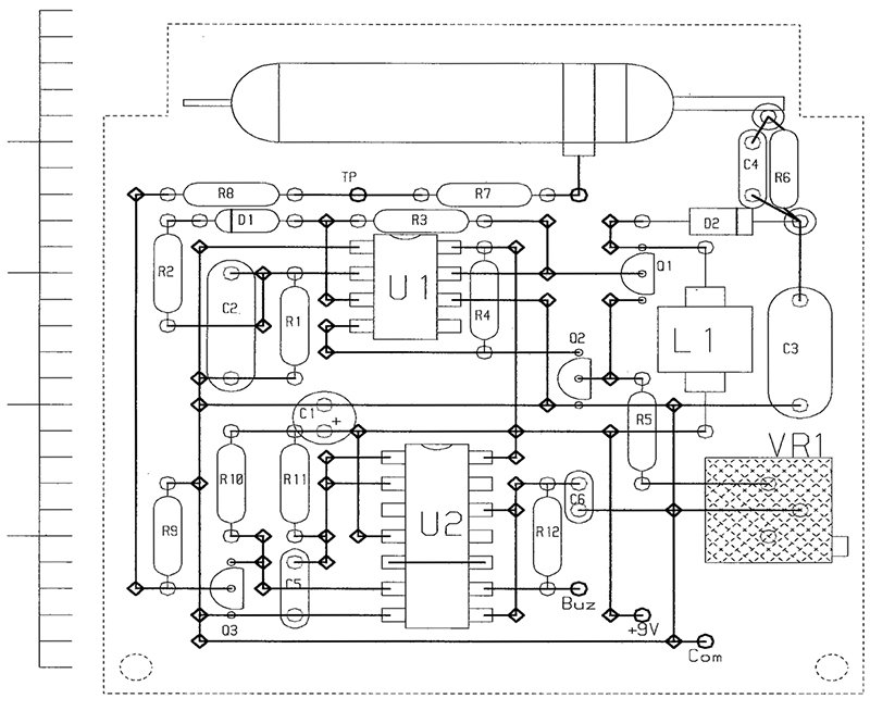
FIGURE 2. The prototype G-M counter was built on a small piece of perf-board whose component side is shown here. Thick vertical lines are bus wires on top of the board, horizontal lines are copper traces on the underside. Diamonds show where a wire connects to the copper.
A socket removed from a female Cannon-D connector slips nicely over the anode pin of the G-M tube. The cathode connection on my G-M tube is a little metal strap. A dab of silicone rubber stops it moving around. Two more tiny dabs on the glass ends of the G-M tube attach it to the board. (Its metal walls are a bit thin to glue to.)
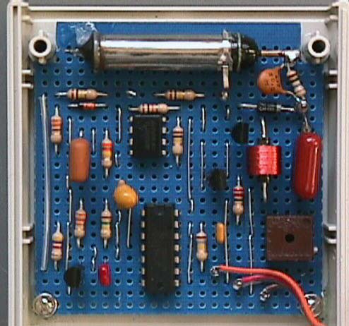
PHOTO 2. A close-up of the prototype constructed on perf-board. The G-M tube fits across the top edge.
Photo 2 and Figure 2 show the board layout. As is my normal practice, I used perforated prototyping board with copper strips on one side.
To cut back on leakage I put two Teflon insulated terminals through the board, one for the tube anode and one for the rectifier cathode. The HV components are wired between them. Even so, the tube voltage wilts on hot humid days.
It's important to keep the stray capacitance at the hot end of the inductor as low as possible. I cut away unneeded copper strips under L1 and D2. Wiring the outside end of the winding to +9 V reduces the effect of capacitance to near-by components.
One connection doesn't show on the board layout, a bus wire on the underside of the board that grounds the unused copper strips under the G-M tube. This stops the HV pulses coupling into the input of the beeper circuit.
Setting Up
The standard way to set the working voltage of a G-M tube is to apply a variable voltage and to plot the counting rate with a radioactive source present.
The plot should show a curve which rises from zero, levels off for a while then starts to rise again. The center of the "plateau" is the optimum operating point. Unfortunately, hanging a voltmeter on the converter takes far more current than the G-M tube.
The alternative is to look at the output pulse (TP in Figure 1) on a scope. If you see variable height pulses around 10 V high you are below the plateau. There the pulse height is proportional to particle energy.
The onset of avalanche is easy to spot. Some pulses will start off small, then suddenly burst out into a much higher pulse.
Adjust the trimmer until all the pulses show a consistent height; with my tubes this was about 12 V. Note this new peak height then adjust the high voltage until the pulses are twice as big, say 25 to 30 V. Table 1 shows the results I found.
One thing to watch is that the voltage changes quite slowly, particularly when adjusting it downwards. Make small trimmer adjustments and wait ten seconds or so for the pulse height to stabilize.
| Pulse height |
Applied voltage |
| 5V |
360 V |
| 10V |
370 V (threshold) |
| 15V |
390 V (above threshold) |
| 20V |
410 V |
| 25V |
440 V (operating point) |
| 30V |
470 V |
| 40V |
525 V |
| 50V |
580 V |
TABLE 1. The output pulse shape varies at the Geiger threshold. A pulse height about twice the threshold level is a good guide to the best operating voltage.
I Name My Sources
Testing G-M tubes is easier if the count rate is higher than background. Small (1 mCi) radioactive sources are available commercially but cost around $75.00 each.
I've used a Wyoming dinosaur bone as a source — they absorbed uranium as they fossilized. My two inch piece of rib generates about four counts per second when placed next to the tube.
If you want to create a stir you could try prowling around your local science store with a Geiger counter checking for "hot" fossils. Other common home-made test sources are objects made from yellow-tinted glass or china-ware with a bright red glaze.
If more than twenty years old these may contain enough uranium to drive most detectors off-scale. Try your local thrift store. My most powerful source is a thirty-year-old packet of colored glaze left over from an attempt at jewelry making.
One interesting experiment is to put a beta source a fixed distance from the G-M tube. Check how the count rate changes as you interpose different thicknesses of aluminum or plexiglass.
A thick enough sheet, about half an inch, will filter out all the betas, leaving only gamma rays. NV
Parts List
| Semiconductors |
| U1 |
LMC555 timer |
| U2 |
LMC556 dual timer |
| Q1 |
MPSA42 high-voltage NPN |
| Q2 |
2N3904 or similar NPN |
| Q3 |
2N3904 or similar NPN |
| D1 |
1N4448 or equivalent |
| D2 |
1N4937 HV, fast-recovery rectifier |
| Passives |
| L1 |
10 mH wave-wound inductor |
| C1 |
15 mF 20 V tantalum bead |
| C2 |
0.01 mF plastic foil |
| C3 |
0.01 mF 630 V |
| C4 |
4.7 pF 630 V |
| C5 |
0.1 mF ceramic |
| C6 |
1000 pF ceramic |
| (All resistors 1/4 W) |
| R1 |
330K |
| R2 |
330Ω |
| R3 |
10K |
| R4 |
100K |
| R5 |
22Ω |
| R6 |
10M |
| R7 |
100K |
| R8 |
100K |
| R9 |
4.7K |
| R10 |
33K |
| R11 |
150K |
| R12 |
180K |
| VR1 |
100Ω ten-turn trimmer |
| Misc. |
| 0.8-inch Piezo buzzer |
| Slide switch |
| Prototyping board |
| Project box |