This article is about the rescue of a high-end multimeter with a faded screen. Once upon a time, OLED (Organic LED) screens were the newest display technology and were going to revolutionize the industry. OLED screens provided superior picture quality and responsiveness compared to LCD screens, while consuming much less power. This made OLED screens a very attractive option for new handheld gaming systems and portable instrumentation systems.
Introduction and Background
Unfortunately, OLED screens have an Achilles heel that LCD screens do not: a limited lifetime and relative fragility of the organic materials. Certain color combinations can burn out the display; prolonged exposure to UV radiation can destroy exposed sections of screens; and OLED screens are inherently less durable than traditional LCD screens because of the materials used. Many products that use OLED displays have screen fading issues, including the multimeter that we rescued with this project.
The multimeter in question is the Agilent U1253B multimeter (Figure 1).
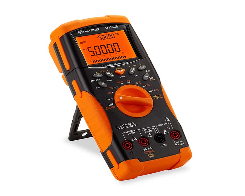
Figure 1 - Agilent U1253B multimeter.
With a $719 price tag, it’s a high-end device with impressive functionality and — aside from a non-functional screen — is essentially in mint condition. The U1253B, in addition to traditional multimeter functionality, has a built-in square wave generator and battery charging capabilities. The price tag and functionality of the device makes the prospect of replacing the multimeter problematic. Repairing the screen is also an issue, as the device is out of warranty and most “hacks” to solve the issue that can be found on the Internet require physically disassembling the multimeter.
First Steps
A feature that all U1250 series Agilent and Keysight multimeters share is an IR interface (shown in Figure 2) that can be connected to an IR-USB cable.
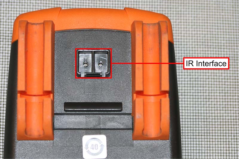
Figure 2 - The IR interface on the back of the Agilent U1253B multimeter.
The cable for the U1253B is called the U1173B, shown in Figure 3.
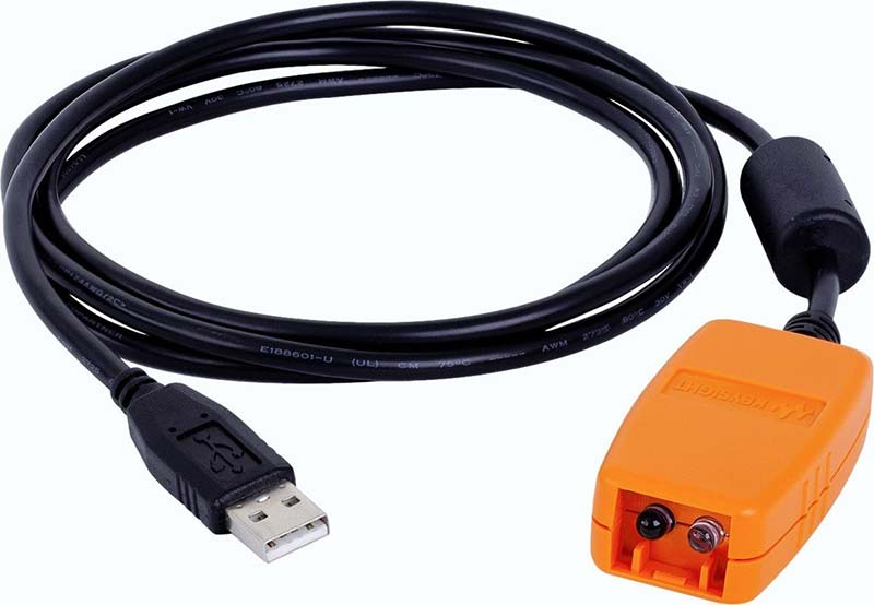
Figure 3 - The U1173B handheld digital multimeter PC connectivity cable.
The U1173B can be connected to a PC as an HID (Human Interface Device) serial device to allow for data collection when a data logger is not readily available. This feature would become the bedrock of the first design.
Using the multimeter as a measurement engine for an ad-hoc PC-based data logger, we effectively side-stepped the need for a display altogether. This worked for a while, but a combination of Windows updates and replaces, not all drivers are updated with it. So, this can make the “fix” unusable as the PC looks for drivers that don’t exist.
The first step towards creating a stand-alone design involved opening an old U1173B. While the inner workings of the device weren’t entirely clear, we were able to determine that the IR communication used two dedicated channels for transmitting and receiving data.
Through experimentation, we were able to ascertain which channel was the transmission channel and which channel was the receiving channel. The data that we observed from the transmission channel were square waves and through some Internet research, we were able to determine that it was sending serial SCPI commands.
Circuit Description
The IR communication circuit, as shown in Figure 4, consists of an eight-pin IC, an IR diode, 200Ω current-limiting resistor, 1 kΩ pull-up resistor, and phototransistor.
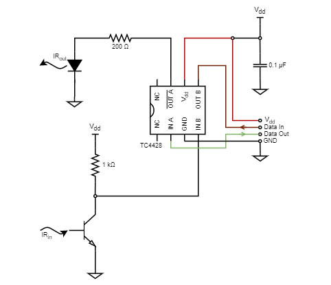
Figure 4 - The IR communication circuit diagram.
The IC is the TC4428A 1.5A dual high-speed power MOSFET driver. The TC4428A is an eight-pin, dual in-line package, with two channels (A and B); one inverting and one non-intervening, respectively. The driver is powered from pins 3 (GND) and 6 (VDD). The TC4428A is used to provide crisp, clean, 0-VDD square wave signals. The output of channel A drives an IR diode through a 200Ω current-limiting resistor. The specific IR diode is not important and almost any IR diode will probably work.
The IR pulses are received by the IR interface on the back of the multimeter. The pulses from the multimeter are received by an IR phototransistor with a 1 kΩ pull-up resistor. The collector of the phototransistor is connected to the input of channel B. Central to the function of this device is that we use a phototransistor, not a photodiode. While the phototransistor resembles an IR photodiode, it’s a hundred times more sensitive.
As with the IR diode, any IR phototransistor will probably work. The particular phototransistor we used in our build resembles a black LED, as it has IR filtering. The 0.1 μF capacitor on VDD is a decoupling capacitor.
We rebuilt the old adapter on a perfboard to fit in the old casing, based on our design shown in Figure 5.
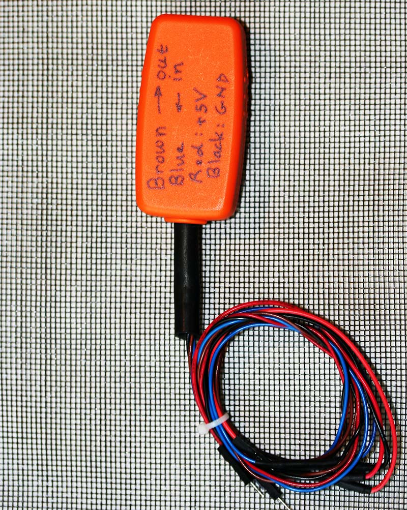
Figure 5a - Rebuilt U1173B, exterior.
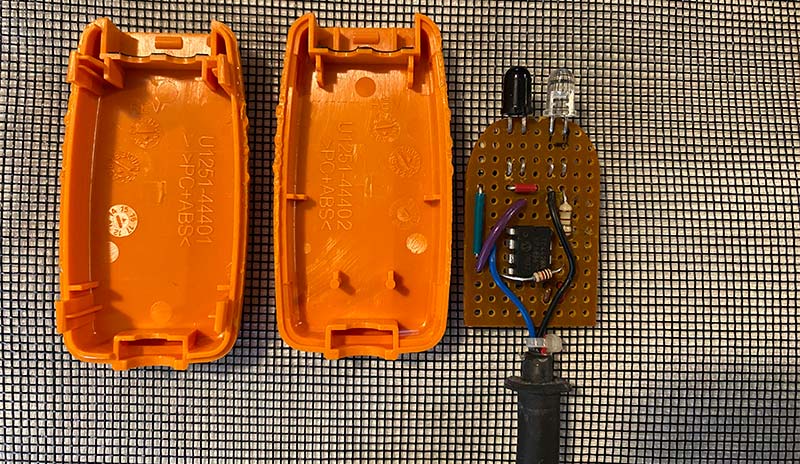
Figure 5b - Rebuilt U1173B, interior.
With this built, we were able to communicate with the multimeter and access the functionality of the device via a serial terminal or script, independent of driver software.
Going Further
At this point, our project was essentially complete. We had rescued the multimeter and bypassed both the need for a screen and driver software. As successful as the first version of the project was, it was also a quick build. The second iteration of the design, shown in Figure 6, was a more involved project.
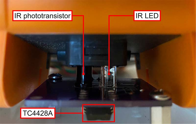
Figure 6 - The second iteration of the project.
Built on an acrylic base, the second version consists of a PCB (printed circuit board), perfboard, and Arduino. The base has a cradle with screws for mounting and securing the multimeter. In the top center of the cradle is a PCB for the adapter circuit with a Molex KK connector. The layout of the PCB is somewhat unique, with the majority of components mounted on the underside of the board (Figure 7).
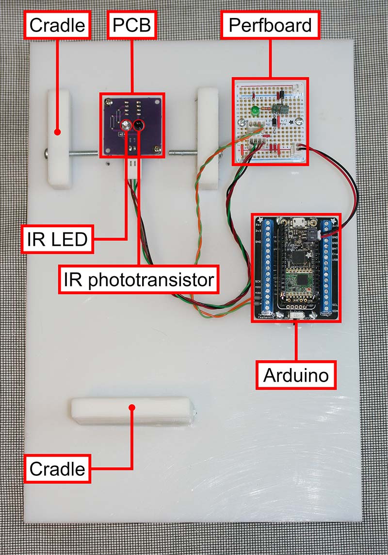
Figure 7 - A close-up of the IR interface, with the U1253B mounted. Note the location of the TC4228A.
The spacing of the IR diode and IR phototransistor was essential to allow the multimeter to properly connect with the IR interface, and by placing most of the components on the reverse of the board, we were afforded a greater degree of precision for design. If desired, a TTL to RS-232 level converter like the cable assembly shown in Figure 8 can be used to communicate with the multimeter directly, instead of using the Arduino.
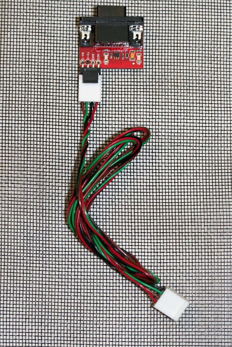
Figure 8 - TTL to RS-232 level converter cable assembly.
The Arduino used in our design is the AdaFruit M0 Feather with a DS3231 FeatherWing add-on (Figure 9).
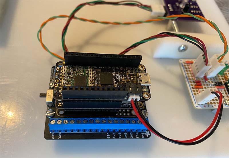
Figure 9 - AdaFruit M0 Feather with DS3231 FeatherWing add-on.
The M0 was chosen as it has a built-in radio that, while unused in the current iteration of the project, may be used for wireless communication in the future. The M0 also features a micro-USB, which is the primary connection to the PC.
The DS3231 features a built-in RTC and an SD card reader — a combination that allows for data logging with timestamps. The M0/DS3231 combination is mounted on the Terminal Block FeatherWing, for both ease of access to the pins of the M0 and mounting purposes.
Finally, the perfboard functions as a central connection hub for the project. As shown in Figure 10, the perfboard has four Molex KK connectors, a green LED, two diodes, a Pololu 2121 reg11a S10V4F5 DC-to-DC converter/regulator, and a resistor.
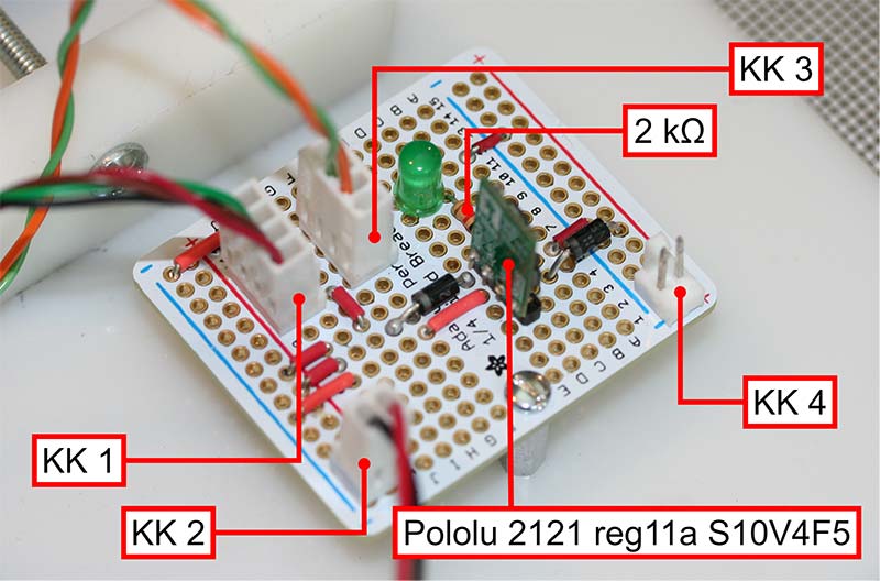
Figure 10 - Central connection hub.
Connectors KK1 and KK2 act as jumpers between the RX and TX of the M0 and PCB.
The 2121 allows for the system to be powered from an external power source, producing 5V from input voltages between 2.5V and 18V. The input of the 2121 is connected to connector KK1 through a diode to prevent power conflicts between the USB connection of the M0 and the perfboard, with the green LED acting as a power-on indicator. Connector KK3 provides power to the M0 from the 5V provided by the 2121.
Software
Much like the hardware of our design, we have two major software versions. Initially, we used Python to send commands to the U1253B, treating it as a measurement engine -- similar to the use of an Arduino as a data logger in the two-part article, “Adventures in Battery-Land” by Edward Andrews. Although the U1253B multimeter supports a full library of SCPI commands, we only use two commands in our design: “FETC?” and “*IDN.” The other commands can be found at sigrok, the primary reference for the software portion of the project.
An example Python script is shown below:
import serial
import time
#Set Up
ser = serial.Serial()
ser.baudrate = 9600
ser.port = ‘COM1’
serial.bytesize = serial.EIGHTBITS
ser.parity = serial.PARITY_NONE
ser.stopbits = serial.STOPBITS_ONE
ser.rtscts = bool(False) # Flow Control
ser.x0nx0ff = bool(False)
ser.dsrdtr = bool(False)
ser.timeout = 1 # Wait up to 1s for response from port
ser.open() # Open the serial port
print(‘Opening Serial Port’)
ser.write(‘*IDN?\n’.encode())# SCPI IDeNtification command
print(ser.readline())
ser.write(‘FETC?\n’.encode())# SCPI FETCh command
print(ser.readline())
time.sleep(2) # Wait 2s
print(‘Closing Serial Port’)
ser.close()
Our second iteration uses a command shell built in the Arduino instead of Python scripts. As with the first iteration, while the U1253B supports a full library of commands, we only use the “FETC?” and “*IDN” commands. (Arduino code is available in the article downloads.)
Conclusion and Future Plans
In this article, we described a project to extend the life of a multimeter with a faded OLED screen. The motivation was that the multimeter itself was both functional — save for the screen — and expensive. The initial design was a reverse-engineered U1253B, designed to be driver-independent.
The current version has extended functionality outside of bypassing a faded screen. Using an Arduino to send serial commands to the multimeter, we have created a multimeter-based data logging system, with the multimeter functioning as a high-end measurement engine.
As stated earlier, a common feature shared by all U1250 series Agilent and Keysight multimeters is an IR interface. Many U1250 multimeters also share the same or similar form-factor. This means that, while the project was designed for the U1253B, the cradle can accommodate other Keysight U12 multimeters. This feature, together with the on-board radio of the M0, allows for both automation and remote data logging that is not possible using a multimeter alone. NV
SCPI (Standard Commands for Programmable Instruments) is an ASCII-based protocol for communicating with instruments. Although released in 1990 for the IEEE 488 bus, it doesn’t define the physical hardware communications link, which means that it can be used with RS-232 and USB.
SCPI commands are either query or set commands, with query commands ending in a question mark (?). SCPI commands use a “tree” structure, with subcommands nested with a colon (:), e.g., the command “measure a DC voltage” would be “MEAS:VOLT:DC?.” Commands that are preceded with an asterisk (*) are called “common commands” and are device-independent. Common commands do not use the tree structure.
Downloads
What’s In The Zip?
Code Files
Schematic
PCB File