Let’s take a close look at signal generators. These devices are used to make the signals used in testing and troubleshooting of radio receivers and other circuits, so are of primary interest to almost everyone interested in electronics.
In the pages of Nuts & Volts, you will find advertisements for used and new signal generators. You can pick up really sweet signal generators of older style technology for a real song, if you’re lucky.
Signal Sources and Signal Generators
Signal generators and signal sources are instruments that generate controlled signals for use in testing and measurement. There is a distinction made by some people between signal sources and signal generators. The former produce continuous wave (CW) output signals without modulation, while the latter will produce one or more forms of modulated signal (AM, FM, SSB, PM) in addition to CW output. In many cases, however, you will see the words “source” and “generator” used interchangeably in popular usage.
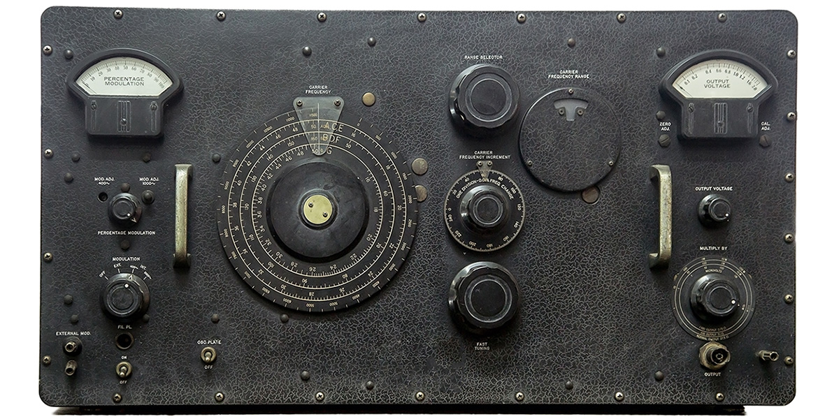
Some signal sources produce a single output frequency (or a discrete number of fixed output frequencies). These instruments are sometimes used for testing channelized receiver systems. Other signal sources will produce outputs over a very wide range of frequencies. Add a modulator stage to these instruments and a signal generator is created. Figure 1 shows a typical commercial signal generator.
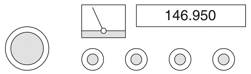
FIGURE 1.
Grades of Instrument
Signal generators and sources come in several grades. Which to select depends on the use. A service grade instrument is used for troubleshooting common broadcast band receivers. They often lack a calibrated or metered output level control, and the frequency accuracy is usually low. More importantly, for many sensitive measurements at low output levels, more signal will escape around the flanges than comes through the output connector. Such instruments are useful for simple troubleshooting, but useless for accurate measurements.
Laboratory grade signal sources and generators are very high quality instruments with accurate frequency readout and output level controls. These instruments are used in making lab measurements of receivers and other devices where high precision and accuracy is desired.
Quality service grade instruments fall somewhere between the two previous grades. Several mainline manufacturers of high quality laboratory signal sources and generators also manufacture “economy” lines that fit this category. They are considerably higher grade than the simple service instruments, but are not up to the lab grade. They are often used for troubleshooting high quality telecommunications and landmobile systems where the highly accurate and precise measurements are not needed.
Output Level
The output of a calibrated signal generator is usually expressed in either microvolts (µV) or dBm (decibels relative to one milliwatt in 50 ohms), or both µV and dBm. It is useful to have a feel for both forms of output level indication. One microvolt (1 µV) is 10-6 volts, so when applied across a 50-ohm resistive load, produces a power level of
V2/R = (10-6 V)2/(50 Ω) = 2 x 10-14 watts
The 0 dBm reference level is one milliwatt (1-mW) dissipated in a 50-ohm resistive load. This represents an applied voltage of

If the output level set dial on a particular instrument is not calibrated in the correct units, then the required unit can be calculated using these methods.
To find the output power level in watts or milliwatts from dBm is similarly simple:
P = 10dBm/10 milliwatts
To find the level in watts divide Equation (3) by 1000.
Output Signal Quality
It would be nice if all signal sources and signal generators were ideal, i.e., the output frequency and output level are noiseless and perfectly calibrated. That never occurs, although the differences in these specifications is a principal difference between high and low quality instruments.
Frequency
The important considerations regarding frequency are the range, resolution, accuracy, and (in automatic test equipment applications) the switching speed.
Range. The frequency range is a specification that tells the specific frequencies that are covered. In some cases, there will be only one frequency, or some small number of discrete frequencies. In other cases, one or more bands of frequencies are provided.
Resolution. The resolution is the statement of the smallest increment of frequency that can be set. On analog instruments that do not have a counter, the resolution is poor. The resolution may (but not certainly) be improved by adding a digital frequency counter to measure the output frequency. On modern synthesizers, it is possible to set frequency with extremely good resolution.
Accuracy. This specification refers to how nearly the actual output frequency matches the set frequency. The accuracy is a function of the set frequency (and how closely it can be set), FSet, long-term aging (taging) and the time since last calibration (tcal). Mathematically:
Accuracy = ± FSet x tAging x tCal
Example
A signal generator is set to 480 MHz, and has an aging rate of 0.155 ppm/year. It has been six months (0.5 year) since the last calibration.
Accuracy = ± FSet x tAging x tCal
Accuracy = ± (480 MHz) x (0.155 ppm/year) x (0.5 year)
Accuracy = ± 37.2 Hz
There may also be some random variation in the output frequency. Figure 2 shows the uncertainty band around the set frequency.
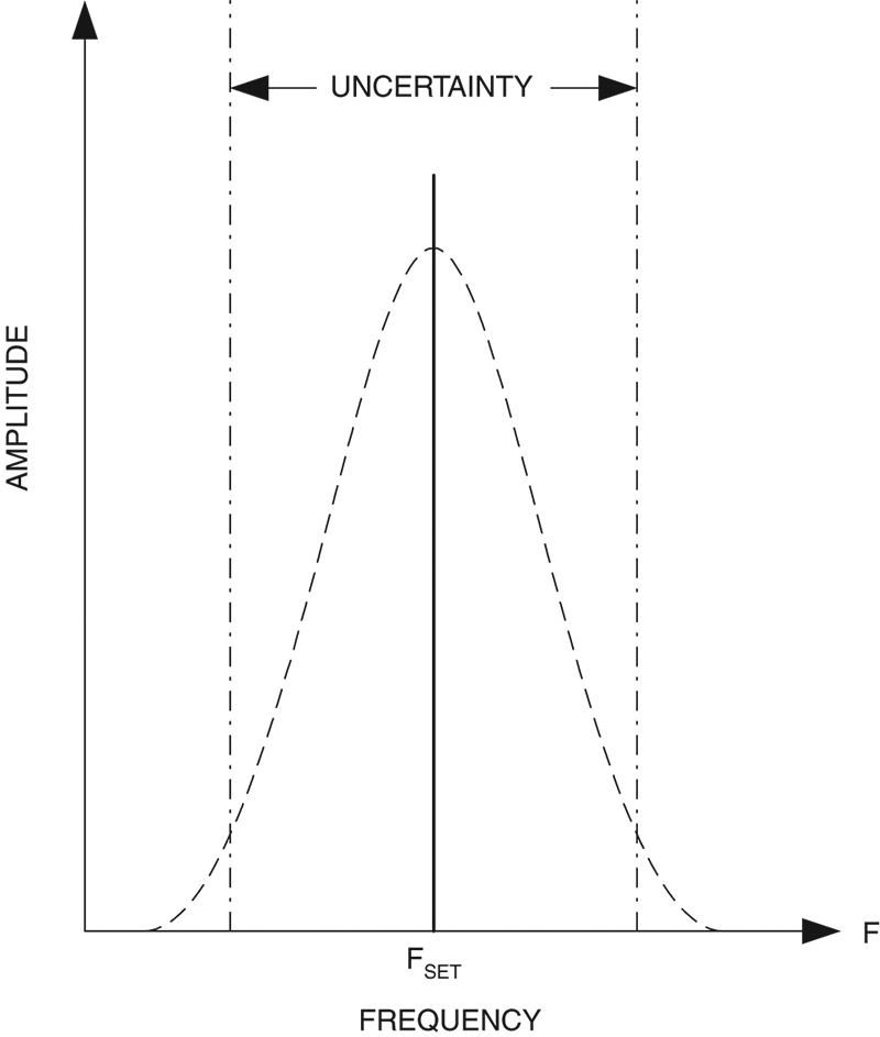
FIGURE 2.
The actual output frequency, Fo, will be FSet ± Accuracy. It is the general practice to calibrate a signal generator on six-month or annual schedules, depending on the use.
Switching Speed (Settling Time). This is the length of time, usually in milliseconds or microseconds, that is required for a synthesized signal source or generator to move to a new frequency when digitally commanded to change. It is calculated as the length of time for the error of the frequency and/or output level commanded by the change to come into specification range.
Output Level
The output level can be expressed in either voltage, power, or dBm notations. All are equivalent, although one or the other will be preferred in most cases. The most common method of describing the output level is dBm. A typical signal generator or CW signal source will produce output levels from -136 dBm to +10 dbm (some go to higher levels), with an output level accuracy of ±0.50 dBm and a resolution of 0.01 to 0.02 dB.
As with frequency, there are factors that affect the accuracy of the actual output vs. the set output. Figure 3 shows that there is a zone of uncertainty around the output level set.
FIGURE 3.
For any given setting, there are Pmin and PMax values. For example, if the only error is the accuracy discussed above (e.g., 0.50 dB), a level set of, say, -10 dBm will produce an actual output power level of -9.5 to -10.5 dBm.
Spectral Purity
The output signal is not always nice and clean. Although the purity of the output signal is one of the distinguishing factors that differentiate lower quality and higher quality generators, they all produce signals other than the one desired. Figure 4A shows a typical spectrum output.
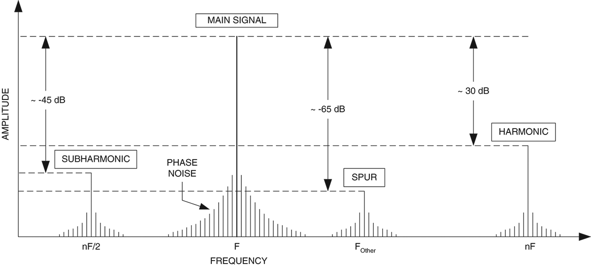
FIGURE 4A.
This display is what might be seen on a spectrum analyzer. The main signal is a CW sinewave so, ideally, we would expect only one single spike with a height proportional to the output level. But there are a lot of other signals present.
First, note that the main signal is spread out by phase noise. This noise is random variation around the main frequency. When integrated over a specified bandwidth, e.g., 300 to 3,000 Hz, the phase noise is called residual FM (Figure 4B).
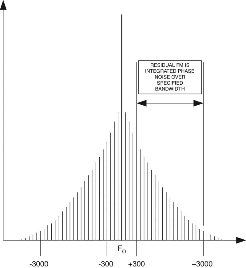
FIGURE 4B.
Second, there are harmonics present in Figure 4A. If the main signal has a frequency of F, the harmonics have frequencies of nF, where n is an integer. For example, the second harmonic is 2F, and the third harmonic is 3F. In many cases, the 3F harmonic is stronger than the 2F harmonic, although, in general, the higher harmonics are weaker than lower harmonics.
There are also sometimes sub-harmonics. These are integer quotients of the main signal. Again, if the F is the main signal frequency, nF/2 represents the sub-harmonics. Typically, unless something is interfering with the output signal, sub-harmonics are not as prominent. One thing that does make sub-harmonics prominent, however, is the use of frequency multiplier or divider stages (which is the case in many modern generators).
Finally, there are miscellaneous spurious signals (“spurs”) found on some generators. These might be due to power supply ripple modulating the output signal, parasitic oscillations, digital noise from counter or phase locked loop circuits, and other sources.
Harmonics and spurs are usually measured in terms of decibels below the carrier (dBc), where the carrier is the amplitude of the main output signal. In general, the lower the unwanted components are, the better the signal source.
Phase noise warrants some special consideration. It is usually measured in terms of dBc/Hz, i.e., decibels below the carrier per Hertz of bandwidth. This noise is concentrated around the main signal frequency, and is normally graphed on a log-log scale to permit both close-in and further-out noise components to be compressed on one graph.
Architectures
Although there are many different configurations, with different “block diagram” representations, there are only a few different architectures used in designing signal generators. Figure 5 shows a simple analog architecture that was once common on even high-grade instruments, and is still common on service grade instruments.
The signal is generated in an L-C controlled variable frequency oscillator (VFO). The VFO typically has a bandswitch for selecting different frequency ranges. A calibrated tuning dial gives the user an approximate idea of the output frequency. However, because of drift and the mechanical aspects of calibrating the dial, these dials are not terribly accurate.
Some instruments have an output amplifier although, for many decades, even quality signal generators lacked power amplifiers. The output of the VFO was fed directly to the output level control.
Service grade generators of this architecture usually have a crude form of output level control. Higher quality instruments, on the other hand, will have some variant of the output circuit shown in Figure 5.
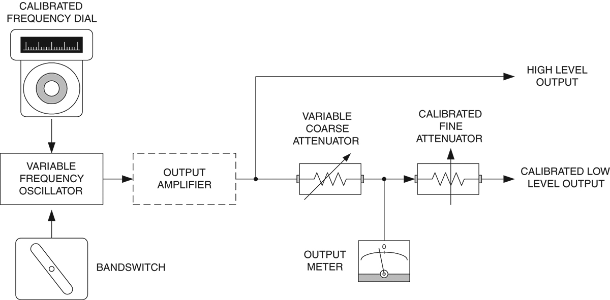
FIGURE 5.
A high level output is sometimes provided to permit the user to route the signal to a frequency counter so that an accurate determination of frequency can be achieved.
There are two attenuators in the output level setting circuit. A coarse attenuator is used to set a relative output meter to some calibrated point. In most cases, the meter would be calibrated with a zero in the center of the analog scale. The coarse attenuator is adjusted to center the meter pointer over the zero point in the center of the meter. When this is done, the settings of the fine output attenuator are valid.
Other Types of Signal Generators
In the main, this article is about RF signal generators. But there are two other types of signal generators that have to be accounted for. First, there is the straight audio signal generator. Second, there is the function generator. The audio signal generator will produce a high quality sinewave output, and possibly also a squarewave output. It will possibly offer a precision output control, either by metering or by dial. These signal generators universally have a 600-ohm output. What is also true is that they rarely cover more than the audio frequencies (20 Hz to 20 KHz), although a few go to 100 KHz. Function generators, on the other hand, may go to 1 MHz or 2 MHz for common grades, to over 20 MHz in some grades.
Function generators differ from straight audio generators in that they have three or more functions: sine-, square-, and trianglewaves. They usually have multiple outputs, or are switch-selectable between 50 ohms, 600 ohms, and TTL output. The typical function generator also differs from the audio generator in that the output control is rather crude being a single knob control.
British Boatanchors
A “boatanchor” is a radio that glows in the dark, i.e., a vacuum tube radio. In the United States today there are a number of boatanchor collectors. While in the United Kingdom, I had the opportunity to visit a London-area based boatanchor museum during a boatanchor event.
It was interesting to see the differences in design philosophy between American and UK based designers. Most of the radios were of the superheterodyne design, but that is where the similarity ends. The cabinetry of the UK designs look different from American cabinetry (including a few “round” radios!). Other than that, the shape factors of the radios were different from typical American designs.
Speaking of boatanchors, I am a fan of the Hallicrafters SX-28A “Super Skyride” model. There is a web site devoted to the SX-28: www.qsl.net/wa2whv/hallicrafters.html. Go take a look at it if you are so inclined.
Next time...
Next time, we will talk about frequency synthesizers — the king of signal generators — as well as several other topics applicable to all high quality signal generators. NV