This is a “for fun and experimentation” project and is not intended to offer medical advice whatsoever.
Operating an armed military drone half way around the world is not only a complex task, but allows for no margin for error. Lives are quite literally on the line. The training of drone operators is necessarily in depth and intense. Faced with the problem of training personnel quickly enough, DARPA (Defense Advanced Research Projects Agency) decided to try an absolutely extraordinary approach ...
Seizing on recent exciting research in neurostimulation using transcranial direct current stimulation (tDCS), DARPA scientists attached salt water electrodes to the temple and left shoulder of drone operator trainees. After passing very small direct currents of a few milliamps through the electrodes, scientists were “shocked” to find that new pilots attained the skills needed to pilot the drones in half the time normally required.
The results were so striking that extensive double blind testing followed using “sham” currents and control groups, only to find the same results.
Though the idea of using small DC voltages for brain stimulation is more than 100 years old, the immense publicity from the well controlled DARPA experiment and the simplicity of the design has led to a great deal of both professional and amateur interest.
I was first introduced to the idea by a friend who had been treated for major depression using just such a tDCS machine. His observation was that though he did not feel as if his problems had gone away, he said it was “as if a net that had been dragging him down had been removed after the treatment,” allowing him to get on his feet again and deal with his life positively.
Many studies show encouraging results for decreasing anxiety, addiction, lessening depression, and even increasing concentration.
The actual circuitry needed to make a working tDCS unit is almost frighteningly simple.
In fact, from a strictly circuitry standpoint, it qualifies as one of those great “evening projects” we all love.
However, even though this technology is over 100 years old and every study seems to tout the safety of these tiny currents, I want to emphasize that this is certainly a “fringe” electronic project in every sense!
I am not an expert nor a medical professional, but simply a hobbyist who has had some interesting experiences with this device that I would like to share with you as one of the amazing group of readers of Nuts & Volts. So, proceed with caution!
Another great thing about exploring offbeat topics like tDCS are the many other strange and useful things you always seem to discover along the way! So, don’t be surprised if we take a couple quick detours to project completion.
A Quick Look at the Schematic
All that is required for a working device is that we produce a regulated current of between .5 and 2 mA through a pair of salt water electrodes attached to the skin.
Because skin resistance can vary enormously from person to person (I’ve measured resistance between the electrodes of anywhere from 1.5K to 5K with different people), a minimum voltage of approximately nine volts is needed (2 mA at 9 volts = 4.5K skin resistance).
Voltage ranges on commercial units run all the way from nine volts to 18 volts and more.
In what is strictly my personal opinion, anything below six volts seems to produce no effect, and above 12 volts can occasionally lead to skin irritation (if used with smaller electrodes).
For our schematic, I wanted to power this device directly from a cell phone for convenience, or even with an inexpensive rechargeable cell. So, I thought it would be particularly useful to get power from a USB port connection. Figure 1 shows a USB cable and suitable case.
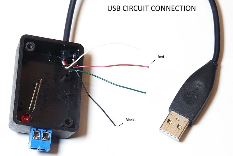
Figure 1.
Important Note: Never power any tDCS unit from a device that connects — even indirectly — to line current under any circumstances.
The basic schematic is shown in Figure 2 and uses a simple 7660 voltage converter (configured as a voltage doubler with the diode and cap multiplier).
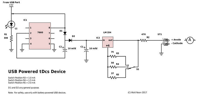
Figure 2.
The output of the converter is coupled to an LM334 voltage regulator.
Three switched positions allow selection of approximately .5, 1.5, and 2 mA settings.
In this configuration, the 7660 will boost the five volt USB output to approximately 11.5 volts to overcome skin resistance, and the LM334 will then limit current to between .5 and 2 mA, depending on the feedback resistor.
If you are making a scrap drawer assembly and don’t happen to have an LM334, it's important to make certain that the voltage regulator you use is stable at very small currents of less than 2 mA. Figure 3 shows the simple completed perfboard assembly.
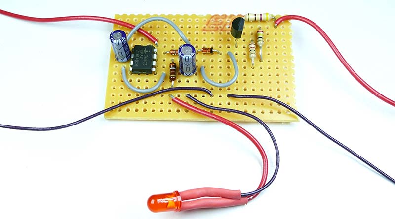
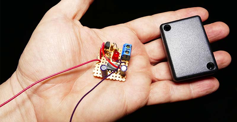
Figure 3.
Note: For experimentation, it’s possible to replace S1 with a single 100 ohm potentiometer connected to R5 if you would like infinite adjustment (within the set range) for your own experimentation.
Last, a simple ammeter can be connected as shown in series with your anode to verify your output for testing. When prototyping my first tDCS, I used the 100 ohm pot mentioned above, and built the ammeter into the case as in Figure 4.
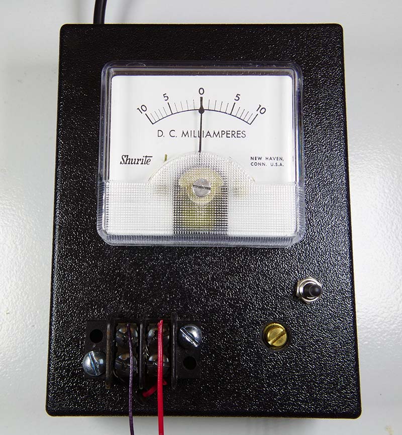
Figure 4.
Making Your Electrodes
Method 1
Figure 5 shows the traditional way electrodes were made for most of the university and military studies I’ve seen.
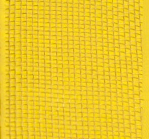
Figure 5.
A simple piece of copper screen is attached (often sewn) to a small clean sponge approximately 1/4” thick. A wire is soldered to the screen, and attached to your tDCS device.
The actual material a sponge is made from is largely unimportant, though a higher density is preferred for best conduction. (A very porous sponge can lead to some skin irritation due to the lack of contact.) Figure 6 shows typical sizing of sponges.
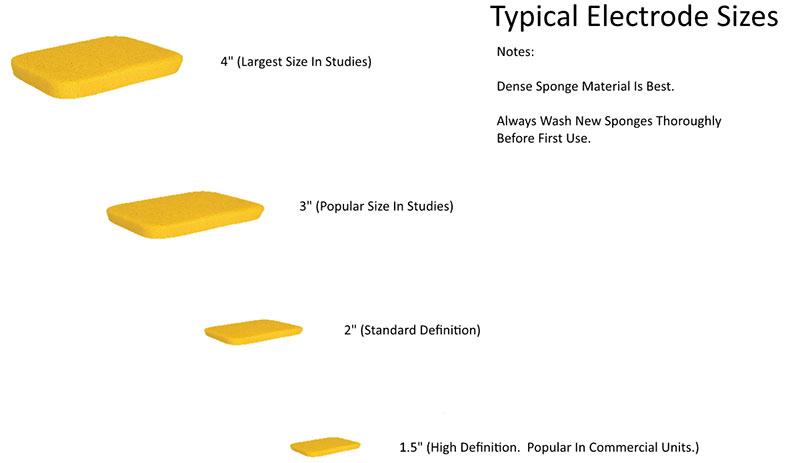
Figure 6.
Method 2
Recently, better commercial units have used smaller (1.5” diameter) sponges in holders that make them easy to clean and replace. Figures 7 and 8 show a simple design that will allow our unit to work the same way.
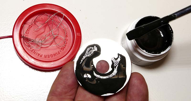
Figure 7.
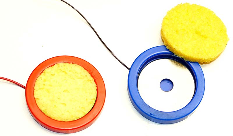
Figure 8.
Using a plastic cap from any jar, a stainless steel fender washer, and some “wire glue,” an excellent sponge/electrode holder can be made. Make certain your plastic cap is at least 1.5” in diameter, and cut a section of sponge 1/4” thick to fit very snugly into the cap.
Strip the insulation from perhaps the last 2” of one of your leads, and feed it into the plastic cap as shown.
Coat one side of a stainless steel or brass washer with wire glue, and press it into the cap until the glue dries. This creates a conductive seat when dry for our sponge to sit on; yet, sponges can be popped in and out easily for cleaning or replacement.
This arrangement would probably work without the wire glue, and a brass washer could certainly have the wire soldered directly in place. However, given the fact that everything will be soaked in salt water, the wire glue and stainless steel washer have proven highly resistant to corrosion.
Figure 9 shows the completed sponge electrodes, and the full unit.
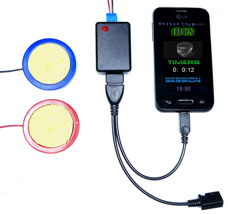
Figure 9.
Method 3
As a quick alternative, you can make a disposable electrode by just using the wire glue to attach the wires and “any old” washer directly to the sponge. Disposable electrodes usually last several months.
You can make a very conductive and durable homemade wire glue by simply mixing a flexible variety such as Goop™ brand glue with graphite. The more graphite you can mix into the glue, the better the conduction (Figure 10).
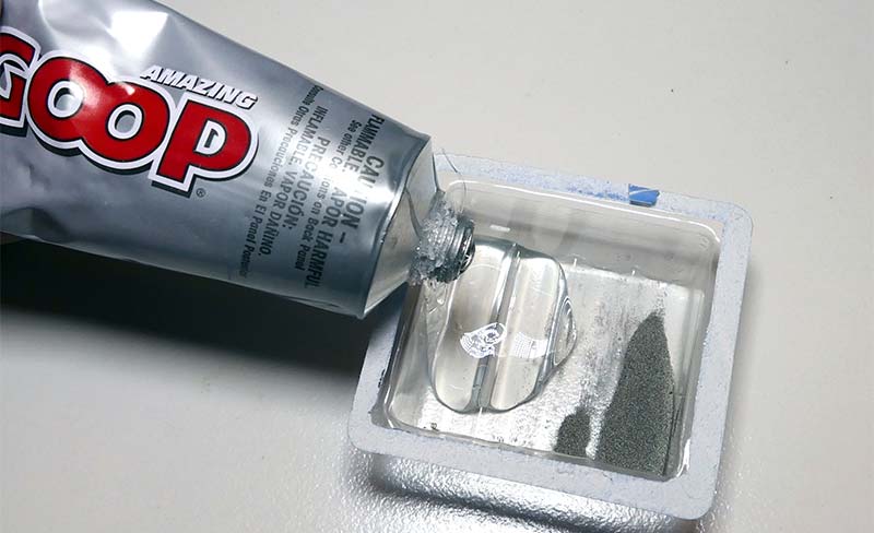
Figure 10.
Important Note: Make absolutely sure to wash new sponges thoroughly before using them the first time. Many supermarket sponges have bleach-like preservatives in them when shipped which can irritate skin! (Don’t ask me how I know.)
The Phone App
Although you could use any battery powered USB (or other) source to power your tDCS, why not use a battery most of us have handy with us all the time: our smartphones! I’ve written a quick free phone app that can be used to time a session, display electrode placements in 3D, and even power a tDCS device directly from your phone. Getting power from your phone’s data port can be useful for many low power electronic projects as well.
The easiest method of getting power from your phone is to use an On The Go (OTG) cable as in Figure 11.
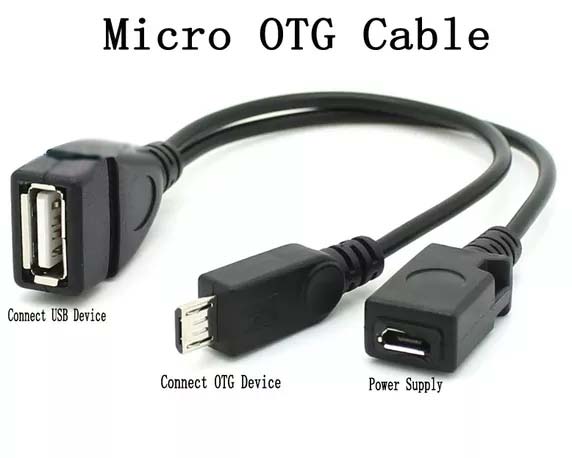
Figure 11.
This is available for both iPhone and Android. By plugging an OTG cable into your phone, you not only get USB functionality, but can also power low current devices like our tDCS circuit (or anything else) directly.
Keep in mind, not all phones are compatible with OTG. However, you can download a free OTG checker for your phone from any app store to make sure it’s compatible.
If your phone is not OTG compatible, you can still power a tDCS circuit very easily from a “power bank” cell phone recharger or any battery powered device with a USB port. Power bank devices are available from Amazon and elsewhere for less than $5. I’ll make the phone app available for anyone who would like it on a special web page for Nuts & Volts readers at noonco.com/tdcsnv.
Electrode Placements and Montages
There are some very spectacular in-depth manuals regarding electrode placement available on the Internet. So, I’ll just cover the topic very briefly here.
In short, electrode positions are found using the International 10/20 system. The numbers ‘10’ and ‘20’ simply refer to the fact that the distances between adjacent electrodes are either 10% or 20% of the total front-back or right-left distance of the skull.
Measurement is made from the nasion which is the point between the forehead and nose, and the inion which is the lowest point of the skull from the back of the head.
Figure 12 shows the distribution of possible positions from that basic measurement.
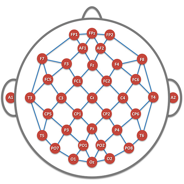
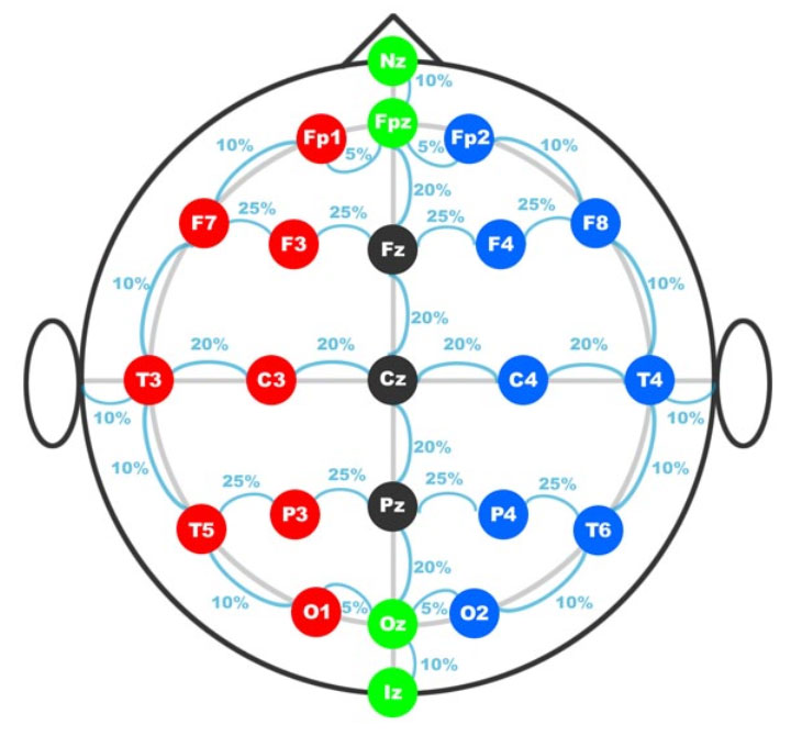
Figure 12.
So, if in your research, an electrode is said to be placed at F3, this measurement and chart will give you an excellent placement reference.
Though I’m sure precision placement is ideal, because electrode coverage areas are large, most people I have spoken to have simply used 3D models already set up to show relative placement. Figure 13 shows three typical placements.

Figure 13.
I feel these three are among the best researched placements, but many more options are available with a quick Internet search.
Typical times for sessions are between 20 and 30 minutes, and can be repeated in 48 hours. Electrodes can be held in place on the head very easily with a couple of women’s hair bands.
I base my evaluation of “is it working” (voltage/electrode position, etc.) on a tiny flash of light (called a phosphene) that is often witnessed just as the device is disconnected. This is a flash of light that is seen only in your mind.
Wrap Up
It’s always a pleasure for me to delve into “strange science,” and I hope it has been for you as well! I tend to be a very skeptical person by nature, but do feel after experimenting with this device, it has been a fascinating and worthwhile project and experience.
I’ve been interested in electric therapies since Dr. Robert Becker’s book, The Body Electric caught my attention just out of high school many years ago. The topic of “electrotherapy” makes for many nights of good reading.
I strongly recommend researching tDCS devices before experimenting if this topic has caught your interest. Many of the stories are wildly interesting and entertaining.
Does it really affect your brain? Or, is this yet another example of the latest fad in placebos?
I certainly have an opinion, but I’ll leave it to you to form your own. NV
| ITEM |
DESCRIPTION |
| R1 |
330 ohm |
| R2 |
470 ohm |
| R3 |
75 ohm |
| R4 |
50 ohm |
| R5 |
37 ohm |
| C1-C2 |
10 mfd electrolytic |
| D1-D2 |
1N4148 (Any general-purpose will do) |
| LED |
Any 1.8-2.2 VDC |
| IC1 |
ICL7660SCPA voltage converter |
| IC2 |
LM334 voltage regulator |
| S1 |
Three-position switch |
| ST1 |
Two-pole terminal block |
| USB Cable |
|
| 26 Ga Stranded hookup wire |
|
| 1.5" Stainless steel fender washers |
|
| Kitchen sponge |
|
| Case |
Hammond 1551GBK (https://www.hammfg.com/part/1551GBK) |
Corrections
I made a small error in the original schematic that I provided Nuts & Volts, in which I showed pin 4 of the 7660 connected to ground. In this configuration, the device is functional, and will put out the minimum voltage required for a good tDCS session.
However, you can choose the higher voltage output recommended in the article by simply moving the ground wire from pin 4 to pin 3 on the 7660. (Pin 4 will be left unconnected.)
A small number of articles detailing tDCS research have indicated that "more is not necessarily better," and that finding the minimum voltage that works for you actually produces stronger results.
So, I've decided to pretend this was a fortuitous error, and mention that you might like to give it a try both ways.
If you do, I hope you'll let us know what you think.
My apologies to the readers of Nuts & Volts for the schematic error.
Downloads
What’s in the zip?
Figure 2 Schematic, Option 2