Crosley Radio Corporation’s 1936 “WLW Model Super-Power Radio Receiver”
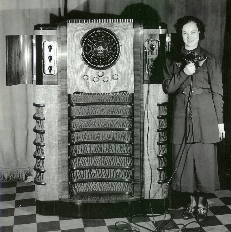
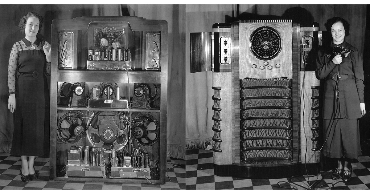
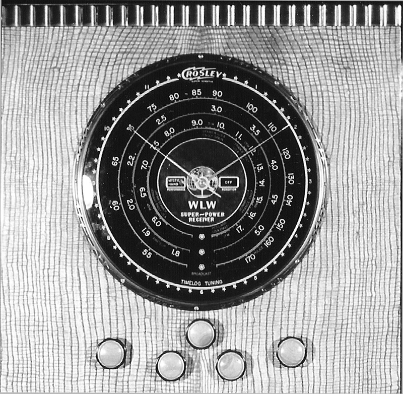
Front of Crosley Radio Corporation’s WLW Model Super-Power radio receiver. Features included multiple tuning, volume, fidelity, and tone controls, as well as a public address system.
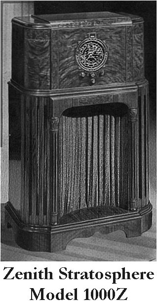
In 1935, the Zenith Radio Corporation produced a stunning radio receiver called the Stratosphere model 1000Z. The set used 25 tubes and three loudspeakers — more than any other radio to date. An amazing (for the time) 50 watts drove its three speakers — one 6 inch dynamic high-frequency and two 12 inch dynamic low-frequency speakers.
Standing 50-1/2 inches tall, the Stratosphere sold for $750.00 — more than many automobiles; in comparison, a new Ford cost $652.00. At that price, it’s no wonder that only about 350 sets were produced during the four years that the Stratosphere was offered.
This achievement impressed Powel Crosley, Jr. — the President of the Crosley Radio Corporation — who praised it as a fine example of quality in radio construction, but it used “only” 25 tubes and three speakers! Crosley — who also owned the 500,000 watt powerhouse radio station, WLW — was inspired to surpass Zenith by bringing the world the largest and most powerful radio receiver yet known.
A close friend of Commander Eugene MacDonald — President of Zenith — Crosley may have taken the Stratosphere as a light-hearted challenge. That aside, Crosley later said, “It is fitting that the owner of the world’s most powerful radio station make the world’s greatest radio receiver.”
Crosley’s engineering and marketing staff urged him to forget the idea. They felt that it was an impractical exercise from an engineering standpoint and that the market for such a radio — if one existed — would be miniscule. Crosley, however, was not easily discouraged and, as one employee put it at the time, “It is characteristic of Mr. Crosley that he is a good salesman — enough so to win his point in an amiable manner.” Of course, the fact that Crosley owned the company had some bearing on the matter.
Surpassing the Zenith Stratosphere turned into a bigger project than anyone had expected. Many engineering conferences were held throughout the winter months, some of which included Crosley’s advertising, sales, accounting, and purchasing departments. To aid with speaker selection and the acoustics involved in cabinet design, the Chief Engineer of the Jensen Radio Manufacturing Company was retained as a consultant; Jensen is the same company that now manufactures speakers.
Out of the numerous meetings and Crosley’s imagination came the basic specifications: the radio would be a superheterodyne receiver with no fewer than 30 tubes, six loudspeakers, four chassis; a suitably impressive cabinet would house it. More intricate than any set ever built, it would naturally have the highest possible quality and richness of tone.
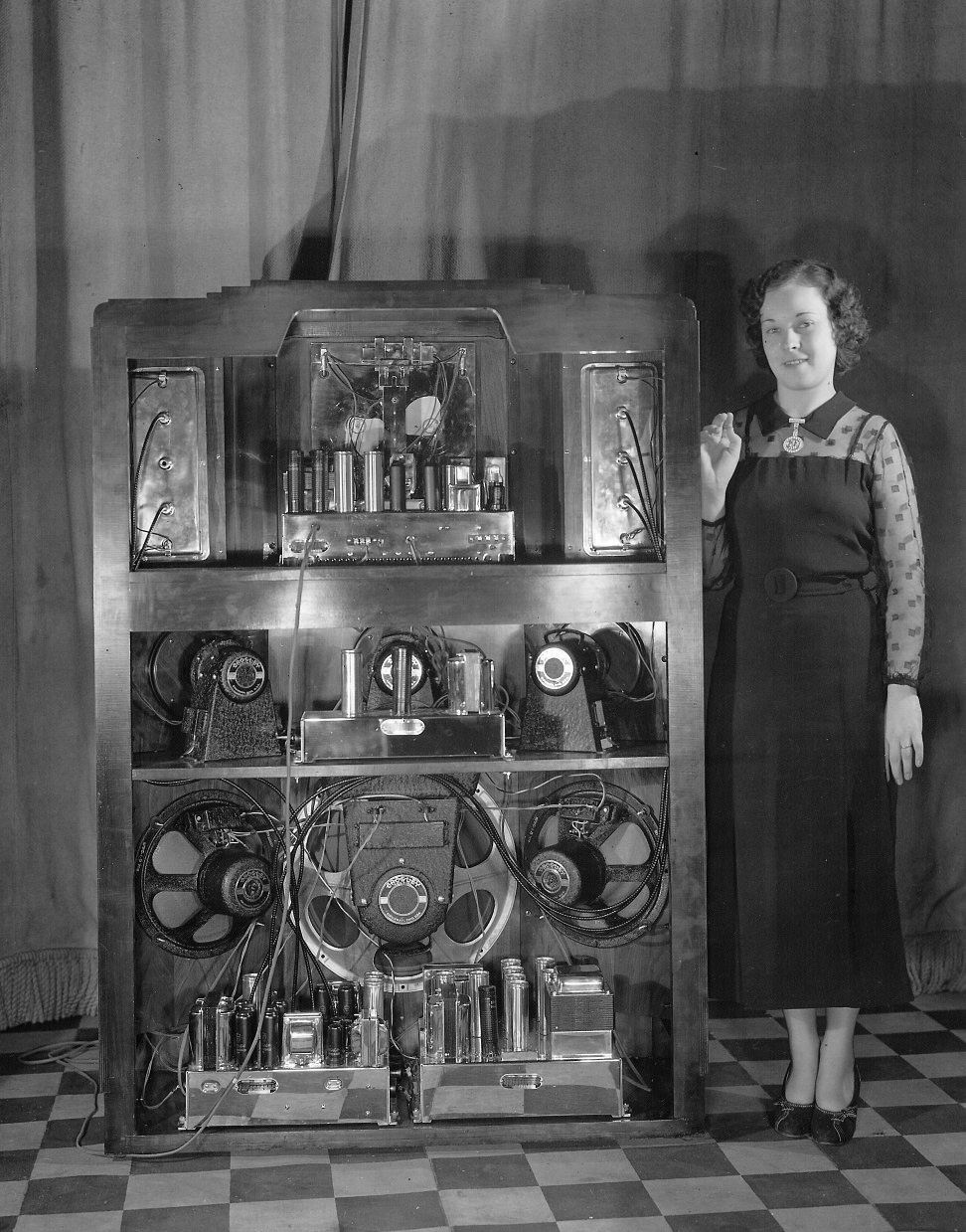
The rear of the Crosley Super-Power set. Everything that could be was chromium-plated.
The set would be called the “WLW Model Super-Power Radio Receiver.” This name was chosen by Powel Crosley, Jr. because it was, as a spokesman later said, “symbolical of the great 500,000 watt broadcasting station — the most powerful in the world.” (Crosley never missed an opportunity to use one product to promote another.)
Early in the spring of 1936, Crosley assigned the task of designing the radio to one of his engineers, Amyle P. Richards. The 31-year-old engineer had his doubts about the project at first. “The logic of the situation was not at once apparent when Mr. Crosley gave the orders for construction,” Richards was quoted as saying. “From the cost angle — engineers cannot ignore costs — it was perhaps the best plan, but from the angle of sheer engineering skill, it was not a desirable plan, but it also must be understood that the plan here adopted was necessarily in accordance with the wishes of Mr. Crosley.”
Although his engineer’s mind questioned the project, Richards enjoyed the challenges that the project presented. In fact, he later wrote that he, “enjoyed every minute spent on the creation of this receiver and welcomed the responsibility of making it a commercial possibility.”
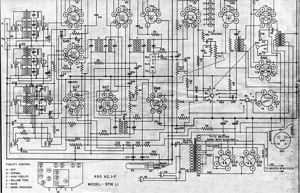
The project involved four basic segments: a variable radio frequency or pre-selecting amplifier, an intermediate frequency amplifier, a pre-audio amplifier, and the power supply. Richards designed a separate chassis for each segment. Three audio channels handled low-, medium-, and high-frequency ranges, assisted by a triple-tuned transformer.
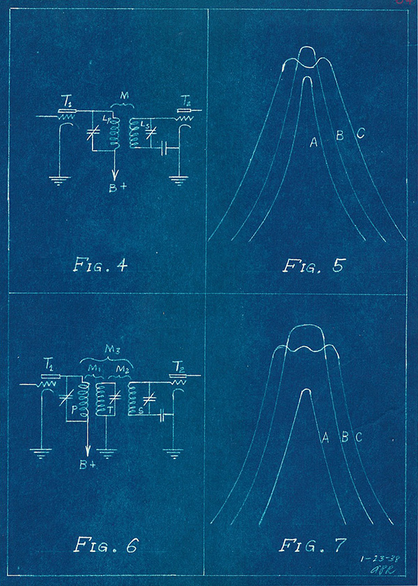
Tuned transformer schematics and coupling.
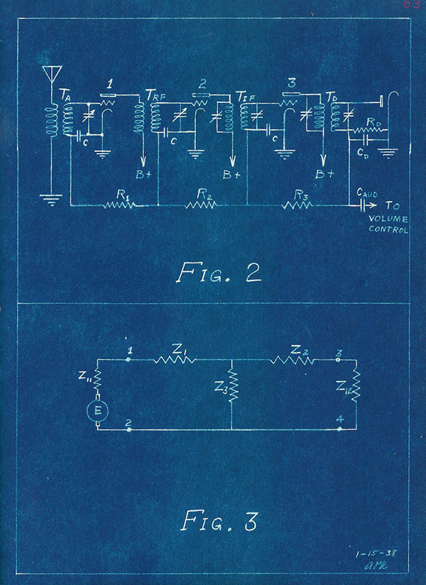
RF tube schematics and impedance network.
Every feature that could be built into a radio was included. Automatic Volume Control (actually gain control — then a relatively new idea) minimized the undesired volume increases that would occur when a station’s signal power suddenly increased or when a listener tuned from a distant station to a more powerful, local station. Automatic Frequency Control prevented drifts from the tuned frequency. By increasing or decreasing the volume to match variations in signal modulation strength, an Automatic Volume Expansion feature compensated for the natural or intentional variations in the volume of the music or other programming that was being broadcast.
In its completed form, the WLW Model Super-Power Radio Receiver indeed surpassed the Zenith Stratosphere model. It had 37 tubes, six speakers, and 75 watts of power. The cabinet stood 58 inches tall, 42 inches wide, and 22 inches deep. Everything inside the cabinet that could be was chromium-plated. The transformer coils, tubes, and speaker frames were finished in black and each chassis had its own serial number plate.
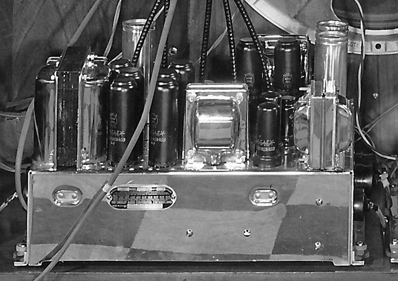
Close-up view of one of the four electronics chassis inside the WLW model receiver.
The speaker bank consisted of three high-range tweeters and two 12 inch “mezzo” or mid-range speakers, plus an 18 inch “auditorium” speaker for the low-range, with the voice coil circuits phased for maximum quality sound reproduction. The speakers were focused in three different directions and the low-range speaker sat in a special cushioned mounting to prevent cabinet resonance. Because of weight considerations, the WLW model was shipped with the speakers uninstalled. (The 18 inch speaker alone weighed 85 pounds.) With the speakers installed, the WLW Model Super-Power Receiver tipped the scales at 475 pounds.
In keeping with the Crosley tradition of adding something extra to everything the company built, the WLW Model radio receiver featured a public address system and a microphone. The microphone was a 4 inch crystal type, attached to the set by a 25 foot cord. The microphone’s input could be switched to any or all of the set’s three audio channels. A two-way switch either cut out the radio entirely or allowed the microphone’s input to be blended with a radio program. This was probably the first account of a radio being equipped with a PA system. The designer rated it as having sufficient volume to address a crowd of 10,000.
The receiver could reproduce the entire range of audible sound — from 20 to 20,000 cycles per second. Its tuner brought in every frequency from 540 to 18,300 kilocycles, which, at that time, encompassed the commercial broadcast, police, amateur, and ship bands, as well as foreign stations.
Such an impressive radio demanded an impressive cabinet. A modern style was chosen and seven different types of wood went into the cabinet’s construction. A grille cloth designed especially for the Crosley WLW model completed the stunning exterior; the fabric’s design was a classic flame motif that was popular in tapestry and furniture upholstery, as well.
Every imaginable user control was included. An eye-catching 12 inch “airplane-style” tuning dial was mounted at chest level and beneath it were two volume controls (one for low and middle frequencies and the other for high frequencies), two tuning knobs, and a special fidelity control that incorporated the ON/OFF switch.
The fidelity control allowed the user to select from five preset frequency ranges. The “Normal” selection passed only the middle range of audio frequencies. A “High Fidelity” selection — ideal for listening to music — increased the response for 40- and 4,000-cycle frequencies by several decibels. A “Mellow Tone” setting made whatever radio program was on sound as though it were issuing from the inside of a large barrel. This was accomplished by suppressing the high-frequency response. A “Bass” selection accentuated bass response and cut off high frequencies. The final setting offered by the Fidelity Control — “Noise Reducing” — emphasized the high- and low-frequency response. A mechanical display to the right of the tuning dial’s center indicated which fidelity setting was in use, including OFF.
The fidelity control feature was apparently popular only briefly in the mid-1930s. It probably added too much to a radio receiver’s cost to appear on any models, except for the high-end ones. Also, many radio owners may have found it too complicated to use.
Tuning was accomplished with two knobs — one for fine adjustments. The knobs turned two clock-like sweep hands (one short, one long) on the dial’s face. Appropriately, the outer rim of the dial was marked with the numbers 1 through 12, just like a clock face. The clock numbers and sweep hands comprised a mnemonic device for remembering station settings. A station tuned in with the short hand pointing at 10 and the long hand pointing at 3 on the dial might thus be remembered as “10:15.” The feature was called “Timelog Tuning.”
A mechanical display to the left of the dial’s center showed the name of the band that was tuned in.
Three tone controls were set in their own panel on the left side of the cabinet — one each for bass, mezzo, and treble control. The microphone input and controls were on the right side of the cabinet. Hinged, curving wood panels covered both sets of controls.
An external feature of special interest was a visual tuning indicator, which was Crosley’s answer to RCA’s “Magic Eye” indicator. This indicator was incorporated into the Crosley trademark at the top of the tuning dial. The trademark consisted of the name “Crosley” with a bolt of lightning passing through it. The lightning part of the logo was cut out and a neon tube was installed behind it. The intensity of this tube’s glow increased or decreased as the voltage in a DC amplifier varied. The effect produced, when a station was tuned in, was a lit, orange-red flash of lightning through the Crosley trademark. The stronger the signal that was being received, the brighter the flash of lightning would be. So, tuning into WLW would make the most of this feature!
The WLW Model Super-Power Radio Receiver was announced on November 25, 1936. The press release for the set was headed, “Here is the Colossus of Radio,” and offered a breathless listing of the components and capabilities of this new wonder of the radio world. The receiver was presented as both powerful and practical. “In spite of the fact that it has a tremendous volume range with a maximum output of 75 watts,” the release explained, “this gigantic receiver can be toned down to arm chair or living room levels and still retain all the original expression of the music as rendered in the studios.”
The set made for excellent PR and Powel Crosley, Jr. surely had a laugh over it with his friend, Eugene MacDonald at Zenith.
The set was priced at $1,500.00. There is no record of how many of the WLW Model Super-Power Radio Receivers were built, but the first sale was made to Wheless Gambill — a Crosley distributor in Nashville, TN. Powel Crosley, Jr. certainly put one in his home and probably sent one to Eugene MacDonald at Zenith.
Designer Amyle Richards received a bonus of sorts for his work. He had earned a Bachelor of Science degree in Electrical Engineering from the Oklahoma Agricultural and Mechanical College in 1927. In 1939, he submitted a thesis on the WLW Model receiver to the college’s engineering department; on the basis of the project, he was granted a Professional Degree in Electrical Engineering. NV
Those Mysterious Call Letters
The call letters by which radio stations identify themselves are a never-ending source of puzzlement. A few have a readily discernable reference to ownership (WABC or WNBC) or actually form a word (WARM). Most, however, were arbitrarily assigned, with no meaning intended.
One rule was established early on, in 1914, but that was only so stations could be identified by country. For no reason in particular, it was decided that all US radio station call signs would begin with W or K to distinguish them from, say, Canadian radio stations, which begin with the letter C. In 1923, it was further determined that stations west of the Mississippi would begin with K and those east of the mighty river would begin with W. A few stations with out of place call signs, like Philadelphia’s KDKA, were left as they were.
Some call signs were granted by request. For example, WKRC in Cincinnati, OH was originally owned by Kodel Radio Corporation. WSM, in Nashville, TN was originally owned by a life insurance company and WSM was requested as an anagrammatic fit for “We Shield Millions.”
WLW, however, is one of the arbitrary call signs. The applicant was Powel Crosley, Jr., on behalf of the Crosley Manufacturing Corporation. The letters WLW fit neither of these. Had Crosley thought to request a specific call sign, the station might have been WPCJ or perhaps WCMC. He might even have requested WCIN (for CINcinnati), but he didn’t and so he was handed WLW.
Of course, there have been attempts to assign meaning to the letters WLW over the years. “Whatta Lotta Watts” was fitting in the 1920-30s, as the station went first to 50,000 and then to 500,000 watts. Any number of WLW employees in the old days (and perhaps now) might tell you that WLW stands for “World’s Lowest Wages.” Other possibilities are: “We Love Watts” and “World’s Largest Wireless.” Still, the fact remains that WLW is an arbitrarily assigned call sign.