Instant IoT Embedded Engineering with No Coding
Embedded engineering is about burying a microcontroller inside a product to turn an everyday object into a smart object. When the smart object is also connected to the cloud, it’s instantly an Internet of Things (IoT) device.
Quantum Integration (https://quantumIntegrate.com) recently introduced a product family designed to create IoT hardware applications by wiring up a few sensors and actuators, dragging a few boxes on a web browser screen, and then with a few mouse clicks, instant IoT.
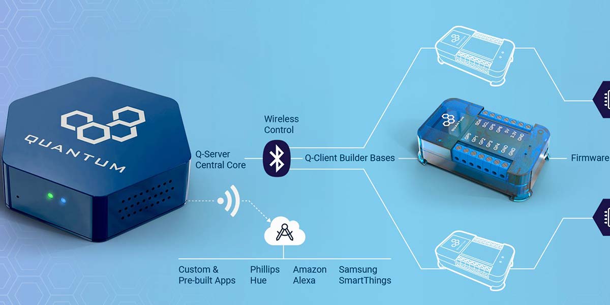
Figure 1 is an example of the hardware system of server, builder bases, sensors, and actuators, connecting the real world to the cloud.
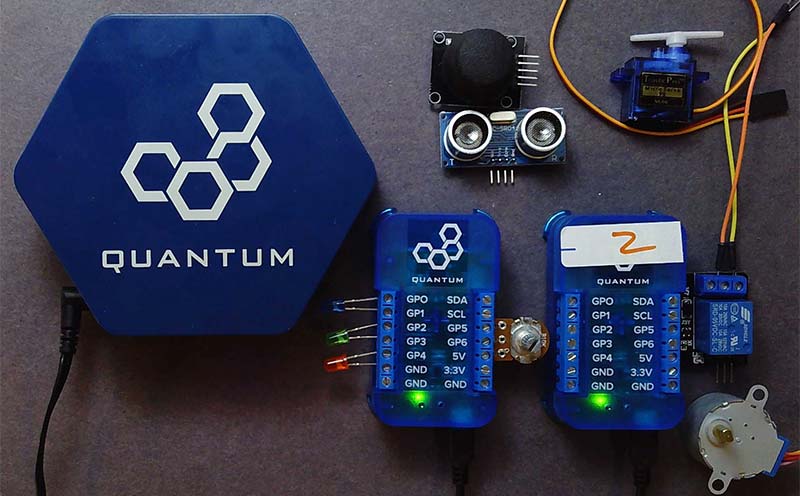
FIGURE 1. An example of the Quantum Integration ecosystem with server, clients, sensors, and actuators.
I had a chance to play with the first release of their starter kit. Once I got over the initial learning curve, I was able to build two simple IoT prototypes to demonstrate cloud connectivity in about five minutes. Here is my experience.
Building an IoT System
Arduinos are great platforms from which to build embedded systems. They can turn a cat toy into a smart cat toy. Connect a sensor and actuator, and you can create a smart light switch that turns off and on when you clap. Attach some wheels and motors with a wireless interface and you have an RC car.
It used to be you had to use a shield like an ESP8266 to connect an Arduino to the Internet. Now, you can purchase Arduino boards compatible with the Arduino IDE (integrated development environment) which have integrated Bluetooth or Wi-Fi on the board.
However, they all have the same limitation. The RF connectivity to the Internet is easy. Writing the software to have the Arduino interact with the Internet the way you want is the hard part. If you’re not a code jockey and you don’t understand AT+CWMODE=3 or JSON or MQTT or PubSubCLient.h, or broker TCP/IP addresses and ports, you will absolutely run into a problem that will stop you in your tracks. If you copy a code snippet and are successful getting it to run, trying to modify it for your specific application can be frustrating.
Whole books are available to help you become an expert, but you often have to go through a good part of the book to learn enough to create your own application. There is a disconnect between the simplicity of the Arduino hardware and the complexity of the software to implement an IoT application. This is the gap Quantum Integration fills.
Their first prototype systems were working in 2017. A Kickstarter program started in mid-2020. The early pre-production units were recently released. I had a chance to play with one of the first production released starter kits.
This is not an extension of the Arduino ecosystem that runs in an Arduino IDE. This is a completely different and independent ecosystem of hardware and software that was built to natively create IoT systems with minimal coding.
As a new system, you must sometimes “unlearn what you have learned” and not try to think of the Quantum Integration ecosystem as a modified Arduino ecosystem. You have to learn the new architecture and plan your project using these new elements to take full advantage of their infrastructure for instant IoT with no coding.
The Learning Curve
I’m sorry to say I have become impatient with reading manuals. While there are extensive help files online, I didn’t find much of what I glanced at terribly useful to get started. All I did was watch a few of the well-done video tutorials on YouTube (https://www.youtube.com/channel/UCrACY-WFU7uIaAzyqo9sScw) and then began experimenting.
The hardest part of using the Quantum ecosystem was learning their jargon. Here is my cheat sheet to what their terms refer:
Q-server: The hexagonal box that connects to your Internet, their cloud, and through Bluetooth to each builder base.
The builder base: The individual boxes (droid bodies) to which you connect sensors (eyes and ears) and actuators (arms and legs) to build a part of your system.
Hardware: Any example of a physical sensor or actuator you connect to a builder base.
Client: The combination of builder base with at least one piece of hardware attached.
Hardware type: The kind of generic hardware — such as an LED or a button or a motor — a collection of which comes natively installed and which you cannot modify. Each hardware type has a specific set of predefined properties and features.
Hardware name: The unique ID identifier you give to a specific piece of hardware you add to a builder base to refer to that specific piece of hardware.
Hardware object: When building the app, this is the virtual representation of the specific piece of hardware that was added to a builder base. This object has all the built-in properties of its type of hardware. Each specific object will be associated with a specific piece of hardware when the app is started.
Hardware object name: Every object in an app has a specific name. The name of the specific virtual hardware object is independent of the name of the specific piece of physical hardware attached to the builder base.
Driver: The specific setup you select and create in the cloud interface using a pull-down menu that tells each specific builder base how to talk to the specific piece of hardware it has connected to it.
Firmware: The collection of drivers that will run on each specific builder base that (once uploaded to the builder base) will control all the hardware pieces connected to it. One builder base has one set of firmware running on it. This firmware will contain all the drivers for all the specific pieces of hardware connected to that builder base.
App: The block diagram you build in their web interface which connects individual, specific hardware objects and how the information and actions flow from one object to the other.
Services: Specific functions each piece of hardware can perform or external cloud interfaces which can be connected. Most hardware only has one service or function it performs. Some can do multiple functions like outputting the X and Y positions in a joystick.
Interface: The set of objects that control how the web interface interacts with the local hardware in an app.
Once I learned the vocabulary, the creation flow of the driver, the firmware and the app, building a few apps was straightforward. I had a selection of sensors that came with the starter kit from which to choose, such as:
- Pushbuttons
- Resistor Pot
- Rotatory Encoder
- X-Y Joystick
- 12-button Keypad
- Ultrasonic Position Sensor
And a number of actuators:
- Two DC Motors
- A Stepper Motor
- A Servo Motor
- Assorted LEDs
- A Relay
- An IR Transmitter
To build the drivers, the firmware and the app require a little perspective on how the system is put together and plays together.
How it Works
The most important innovation in the Quantum Integration ecosystem is the architecture of a complete system with the built-in communication protocol from the sensors and actuators that interact with the real world to the cloud, effortlessly and automatically. The complete system is shown in Figure 2.
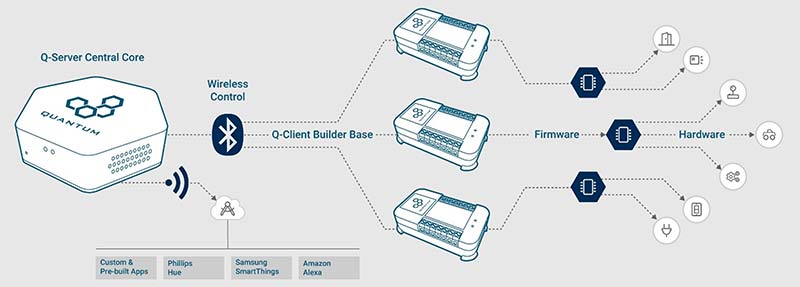
FIGURE 2. The overall architecture of the Quantum Integration system, courtesy of Quantum Integration.
The Q-server communicates to the cloud through your local Internet network. It communicates to the local client builder bases through Bluetooth. All the communication is completely under the hood and transparent to the user.
As a user, all I have to concentrate on is the electrical interface between the sensors and actuators and the builder bases, and the applications that turn these sensors and actuators into robots and cat toys and things that go bump in the night.
The entire interface of selecting drivers, writing firmware, and creating the apps is all done through the Quantum Cloud web browser. This means you are always using the latest software and have access to all the latest drivers and objects every time you open the web interface. Nothing is installed or runs on your computer. Any device with a web browser can be used to create IoT applications.
Once an app is created, it lives and runs on the local Q-server and does not require an interconnect connection.
Each builder base has seven GPIO pins, power pins, and dedicated I2C pins. Any GPIO pin can be a 3.3V digital input or output, a 12-bit analog input, or an eight-bit PWM pseudo analog output. Inside the builder base is a microcontroller, but it’s not an Arduino. Instead, there’s a simple menu driven interface to select or modify a driver for each sensor or actuator. A builder base is shown in Figure 3.
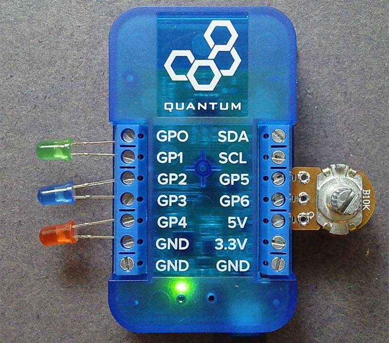
FIGURE 3. A builder base with seven GPIO pins and dedicated I2C pins.
Drivers are the instructions to the microcontroller that tell it how the electrical signals on the input and output pins communicate with the hardware: the sensors and actuators. In the Arduino, you write drivers with digitalWrite and digitalRead or analogRead commands to control digital pins or use libraries that do a lot of under-the-hood routines.
In the Quantum Universe, drivers that tell the builder base how to interact with common types of sensors or actuators are already written. We select the driver for the type of sensor or actuator from a pull-down menu or modify it slightly. These are selected in the web browser interface. The collection of drivers for all the specific sensors or actuators connected to a specific builder base is called the firmware.
Once the firmware is completed, it’s u ploaded with one mouse click to the builder base. The Q-server sends the firmware to the builder base over Bluetooth and the builder base installs it. This is sometimes referred to as over the air (OTA) programming. All of this happens under the hood with one mouse click. This is part of the beauty of the Quantum ecosystem. The connectivity comes natively built in to all the elements. You never see it; you just use it.
The last step is creating the app that tells each builder base what to do with each specific sensor or actuator. The connectivity between different builder bases and the cloud is transparent when you build the app. Once built by selecting specific objects represented as icons for each piece of hardware and connecting the flow of how inputs (sensors) affect outputs (actuators), the app is saved on the cloud and the Q-server.
There is a one-to-one correspondence between the specific hardware objects in the app with the specific physical hardware connected to each builder base. The first time the app is run, you define which piece of hardware on which builder base each object in the app represents. Then, the app runs on the Q-server, commanding each builder base to do whatever it’s supposed to do and communicating to anything on the cloud that is included. All of this is done with menu selections and no coding.
Hello World
The very first project you should do with any new system is a version of Hello World. This was first suggested by Brian Kernigham while he was at Bell Labs in 1974. When you run your version of Hello World, it ties you into this rich history of computing.
With a computer, Hello World means printing the words to a printer or terminal. With an Arduino, Hello World is usually blinking an LED. With the Quantum Integration system, Hello World is demonstrating wireless connectivity between a remote switch and an LED.
Hello World should always be as simple a system as possible. Its purpose is not to demonstrate all the things that can be done, but just to demonstrate that everything is talking and listening to all the elements that need to be. Most importantly, Hello World should have the fewest potential barriers to immediate success as practical.
I’m a minimalist. If I can construct a circuit by direct connection to the electronic interface and not have to go through a solderless breadboard, I can complete it faster and there is less chance of wiring mistakes.
In my first application, I wanted to demonstrate the ability to talk between two different builder bases transparently. All I really wanted to do was use one builder base to turn on an LED when I flipped a switch on another builder base somewhere else in my house.
For the hardware on one builder base, I literally connected the LED between pin GP4 and ground. But wait, what limits the current? Won’t I get like 10A of current through the LED when pin GP4 turns on?
On the output of every digital pin is some resistance that limits the current. Depending on the microcontroller, this is on the order of 50 ohms for an ATmega 328 and 100 to 200 ohms for a SAMD21 microcontroller. When I connect an LED directly between a digital pin and ground, the current coming out of the digital pin will be about 5-30 mA — not a problem for the LED or the digital pin — and making my life easier. I showed some examples of these direct connections in my article in Issue-1 2020 of Nuts & Volts.
As a switch, instead of wiring up a pushbutton and a pull-up resistor, all I had to do was touch a wire between a digital input pin and the 3.3V connection on the builder base. The pin going high on an otherwise pulled LOW pin is the indication that I touched the pin.
This is sort of a modified blink. All I needed to do was connect the LED directly into a digital pin of one builder base and a jumper wire on one digital pin on the other builder base. With the right drivers, firmware, and app, when I touch the wire to 3.3V on builder base 2, the LED on builder base 1 should light up. This configuration is shown in Figure 4.
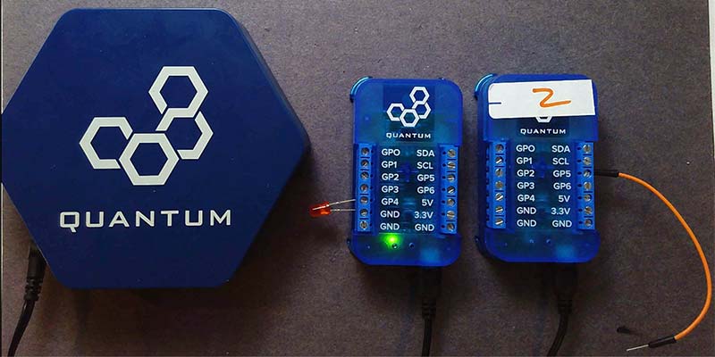
FIGURE 4. My version of Hello World. An LED is directly connected to one builder base and the wire is the switch on the other. The cables to the Q-server and each builder base just supply the 5V power.
This is the extent of the hardware. The red LED is the actuator and the orange wire which I will touch to the 3.3V pin of the builder base as the sensor.
To distinguish the two builder bases, when I set up the Q-server and found the two builder bases connected, I named them droid1 and droid2. In a way, they are mini robots. The builder base is like the body. The actuators I add are like arms and legs that let them perform actions. The sensors I add are like the eyes and ears of the little droids. When the Q-server is turned on, it connects to the Internet and its indicator light flashes two rapid orange lights. This says, “I’m connected to the Quantum Cloud but you aren’t.” After I signed into the Quantum Cloud website, I saw my Q-server online. For security, I entered my six-digit pin to unlock access to my Q-server sitting next to me.
The first step in creating a new application is to wire up the hardware to each builder base. The second step is to create the firmware. The third step is to build the app using hardware objects. The last step is to associate each specific object in the app with each piece of hardware and run the app.
Since I have two different builder bases, each base will have its own firmware uploaded to it. I labeled the firmware on droid1 droid1FW and droid2FW for the other.
Droid1 has my LED hardware. Building the driver for the LED is literally as easy as selecting the type of hardware from a list and filling in the blanks. Since there’s just one specific piece of hardware connected to droid1 and hence one driver to select, this is the extent of the firmware to upload to droid1. One mouse click and the firmware was up loaded to droid1.
The driver setup for the LED is shown in Figure 5.

FIGURE 5. The web interface to select the driver for the LED that will run on droid1 is built from a menu selection.
The type of hardware I selected is the predetermined LED option. I named my specific LED connected to droid1 redLED.
Once I completed the drivers for droid1, I uploaded the firmware to droid1 by clicking the upload button and selecting droid1 from the list of builder bases.
On droid2, I added the switch. There’s no switch option as a type of hardware from which to select. However, there’s a button type of hardware. This does the same thing, so I used this hardware type. I named it switch. In the same way, I created the driver and added it to the firmware for droid2 and uploaded it to droid2.
My hardware was complete, so it was time to build the app. All I wanted to do was have the trigger signal from the switch when it was pulled high (when I touched the wire to 3.3V) trigger the red LED and turn on.
Building the app is literally as easy as selecting the various types of hardware objects from the selection of built-in options. Each object in the app corresponds to a specific piece of physical hardware and its driver connected to any of the builder bases.
With connectivity built into the product architecture, it doesn’t matter to the app on which builder base any specific piece of hardware is connected to.
For my Hello World, I selected an LED object and a button object. The names of these objects can be anything I want. They’re not associated with the specific pieces of hardware tied to the client builder bases until I start the app. This is when I assign each object with a specific piece of hardware. The complete app in the app builder is shown in Figure 6.
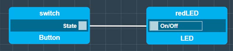
FIGURE 6. The complete app consists of two objects. The type of object is the bottom label. The name of the specific object in the app is the top label.
To make the association between the hardware I added to the builder base and the objects I connected together in the app, it’s important when I add hardware to my droid and build their drivers to use the same type of hardware in both the app and the driver.
When I started the app and associated the objects in the app with the physical LED and button, sure enough, I touched the wire to the 3.3V pin on droid2 and the red LED on droid1 turned on, even from across the room. Hello World!
Instant Remote iPhone Controller
The real power of the Quantum Integration system is the ability to connect my local hardware to the cloud and my PC, tablet, and smartphone connected to the cloud and part of my IoT project.
Included in the starter kit is a simple SDR relay capable of switching a device that can switch a 120V voltage and up to 10A current. While this is capable of controlling many simple appliances powered by AC house current, I do not recommend anyone connect the AC line power into this relay unless you are an experienced “power” user.
Instead, I connected just a simple ultrabright LED through a 100 ohm resistor to a 9V battery to emulate a remote device. This relay comes connected on a small PCB (printed circuit board). The three input pins are for a gnd, 5V, and a control signal. The control signal triggers the relay when it goes high.
There are three output pins on the relay’s circuit board. The center pin is the common pin. The left pin (looking at the pins head on) is the normally open (NO) pin connection, and the right pin is the normally closed (NC) position. I connected an LED through a series resistor and into a 9V battery in series with the common and NO pin. With the relay off, the LED was off.
There is no relay driver in the collection of drivers, so I used a simple digital pin driver, set for normally LOW. After I uploaded this firmware, I created an app.
There’s a collection of objects available that correspond to web interfaces under the Interface objects. I wanted one that was a simple switch: click it on, click it off. This is the Switch object. With this object included in the app, it automatically places a switch icon on my Quantum Cloud dashboard which will control the hardware. The entire app is just the two objects shown in Figure 7.
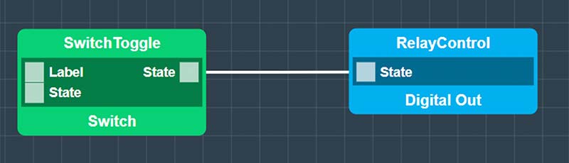
FIGURE 7. The complete app to control a relay from any web browser. The green object Switch type is an interface object that places a switch control on the dashboard of my Quantum Cloud.
When the app runs, I opened up my dashboard on my Quantum Cloud account, accessed the app, and saw my switch on the dashboard. This is shown in Figure 8.
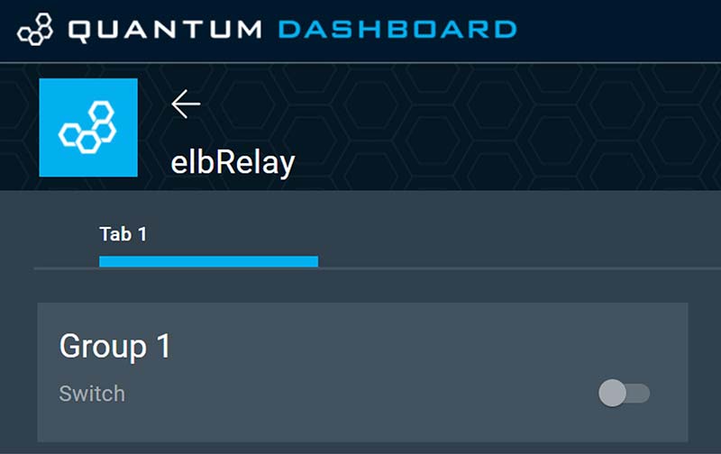
FIGURE 8. The dashboard on my PC has one button. When I toggle it, the relay closes and the LED turns on.
The key feature is that this web interface can be accessed from any browser on any device. I opened up the Quantum Cloud on my iPhone and was able to trigger the relay and turn the LED on from anywhere. Figure 9 shows the complete hardware system with the web interface on my iPhone.
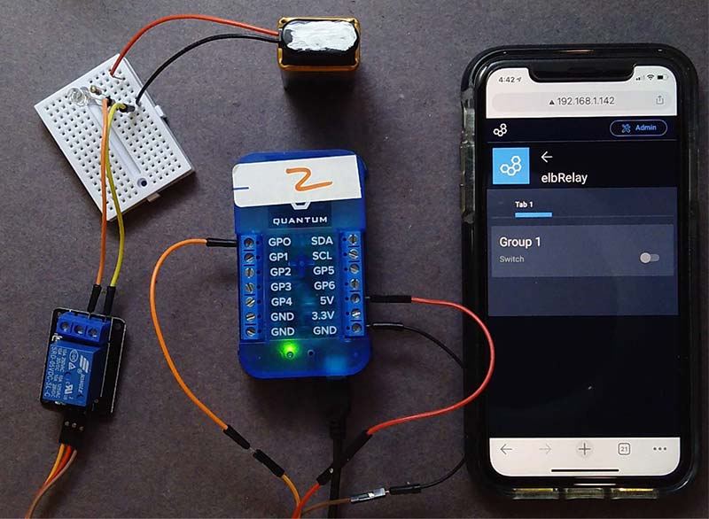
FIGURE 9. The complete hardware system with my iPhone running the cloud-based interface.
What’s Next
Once I got over the initial learning curve to understand the architecture of a Quantum Integration IoT device and the process of connecting hardware devices, creating drivers, uploading firmware, and writing apps, it was trivial to create an app that seamlessly integrated with the web.
In literally five minutes, I was able to create a hardware system that wirelessly interacted between sensors and actuators located anywhere within my house. In less time than that, I created a cloud-based interface that turned a relay off and on.
The price we pay for this easily customized system is the requirement to only include sensors and actuators for which there are pre-installed drivers and app objects. The Quantum Integration ecosystem comes initially with a limited number of sensors and actuators. Over time, more elements will be added to the ecosystem.
In the meantime, as their advertising suggests, this integrated collection of hardware, drivers, firmware, objects, and app features with seamless wireless and cloud integration, offers a sandbox in which to quickly create IoT prototypes.
The two simple examples I quickly implemented just scratched the surface of what might be possible using other hardware sensors and actuators. NV