This is the second part of a three-part account of an extraordinary 10 year engineering project I undertook that succeeded against all odds. My last article explained the planning stages, fabricating of the hull and rudders, the propeller, and the silicon mold preparation for my five foot submarine project.
This time, I’ll explain and show the actual assembly of the components into the overall body of the sub itself. As I mentioned in Part 1, no matter what type of DIY work you are engaged in, you will find herein some electro-mechanical assembly techniques that will prove helpful.
Hull Preparation
The hull is ready to have the openings on the top and bottom cut out. Figures 1 and 2, respectively, show the flood holes on the bottom and upper hull which were cut out.
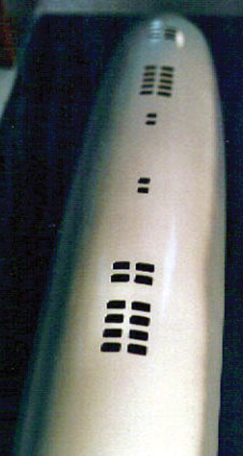
FIGURE 1.
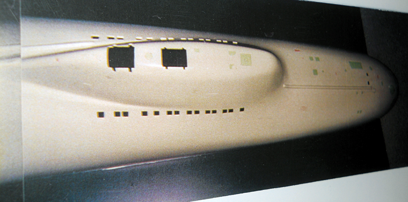
FIGURE 2.
Sidebar Figure A shows the small electric saber saw I used for the holes. This is a 12 volt saw, so I needed to connect it to a 12 volt battery. The saw has two small blades that reciprocate past each other, making a nice cut through the fiber-glass epoxy hull and making the hole cutting easy. Figure 3 shows the method I used to connect the hatches to the upper hull.
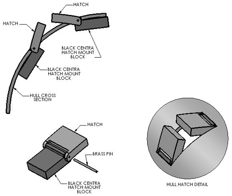
FIGURE 3.
This simple three-part system worked well and needed the usual fine sanding and fitting. One small .052’’ diameter brass rod holds the hatch to the centra (plastic) block, which then attaches to the hull with super glue. You can speed up the drying time of super glue by sprinkling baking soda on it. Figure 4 shows the finished hatches on the model.
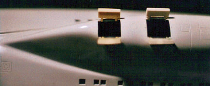
FIGURE 4.
Stern Assembly
The propeller components in Figure 5 are the shaft, the stuffing tube, the propeller, and centering block.
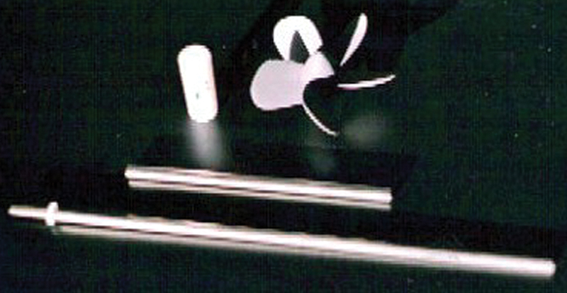
FIGURE 5.
The propeller shaft stuffing tube will be press-fit into the centering block which will be positioned as shown in the rudder detail in Figure 12. The stainless steel stuffing tube is hollow and allows the propeller to pass through it, while the stuffing tube holds the propeller shaft in position. I affixed the propeller to the propeller shaft with 222 Loctite to make sure the propeller won’t fall off while in operation. I have lost propellers — fortunately — while close to shore. Also, before the final stern assembly is completed one needs to examine the unique problem this submarine has with its rudder-propeller configuration.
Rudder Yokes
The four rudders on this submarine have to operate in pairs; the top and bottom ones operate together as one, while the two horizontal rudders operate together as the other pair. There has to be a way for one servo operated pushrod to operate two rudders at a time. My solution is the use of the brass rudder yokes in Figures 6 and 7.
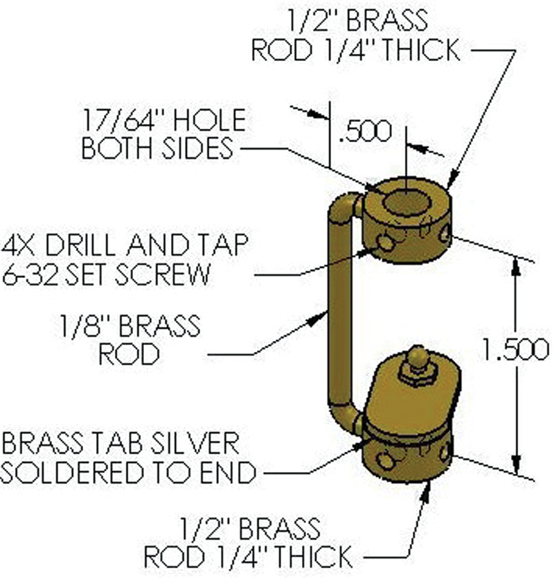
FIGURE 6.
.jpg)
FIGURE 7.
Figure 8 shows the final configuration these yokes assume when mounted in the submarine and how the propeller shaft passes through to the propeller.
.jpg)
FIGURE 8.
The rudder yokes are made up of four parts. There are four 1/2” brass rod pieces cut to 1/4” and drilled at the center for 17/64”. Two pieces of 1/8” brass rod are then cut to 2-1/2” and 2-3/4’’ in length, and taped at each end for 6/32”. They are shaped as depicted in the drawings. Next comes some silver soldering fun.
MAPP Gas
The small brass plates on each yoke assembly need to be silver soldered in place and later have a small ball crank ball positioned on them. Silver soldering is necessary to complete this task. In the soldering realm, you can solder by using increasingly hotter gasses. The lower temperature gas is butane and the hotter gas is propane. For brass and other silver soldering applications, one must use the very effective MAPP gas. MAPP gas kits are available from most hardware retailers.
There are a number of tricks in using MAPP gas. MAPP gas comes with two bottles and a small stand to keep the bottles facing slightly upward. You have to keep the bottles in a slightly upward position or the lit gas will steam out in a pencil thin stream and scare the cat. Also, the MAPP gas has another very sinister design.
The gas bottle and the oxygen bottle turn on and off in different directions. When you think you are turning off the oxygen, you are actually turning it on. This tank empties very quickly. Study the MAPP gas procedure carefully before you begin using it. MAPP gas is a great solution to silver soldering.
Rudders
Figure 9 shows the holes needed to mount the rudder brackets to the hull.
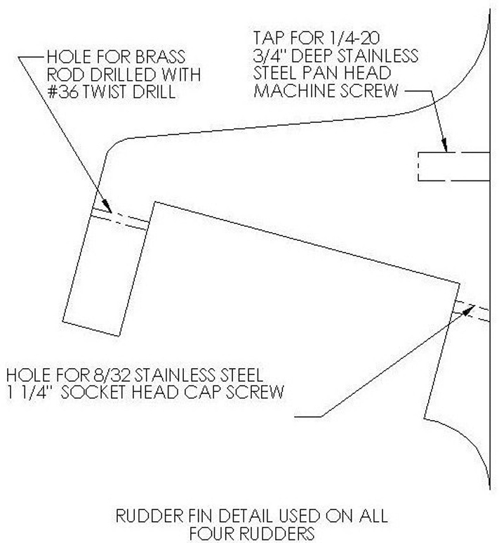
FIGURE 9.
The small holes in the yokes are sized to fit the head of a 1-1/2” x 6/32” stainless steel socket head cap screw. The head cap screw will anchor with a set screw into the rudder yokes and turn the rudders.
Figure 10 shows the two horizontal rudders with the 6/32” socket head screws in position and the rudder yoke in approximate position. When these rudders are mounted, there is movement where the brass rod enters the 1/2” attachment point and allows for variability in alignment.
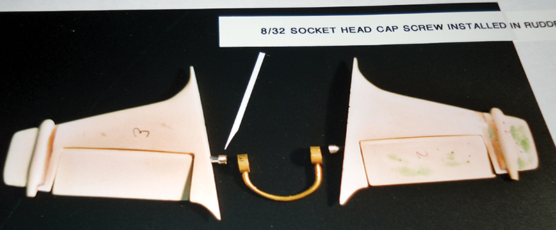
FIGURE 10.
Figure 9 also shows the other mounting screw holes. These 1/4” holes will allow the rudders to be mounted to the hull body and super glued in place.
Figure 11 shows the completed lower horizontal rudders and propeller shaft detail.
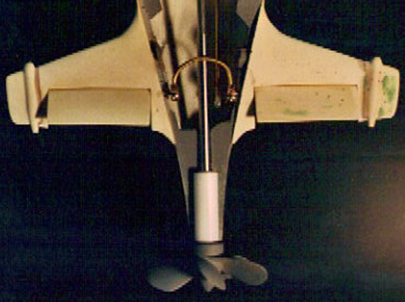
FIGURE 11.
The other rudder yoke will mount in place with the permanent fixing of the top hull section to the bottom hull. Figure 12 shows the completed stern assembly which will remain as a separate permanent assembly from the upper hull.
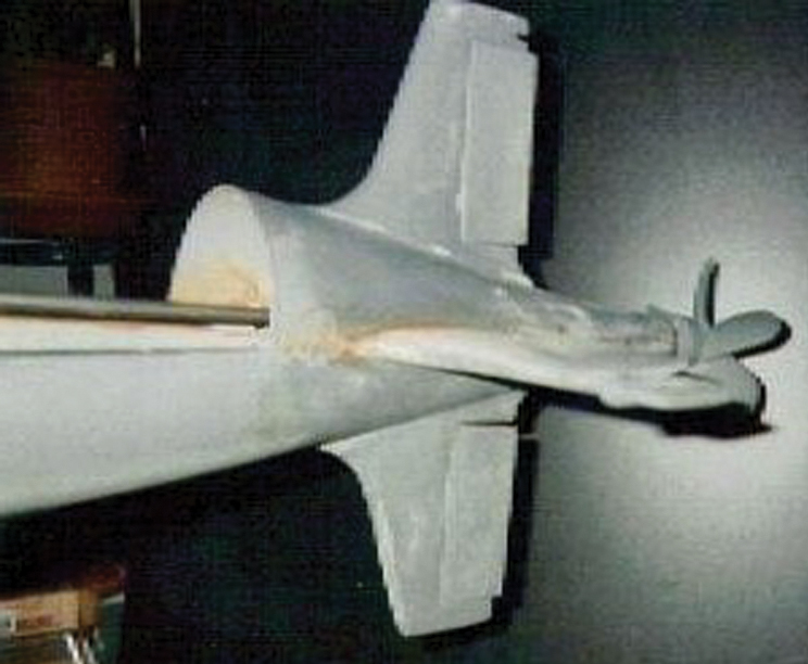
FIGURE 12.
The propeller shaft will remain removable and will be left out, as it will be easier to connect the rudder bell cranks with the shaft out of the way. Later, the propeller shaft will connect to the motor drive shaft by the aid of a flexible coupling. A flexible coupling is a metal or plastic connecting unit which mounts between two shafts. These two shafts don’t exactly match and allow for misalignment where the two shafts meet. See the flexible coupling in sidebar Figure B.
Another challenge looms in the next assembly question which is how to connect the top hull section to the bottom hull. I will explain my ingenious solution to this problem in the following paragraphs.
Watertight Cylinder
Figures 13 and 14 show my stern-mounted watertight cylinder. This part of the build was great fun. One item which gave me a great leap in electrical savvy was the purchase of a 12 volt Pittman motor. The motor is the heart of this cylinder. The cylinder has three simple components: two servos and the motor are housed in this watertight chamber. I cast the end-caps and bought the O rings that seal the cylinder. Mike’s Subworks sells the shaft seals which allow for the servo pushrods to penetrate the end-cap and keep the cylinder watertight.
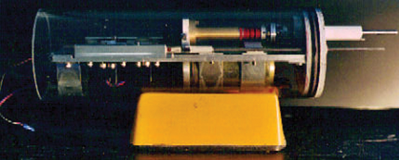
FIGURE 13.
Close observation shows the motor in Figure 13 to be mounted low in the cylinder to help create a low center of gravity for balance. This wasn’t the great idea I had thought it was at that time, because it required me to move the whole cylinder to the front of the boat to allow for the cylinder shaft to match up with the rear shaft as it exited the stern.
Later, I found that I lost space for my electrical box by moving this cylinder forward, since I needed the ballast tank to be in the center of the ship. I wouldn’t make it that way again. Preferably, the motor drive shaft should be centered with the propeller shaft exiting the sub.
I made a prototype mounting plate out of cardboard to locate the openings for the motor and servos. I later made a second prototype out of plastic, then the final one out of aluminum. To make sure that the servo’s sweeping motion wouldn’t wear out the shaft seals, I replaced the servo arms with gears and ran the pushrods with a rack and pinion system in order to push the pushrods straight through the rear end-caps. Figure 14 shows the cylinder top view and the round nylon pinion gears which operate the rack and pushrods. The rack and pinion gears are at the sides and have a small idler gear to keep the racks flat against the channel they are located in.
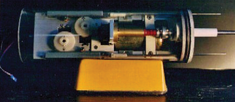
FIGURE 14.
In lowering the motor in the cylinder, I needed to use a short slotted belt and two gears to transfer power to the short propeller shaft. The motor shaft faces the bow and transfers motion rearward through the end-cap via a short propeller shaft over the top of the motor. This again connects with the always useful flexible coupling. I used another version of the flexible coupling to connect the short shaft inside the cylinder seen in Figures 13 and 14 to the short shaft outside the cylinder.
The flexible coupling in the cylinder is the item to the right of the red bearing in Figures 13 and 14. At the extreme rear of the cylinder is the stuffing tube (in gray) containing grease which seals the cylinder from flooding with water. Grease is a good sealant and is what creates a watertight seal at the propeller shaft.
Cylinder Clips
The watertight cylinder is held in the hull using the plastic supports shown in sidebar Figure C. Holding the cylinder in place is a stainless steel bracket (figure 15) made from .030’’ feeler gauge.
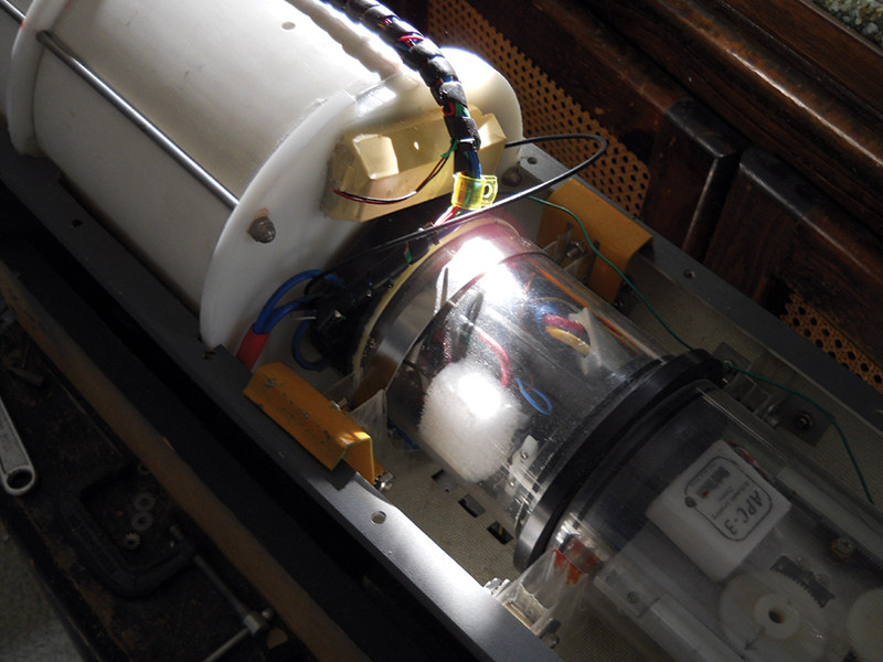
FIGURE 15.
Figure 16 shows the ingenious yellow clips which serve two duties.
The problem of holding down the top hull to the bottom hull was an issue I deliberated about at length. The hull pin alignment system requires that the upper hull must be lifted straight up from the bottom hull. I also had to hold down the watertight cylinder. Somewhere in the recesses of my mind, the solution to this issue dawned on me.
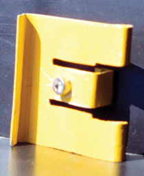
FIGURE 16.
I thought I would use clips (figure 13) at the hull mid-point of the lower hull to hold down the upper hull and use a small hole in the hull side to push the clips open and release the upper hull. The solution was the .030’’ feeler gauge that was to hold down the watertight cylinder. The outward pressure created by this feeler gauge would act as a spring to push the yellow hull clips outward. The outward pressure can be countered by pushing the clips inward with an Allen wrench inserted through the small holes in the hull which would allow the upper hull to lift off the lower hull. I never planned on this as a solution, but I could tell what the potential was when I saw it. Two small holes below the waterline on either side of the hull would be the sites for my opening locations. See sidebar Figure D to view the opening procedure.
The remaining connections are the pushrods at the rear of the watertight cylinder that connect to the rudders. The detail of the connections is shown in Figure 17.
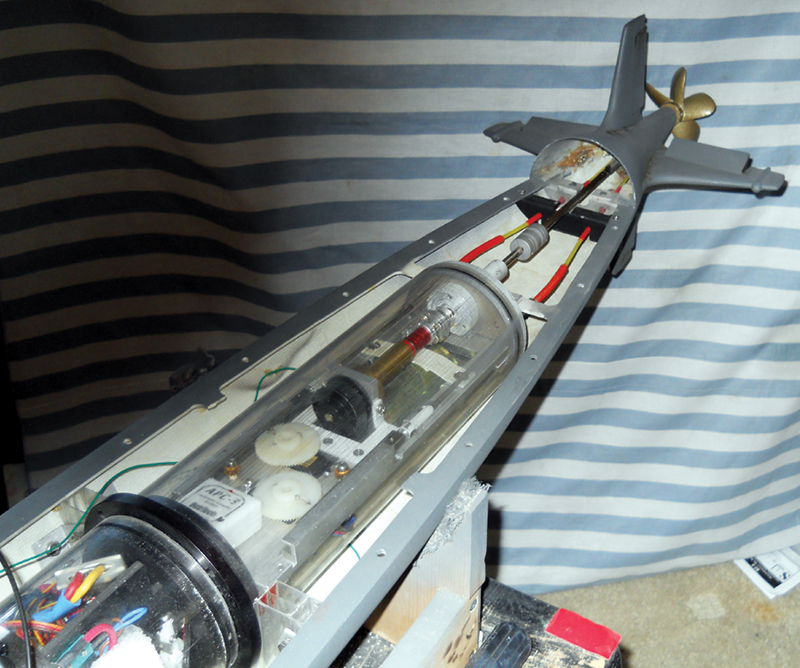
FIGURE 17.
I glued these plastic rods to the pushrods exiting the watertight cylinder. There are many ways to connect the push-rods to the rudder yokes.
The typical connection from the pushrods to the rudder yokes is via brass rods. I liked the plastic red and yellow rods when I saw them in a model plane hobby shop and used them. I like the mixing of materials from one engineering application to another.
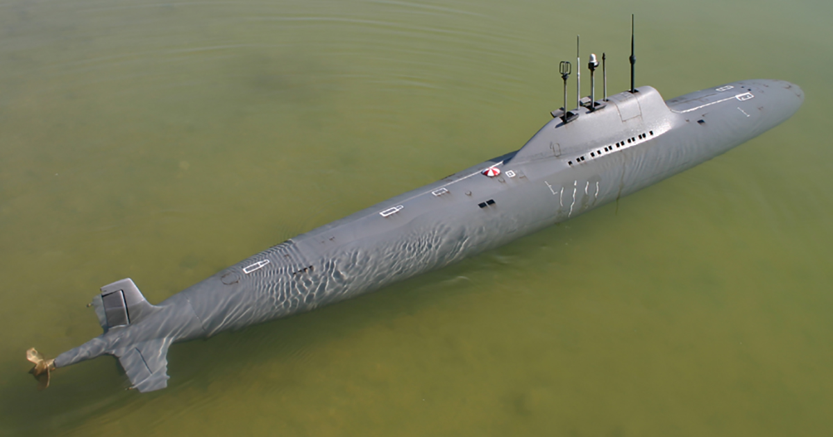
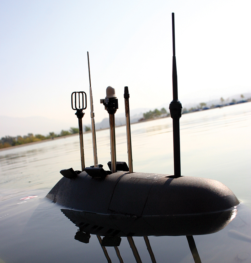
Figure 18 shows the antenna array.
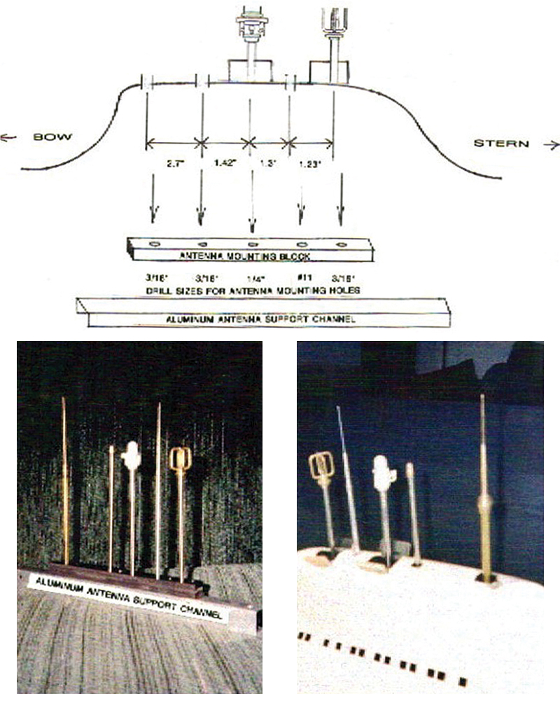
FIGURE 18.
These units were mostly turned on a small lath and soldered together.
Closing Thoughts
In Part 3, I will explain the twists and turns the electrical system put me through. I will also show you a method whereby you can increase the electrical capacity of your radio transmitter by a thousand percent. Further, I will provide the answer to the question on why my speed control would heat up and stop running. How did I stop the pressure reserve tank from losing air pressure? I will also detail the engineering and designing issues of the air compressor system. Just when I thought I had it all figured out ... NV
Tools and Tips (Sidebar)
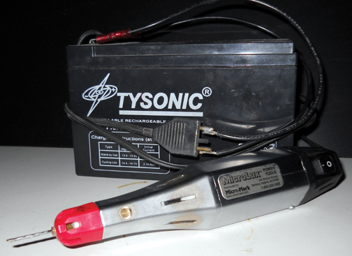
FIGURE A.Twelve volt reciprocating saw and battery used to cut flood holes. (Back)
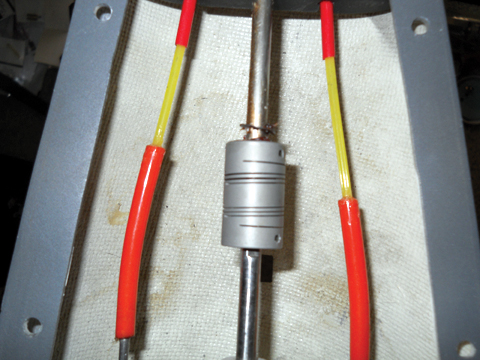
FIGURE B. Flexible coupling used to connect the propeller shaft to the motor drive shaft. (Back)
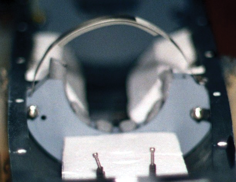
FIGURE C. Watertight cylinder hull supports. (Back)
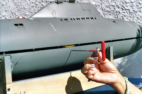
FIGURE D. "T" handle Allen wrench inserted into hull clip release holes which are used to separate the lower hull from the upper hull. (Back)
Special thanks to Carmencita Briones for her outstanding editing work, and to Matt Hall and Pat Green for their help with the graphic images included in this article. Contact the author at [email protected].