A stepper motor should work and there are already stepper motors being used in cars under the hood. You will need:
- An encoder to measure the position of the gas pedal
- A device to convert this position into pulses
- Another device to use the pulses to power a stepper motor
- And of course, the stepper motor itself
Digi-Key sells an encoder with 16 different pulse counts per revolution, set with tiny switches, for 26 bucks, part number AMT103-V. US Digital sells a chip that will convert the encoder output into pulses that a stepper driver can use. Part # LFLS7184, $3.50. Interinar sells a stepper driver board for $36.00. Stepper motors are available surplus everywhere.
You will have to have an idea which stepper you need if you decide to go this route. You will also need a 5 volt power supply for the encoder and the 7184 chip. US Digital also sells encoders but none that have 16 different resolutions, as far as I know. I have used all the devices mentioned, bought from the companies mentioned. I have used them for a similar application, so I know they will work. The encoder mentioned is a robust device that will be better over time than a cheap pot to measure the foot pedal position. Since the encoder has so many different resolutions it should be fairly easy to find a ratio between the foot pedal position and the throttle opening.
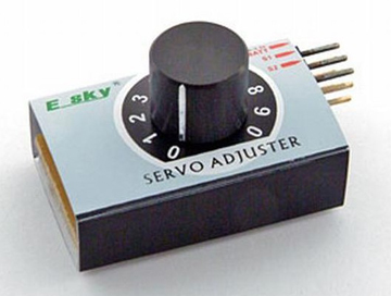
You could also use an RC servo to open the throttle. These servos need a pulse train of a particular width to know how much to move. The pulses must be constant, because when the pulse train stops the servo returns to the starting position. So, you need some kind of servo controller that will use a pot connected to the foot pedal to tell it how wide to make the pulse it sends to the servo.
The stepper solution suggested above, pretty much just requires connecting the different parts with wires according to the info in the data sheets. But, you can make your own servo controller from a 555 timer, some fixed resistors, some variable resistors (AKA pots), and some capacitors. You will need to solder all this together in an enclosure. This link: pcbheaven.com/wikipages/How_RC_Servos_Works/ will explain how RC servos work and has a sample circuit that you can build to control the RC servo.
One advantage of the RC servo is that it is an absolute positioning system. A certain resistance measured at the foot pedal results in a certain throttle position. The stepper system described above does NOT work that way. The throttle must be at the zero position when power is removed. If the throttle is at half way when power is removed, then the pedal will start to move the throttle from the half way position when power is restored, unless some type of mechanism always returns the throttle to the fully closed position, when power is removed.